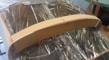
I started off today by clearing off the big, convoluted pile ‘o stuff off the floxed/micro’d in forward avionics bay cover reinforcement piece. I was quite pleased with how it came out.
A couple of reminders on this thing. First, this piece is the first of 4 pieces to get installed. Just think cardinal headings and you get the gist. Next up will be the aft piece that attaches to the top front edge of the instrument panel.
Next, when all 4 pieces are in place, interconnected, and glassed, this area will provide reinforcement from one fuselage side to the other and replaces the top foam avionics deck/aft nose cover that the plans says to glass in place just forward of the instrument panel.
Lastly, this forward piece specifically also serves to increase the height of F28 about 0.4″ to allow for a better flow of the top nose profile and removes a flat spot that was apparent in the nose contour.
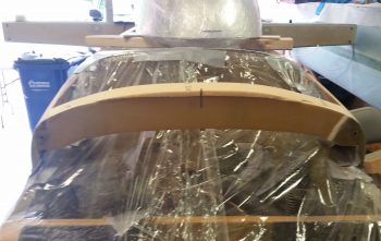
Here’s a view from the aft side of the first of 4 pieces to go in around the perimeter of the avionics bay.
Before I went any further, I took a good half hour to ensure that the right side top forward longeron & F28 were trimmed, sanded and shaped to match the left side. As per my usual response, they’re not perfectly matched, but pretty darn close.
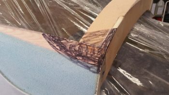
Here I used a Sharpie as a sanding guide coat to “flatten” the top side on the right to better match the left side.
Pardon the bright sun in the background, but here’s a decent depiction of the top nose section “corner” curves now. Much, much better than they were before and I’m very pleased with how they turned out.
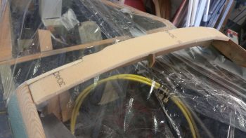
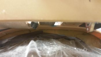
I then cut, shaped and floxed in place the 3/8″ thick x 2.2″ wide PVC foam piece to the front top edge of the instrument panel. Since this too has the apparent requisite pile ‘o crap on top of it to hold it all down in place, I grabbed a shot from underneath. It’s the first foam structure visible just above the gray tape line… and a bit more visible on the right side of the pic.
To get the foam to behave, especially on the outboard edge curves, I drilled a series of small holes along the top edge of the instrument panel and used nails to keep the foam aligned properly.
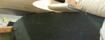
Here’s a view of the right side reinforcement foam piece. As you can see I cut relief lines in the foam, although this piece actually snapped off entirely at the top relief line as I was setting it in place. No worries of course since I just micro’d it in place.
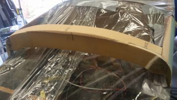
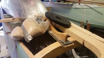
And here’s the aft foam reinforcement piece, or rather the pile ‘o crap securing the aft foam reinforcement piece. This is #2 of 4 pieces with the side pieces coming up next.
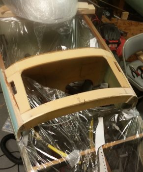
<Fingers snapping> Voila! And here are the side pieces almost completely in place. If you look closely you may be able to see that the front inboard corners are sticking up about a foam’s width high, due to the shape and curvature of the nose. I floxed/micro’d both side pieces in at the aft side and about 2/3rds of the way down the aft outboard edge (to the longeron) and will let them completely cure before making the minor twist at the front edge to secure the side piece to the front cross foam piece’s aft edge.
This is a very good shot showing the access I’ll have to the avionics through this hole created by the 4 foam edge pieces. Yes, this access hole is significantly larger than what many builders have done by creating an access hatch in this area of the nose. I honestly feel (IMO of course) that once the glass is in place that there will no loss of structural integrity in this area, especially when the cover is secured in place.
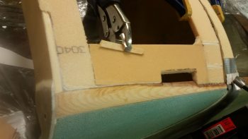
Here you can see –about 5 hours later– I’ve micro’d (foam) and floxed (foam to longeron) the front of the side foam piece to the front cross foam piece’s aft edge using a nail to align and secure the 2 pieces. The clamped on vise grip is to induce a slight twist to get the outboard edge to pivot up a hair (about 0.050″) –using the nail as the fulcrum– to better align the side foam’s outboard edge with the longeron, elevation-wise.
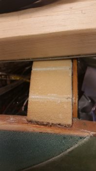
The slot in the side foam piece (on both sides) is for a length of structural hinge that will be attached to the underside of the aft nose/avionics bay cover on a vertical tab and will align and attach to an interlocking length of structural hinge that will be floxed/glassed onto the underside of the longeron. The hinge pin will be modified with basically a set screw on the aft end that will be secured into a threaded point on the instrument panel, one in each upper corner of the panel. When the cover is to be opened, unscrewing the hinge pins and sliding them aft will complete the hinge pin removal step.
[There will be a circlip on the hinge pin assembly that will A) not let the hinge pin be removed (or lost) from the panel without specific effort, and B) not let the hinge pin exit the aft-most tab on the longeron mounted hinge assembly, thus ensuring the hinge pin assembly is always ‘locked & loaded’ alignment-wise and ready for pain free insertion into the aft nose/avionics bay cover’s hinge assembly once the cover is closed and the upper hinge bracket drops into alignment with the lower hinge bracket].
After a LOT of assessing, measuring, research, assessing, cardboard mockups, more research, more measuring, pondering, etc. I finally came very close to the final configuration on the plan for the interface of the nose/avionics bay substructure, the aft nose/avionics bay cover, and the front canopy skirt.
With my researched and tested plan in hand, I got to cutting some foam. First up was the 1/4″ thick PVC foam that will make up the BOTTOM, permanent glare shield substructure. I was originally going to just use a number of plies of glass for the glare shield sub structure, but I needed a bit of depth from the top of the instrument panel to create a drop down edge going aft for the front canopy skirt to seat onto/into.
The 1/4″ thick foam is a compromise for getting some depth/thickness for the glare shield and also the max thickness of any intrusion of the instrument panel’s perimeter in regards to both the physical clearance of panel components and visibility of the panel.
You’ll see later on that the front edge of this 1/4″ glare shield sub structure will get beveled at an angle going forward, and will support the aft nose/avionics bay cover that will follow that beveled edge and create a lip going aft of this foam (and glassed) glare shield sub structure to sit under and “interlock” with the bottom edge of front canopy skirt.
Also, as a point of note, the permanent glare shield substructure will be where the strip of blue LED cockpit lights are permanently attached to… so that the lights are tucked up and out of the way..
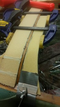
The front-to-aft depth along the majority of the foam glare shield substructure is 1.3″, while the flare at each end is 2.4″ thick. My estimation of total foam width (accounting for the down curve and angle at each end) during foam cutting was about a half inch too long, and since each outboard end was specific in design and the middle area was static in its 1.3″ width, I had to cut about a 1/2″ out of the middle and install the glare shield foam as 2 separate pieces. Since I have no “backside” real estate for nails on this go around, I tried to hand jam it with flox and some 5 min glue dabs along the length. Well, the 5-min glue sorely disappointed and I ended up scrambling to clamp it and weigh the left half 1/4″ foam glare shied substructure piece in place.
It was late so I’ll let the left half cure before tackling the right half tomorrow.
Again, I’ll continue to work the nose substructure for the aft nose/avionics bay cover and the interface with the forward nose structure and aft canopy structure as well. I have to say that in my research on the interface between the substructure, cover and canopy I stumbled across some gems of knowledge that will greatly help in constructing the canopy frame (regarding canopy frame rail width).
Creating a modification such as the aft nose/avionics bay cover is always slow and time consuming, not to mention quite maddening at times, but I really feel that having to take about 5 minutes to deal with hardware removal and then being able to rotate a cover forward to expose and provide access to the avionics bay and F28 forward/canard mounted items such as GPS antennas, airspeed switches’ adjustment screws, etc. . . . all pretty much on the fly and on demand will be quite worth this mod.
Moreover, it will clean up the external flow and look of the nose since I will have only one large hatch and then only one other break in the nose at the forward edge of the cover, just forward of the canard. In addition, it allowed me to do the top canard tab long bolt attachment mod which although clearly not a mandatory mod, is definitely my preference. Finally . . . yes, to be fair, I will add a couple of break lines on each forward fuselage side between the aft edge of the elevator/canard to the instrument panel edges. These breaks (and the increased build time!) are honestly the only downside to incorporating a cover on the nose.

Hi,
This kind oh hystery is inspiring!
Hi,
Definitely some boring reporting at times on the individual tasks to build an airplane, so I’m glad to hear that I’m inspiring other folks out there!
Thanks!