Happy New Years Eve everyone!
I didn’t get a lot accomplished today since it’s New Years Eve. I did spend a good hour+ getting an order in with McMaster-Carr & another with SteinAir. I have another teed up for Aircraft Spruce that I’ll be pulling the trigger on in the next day or so. Being a former military bubba and a project manager, I try to work my logistics first thing in the day to keep the pieces parts flowing in so they’re on hand when I need them and I don’t hit any work stoppages.
Just about every time I venture upstairs I quickly hit the computer to update lists, spreadsheets, diagrams, and online order pages that I have perpetually in the making to ensure my info is as updated as possible. Inventory control especially is a time buster, but a critical part of build project… again, especially a plans build project heavy with a lot of disparate off the shelf & homegrown modifications.
But back to the build . . .
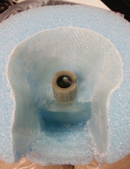
I started off today by hitting the edge of last night’s interior nose cone layup with the Fein saw. I also took my round screwdriver-shaped Perma-Grit tool and knocked down all the glass “gotchas” on the edge of the overlapping glass edges since I didn’t –WAIT FOR IT!– peel ply this layup. I know right?! Always a first for something . . . ha! Actually, there is something very textually and visually appealing about un-peel plied glass.
With the amount of flox I put around the front face of the pitot tube (in relation to the pic above, but actually the bottom edge as it sits on the airplane) and around the base of the G10 sleeve nub as it looks in the pic, there was a noticeable bit of heft to the nose cone. This added bit of weight isn’t a concern since as I stated before this BID strengthens the nose cone structure. Plus, if we ponder on the Davenport nose being developed in the mid-1980’s, and the battery technology going into the nose at the time, it’s EZ to see that our new glass mat batteries are half the weight as what was originally calculated for this nose design. Adding another half pound in weight in flox & glass when it offers increased strength to a gutted nose cone is really more than acceptable, it’s most likely required (this is my intuitive layman’s gut philosophizing here, since I’m not an engineer).
I say this because I modified the Davenport nose, which is turn of course a modification of the original plan’s nose. The Davenport nose plans has the battery mounted forward (or at least the capability) of where my battery is “hard” mounted in a very specific place. I modified the BC1s to keep my battery in a certain spot to allow clearance for the pitot tube in its retracted position. Thus, in line with what I stated above, a little extra weight a few inches forward of where the battery would have most likely been mounted (again, an inch or two forward of where my battery is currently mounted) is something that I can’t help but think would be a positive factor on the CG. Of course, this will all flush itself out during the W&B.
I then had a stylistic decision to make. In wanting to get as many tasks & as much prep work out of the way as possible, I wanted to finish the interior area that will be somewhat visible around the landing light mounted in the nose. What should I use for a background color that will be visible when viewing the landing light through the lens cover? In my mind my choices where:
- Flat Black
- White
- Shiny metallic (Aluminum foil tape)
I liked the idea of the shiny tape. I did a quick test (not shown) by cutting out 3 pieces of cardboard about the length of the “light bay” in the nose cone. I then covered these with aluminum foil, taped them together to make a 3-sided “U” channel, turned off the shop lights with the landing light on, and then put the new aluminum foil channel around the landing light. The SunRay Plus landing light’s beam is so focused that there was absolutely ZERO affect of the channel around it.
With that knowledge in hand, and after spending a good half hour Googling pics of canards and other aircraft landing lights, I decided I liked the flat black best. Two other factors that played into the decision is that the foil tape is just that, tape. I didn’t want to concern myself with having tape peel off or curl, no matter how great foil tape tends to stick. And even though I have foil tape on hand, I also have a can of flat black spray paint on hand too. Decision made!
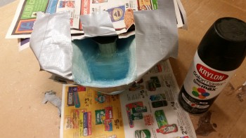
I taped up the nose cone to prevent any unwanted overspray.
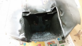
And then sprayed a couple of coats of flat black paint onto the sides and “ceiling” of the area that will show through the lens cover for the nose mounted landing light (aka “landing light bay”). In addition, before I remount the nose cone I’ll hit the vertical bulkhead wall immediately behind the landing light with a couple coats of this black paint as well.
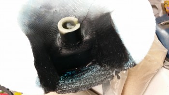
Here’s a shot of the painted nose cone “landing light bay” after the paint dried.
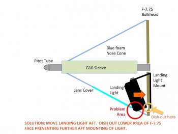
You may have noted in the pics of the nose cone that some of the foam at the bottom aft end is chipped away where I had to thin out the foam to allow for the nose cone to be remounted with the landing light in place. In actuality, it doesn’t fit. Due to the 11-14° down angle of the landing light required for landing in a Long-EZ, the front bottom corner of the light protrudes beyond the bottom profile line of the nose by about 0.2″.
Since I haven’t skinned the outside of the nose, I could easily account for this and simply modify the bottom nose structure to allow for this minor protrusion, but I don’t want to… mainly because of the drag implications, but also because the visual ones as well. I will do this if I have to as a measure of last resort if that what it takes to keep the landing light in this location, since it’s the best viable spot that I’ve come up with for my build. But clearly I’m going to do everything I can feasibly do to get this light mounted farther aft.
Here’s a diagram I made of the problem:
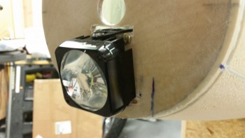
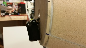
Here’s a couple shots of the landing light after I put spacers on between the aft side of the F-7.75 bulkhead and the landing light mount to move the mount, and thus the light, farther aft. If I could move the light up, which I can’t due to the pitot tube G10 sleeve, than this would resolve this issue as well. But my only option is to move the light assembly aft, which means the bottom aft corner of the light will have to occupy space that currently is the front face of the F-7.75 bulkhead.
I took my Dremel and grinded a channel that is perhaps about 0.1″ deep where the bottom aft corner of the light would contact the bulkhead. It still needs to go a bit farther back so I’ll continue to mess around with it until I get it dialed in. I also sanded off the 4 remnant blobs of 5-min glue & blue foam off the front face F-7.75.
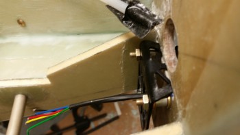
Here’s a shot of the back side of the F-7.75 bulkhead in the batter compartment with the 1/4″ aluminum spacers I inserted along with a couple thick washers to move the landing light aft. So far it’s made a noticeable difference, but it needs to go significantly farther aft (I’m thinking 0.4″) for the issue to be resolved. This may mandate modifying the landing light mounting bracket, or constructing a new mount altogether.
I plan on resolving the landing light mounting issue tomorrow so that I can get the nose cone remounted and move on to finishing the nose construction, which of course includes glassing the exterior nose skin.

