
I started off today by getting a bunch of paperwork in order: updated chapter to-do task lists and some powerpoint slide decks I keep on different big upcoming tasks like the strakes. This took a few hours, after which I headed down to the shop.
I was very pleased that with an ambient humidity reading of 36% in the shop . . .
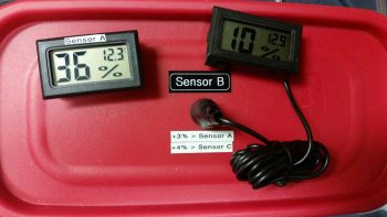
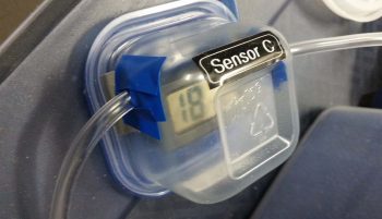
that my new engine dehydrator configuration yielded only 18% humidity internal to the engine! Now, that’s more like it! Anything under 30% is good and means minimal moisture in the engine, so obviously 18% is way better . . . that helps, but I still want to get this engine pickled soon.
 Part of the process (or at least my process) in prepping for installing the lower engine mount extrusions is to figure out where all the hell hole resident items go. I have a mount for the oil heat pump, and the laser altimeter for the nose gear’s new AEX system will reside on the bottom of the aircraft in the hell hole area, so the component most needing a home was the B&C SD-8 B/U Alternator relay.
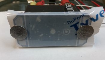
My initial thought was to have it on the aft side of the GIB seat back, where I’d use a click bond stud on one side and a RivNut on the other. However, to do either I needed to open up the slots on each end of the relay to accept a #10 screw.
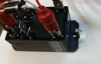
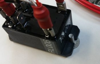
I used a 3/16″ drill bit first, then subsequently a 13/64″ drill bit, to open up & widen the slots on each end of the relay.
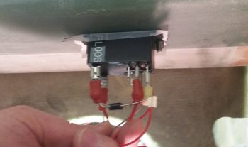
After poking, prodding, and probing around in the hell hole, I realized with all that was traversing through this busy area, and really wanting to keep components that can more easily get snagged away from the opening in the GIB seat (for cramming stuff into for much-needed storage during flights), I decided to place the SD-8 relay in pretty much the same spot that had once been ID’d for both the electric fuel pump and the GRT MAP sensor (both which have moved on to greener pastures): the bottom side of the CS spar.
I then taped up the bottom of the relay to protect it against any untoward glue-goobers, roughed up the face of each click bond (I can’t use a RivNut on the lower CS spar cap), then cleaned the click bond mating surfaces with Acetone…. making these babies ready for some 5 min glue!
Woah! As I was holding up the relay for a final location fit, I could visualize chunks of skin getting extracted from my forearm (accompanied by a stream of appropriate expletives) from the protruding click bond posts while I glassed in the lower engine mount extrusions. Since these click bonds can quite easily be glued/glassed in at a later time, I decided to table this exercise for a date AFTER the lower engine mount extrusions were installed.
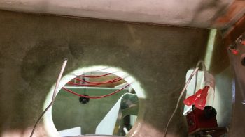
For about 6 years now, ever since I skinned the outside of the fuselage, I have dealt with the pair of coiled-up 1/8″ aluminum brake lines in the hell hole. Well, I hit another major milestone today in that I finally –after all these years– trimmed those suckers down to a manageable length. In the not too distant future I will complete the brake line runs from the wheel all the way to the master cylinders.
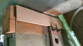
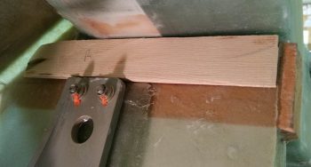
I then scrounged up the lower WA16 wedge shaped pieces of Spruce that make up the base for the lower engine mount extrusion glass. Just as on the top, these WA16 Spruce wedges serve to align the engine mount posts more parallel to aircraft centerline and less with the curved sides of the fuselage.
I had to trim the upper front corners of each one to get them to slide forward enough, but after a couple of trial and error rounds I got each side to fit in nicely. Since I will not be flipping the fuselage upside down to install these lower engine mount extrusions, I’m kicking around the idea of floxing these WA16s in place first with some peel ply over top to minimize the variables when I glass in the engine mount extrusion BID pads. We’ll see . . . more assessment & eval required.
Again, in prep for the upcoming lower engine mount extrusions installation, I had to temporarily evict another hell hole resident: the FT60 Red Cube fuel flow transducer. If it was just the Red Cube I may have considered just taping it up, but with it’s pesky wire pigtail and the fact that it needs a good wipe down before final install, I yanked it.
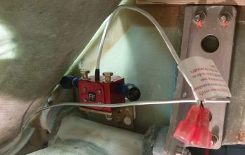
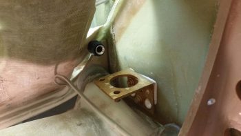
I’ll of course cover up the remaining fuel line and FT60 mounting bracket with protective tape during the lower engine mount extrusions install.
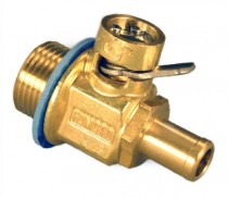
I then called it a night for shop work and did a bit more research on installing & safety-wiring my Fumoto engine oil quick drain valve. I also did a quick inventory on some more engine fittings and hardware for my upcoming monthly (apparently) ACS order.
With crazy snow forecasted for the next couple of days, I’ll continue to prep as much as possible for the lower engine mount extrusion install. Just as a point of note: these extrusion installs, followed by the engine mount itself getting installed and subsequently attached to the engine –to facility mounting the engine to the engine stand– is priority #1 at this point of the build.