Chapter 16/19/21- Right strake glassed

Today was huge as far as significant progress on my build.

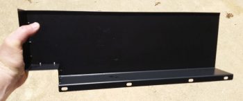
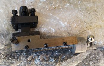
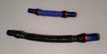
First, I started by gathering up my front control stick and right side pilot armrest to assess my control stick mounting angle.  Once again, the Cozy Girrrls make extremely high quality parts, but they have the name “Cozy” in their moniker for a reason (or did, as they are now finishing up a Long-EZ).

The Long-EZ plans say to lean the control stick tube in 5° at zero degrees/neutral ailerons and install.  However, with the slick Cozy’ish straddle-stylel control tube that I got from the Cozy Girrrls, it has what looks to be 12-15° slanting control stick mounting nub on the top with ailerons at neutral/0°.

I wanted to get the best angle both for flying comfort and also for left/right clearance both within the armrest, but also with the lower fuselage sidewall at full left aileron, and upper fuselage sidewall at full right aileron.  I decided to go with control aileron tubes pretty much centered which gives me about 12° inboard slant on the control stick.  Not too crazy really when you compare it 5°, and if it really becomes an issue I’ll just pull the control stick assembly, lop off the nub and practice my TIG welding!

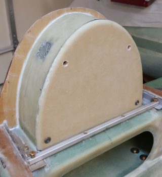
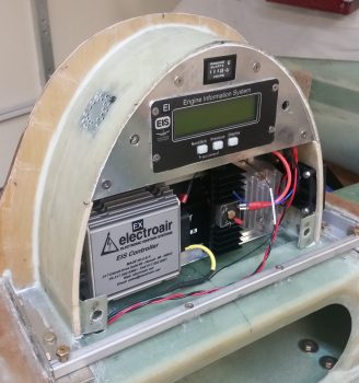
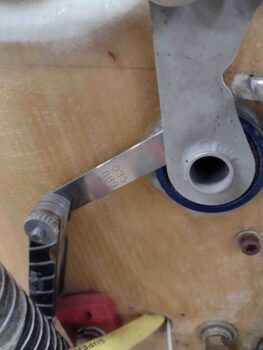
I wanted to also ensure I had at least 1/32″ clearance between the CS124 pivot and the firewall mounted bearing.  This gives me about 1/8″ clearance from rod end bolt heads to current firewall, and with a 1/16″ Fiberfrax going on before the 0.025″ Titanium sheet for final firewall install configuration, I should have plenty of room.

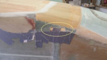
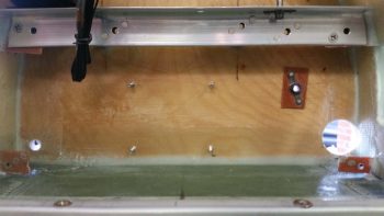
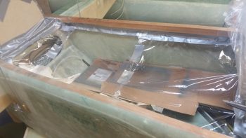
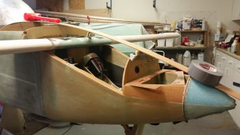
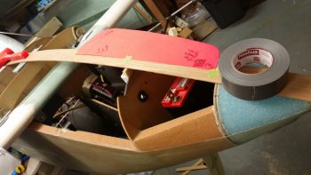
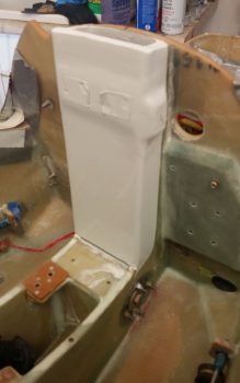
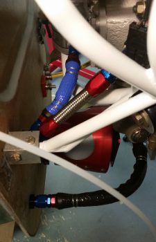
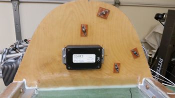
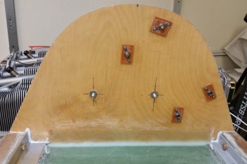
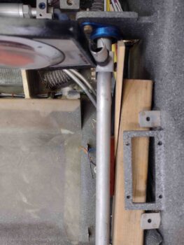
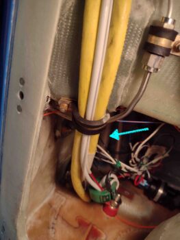
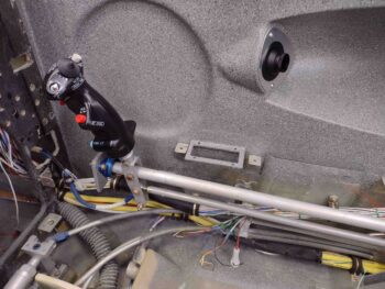
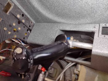
The crazy part of this adventure was getting into the very aptly named Hell Hole… boy did it live up to its namesake today!

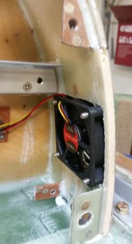
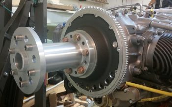
As you can (barely) see, the CS121/CS122 pair is buried in the upper right corner.

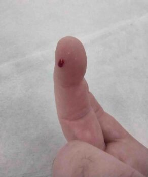
As an aside, I spent a good 15 minutes hunting down and sanding finger killers and vacuuming out the dust to avoid this… which happened mere minutes after ending my hunt for just such offending bits of glass.

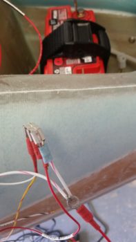
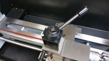
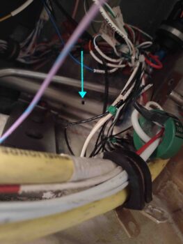
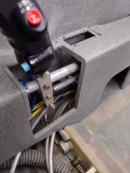
I tried in vain for a good 10 minutes to get my 90° tube drill jig up there onto the aileron control tube to drill a nice centered, perpendicular hole… but I didn’t have any clearance to get a clamp up there and I couldn’t get a good seating position to get both hands up there to wrap duct tape.

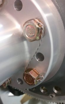
After sitting there for a couple minutes pondering how to make it work, I said “screw it!” and free hand drilled it with a 10″ long #12 drill bit.  After I broke through on the bottom side of the tube I did zip tie a small square to my drill bit to give me a close approximation to what 90° was.

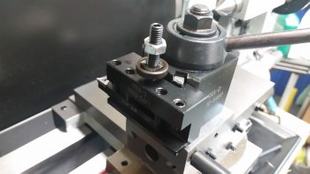
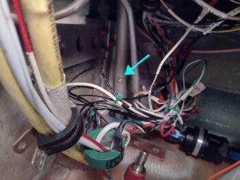
I tried installing the plans called out AN3-11A bolt from the top side of the tube, but we all know the story: there’s just no clearance between the tube and the bottom of the CS spar.  I am out of and had ordered —but not received yet— some AN3-10As so my next bolt in line was an AN3-7A.  Since my install is temporary at this point since the aforementioned firewall components need to get installed, I simply put a standard nut in for the time being.

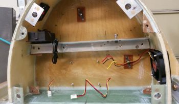
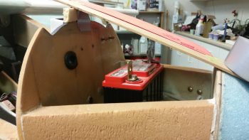
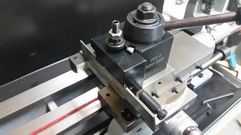
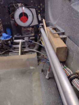
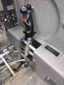
With my ailerons clamped at zero on the wings, this set my control stick at it’s new zero position as well.

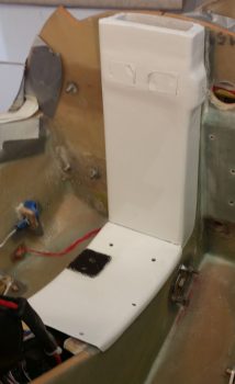
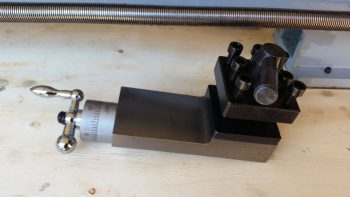
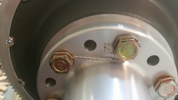
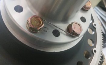
Here’s a top view of the pretty much vertically in line control tubes.

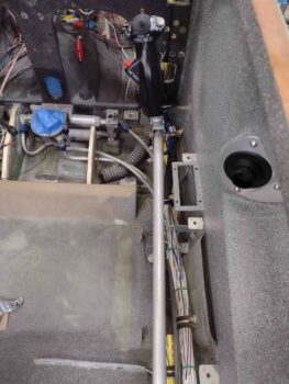
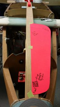
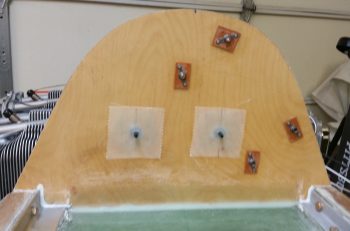
And a shot of the control tubes’ clearance within the armrest with ailerons at neutral.

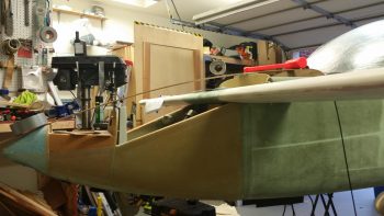
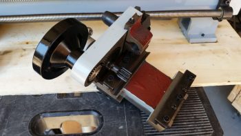
I then moved the control stick full left until the left CS128 bell crank hit the 20° up aileron hard stop.

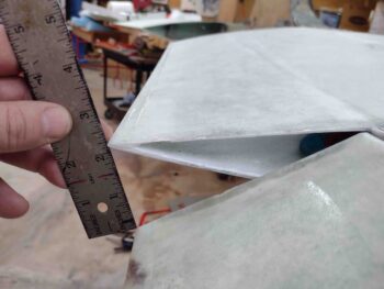
Bingo!  The aileron is right at 20° up (angle finder is at 160°) and my physical gap is a hair over 2″.  On the opposite right wing, the down aileron gap is over 2.1″, so looking good at the ailerons with full left stick.

And I have way too much room between bottom control stick and sidewall… it reminded me of when you attempt to barter with someone at a market in a foreign country and they accept your first offer.  Doh!  Could’ve been much less!  Well, here, the stick could be over another good 3/8″ providing more leg clearance in the plane… but full right aileron will complete the story.

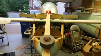
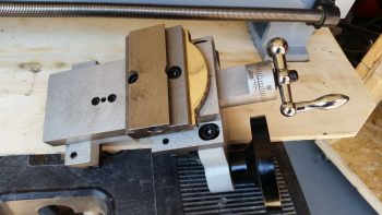
I then did the same exercise to the right: full right stick to the CS128 bell crank hard stop.

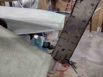
My down aileron gap on the opposite left wing is an unusually paltry —for down aileron— 2″.  Good enough, but often we canardians see 2.1-2.4″ down aileron gaps.  The up travel on the right aileron is about 20.4° with a 2.1″ gap between wing and aileron TEs, so I’m definitely ok here.

In fact, it’s probably good that I’m getting a bit over 20° up travel on the right because this is with the stick pegged against the sidewall.  The control stick edge and CS128 bell crank hard stop both physically hit when the control stick just kisses the sidewall.  Obviously during normal flying ops I’ll rarely notice these extremes.

Note how far inboard the bottom of the control stick protrudes just a bit past the armrest.  Not bad at all, but this would be going into either seat cushion or my thigh a little bit.  Whereas the full left aileron exercise would theoretically allow me to move the controls outboard, this is telling me that we’re in a good spot with this exact positioning, all things considering.

I’ll take it!  Task complete.

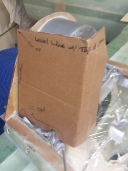
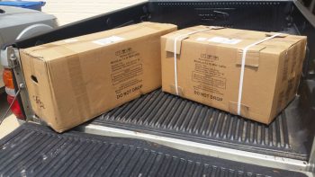
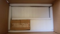
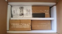
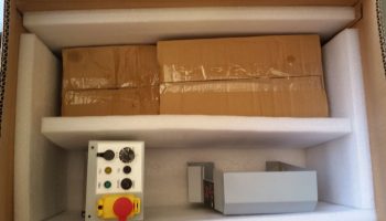
I thought late yesterday that I had received my roll of UNI that I ordered from ACS, but I unwrapped the plastic and paper to reveal it was actually the roll of BID I had added as a late addition to the order the next day. Hmmm?

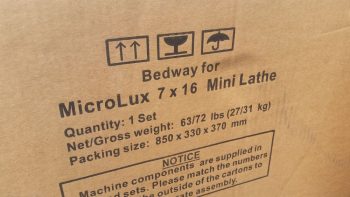
I checked my email and sure enough, the order with my UNI was out for delivery.  So I took a good hour plus break and grabbed some food before my next endeavor on this build.

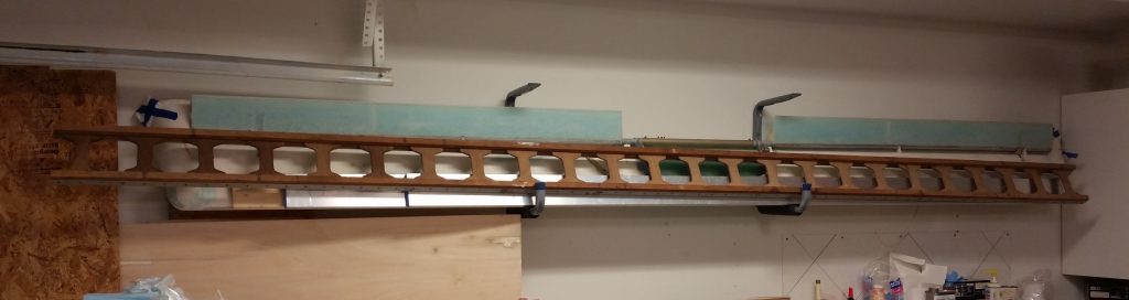
Once I got the UNI in hand, I cut Ply #1 for the right strake (sorry, still had the camera in stupid macro mode… ever since they updated my phone without permission the camera works slightly differently!).  This ply of UNI is parallel with the strake leading edge.

And then ply #2, which runs parallel to aircraft center line.

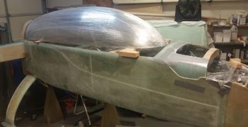
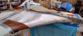
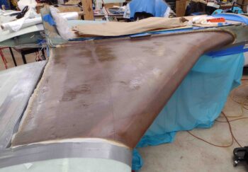
I then prepped the right strake top foam, seams and fillets with EZ Poxy micro and flox. Clearly I applied wet micro to the foam surfaces.  I’m using EZ Poxy here on the right strake top layup to finish up the last bit of E-Z 84B hardener.

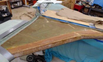
I laid up the first ply of UNI on the strake, with it being a bit more fiddly going on then I remembered with the strake bottom skin layups… but it ended up good.

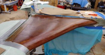
I then laid up UNI ply #2.

And wetted it out.  EZ Poxy really does have a beautiful look to it when it goes on.

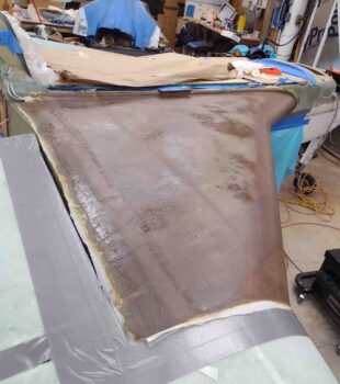
I then added the requisite ply #3, a 5″ diagonal strip of UNI.  I could argue that with my OD rib not in the plans position that this isn’t doing a whole lot for me, but what the hey, it’s one ply of UNI and I threw it on there just in case!

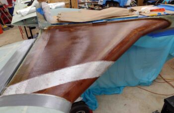
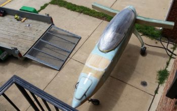
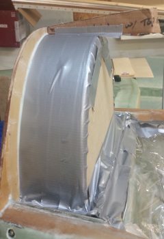
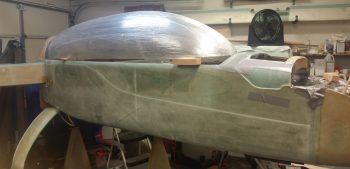
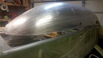
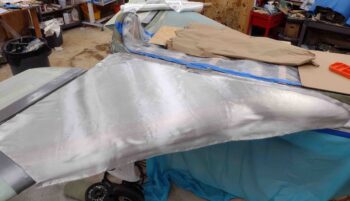
Here we have all the UNI plies laid up on the right strake top.

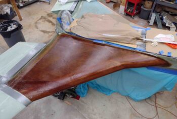
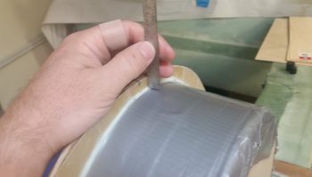
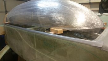
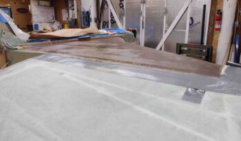
I followed a chapter out of Wayne Hicks’ build, although I don’t remember if he actually went through with it (or maybe it was Bernie Siu… who remembers these things. ha!) by adding peel ply to the entire strake top layup.  I know from the bottom strake surface it took about 2 hours to sand that nasty UNI in prep for micro finishing.

Well, admittedly it took a good hour getting this somewhat wrinkled (it’s been through many moves!!) peel ply applied, wetted out, squeegeed and stippled to remove all the air I could.

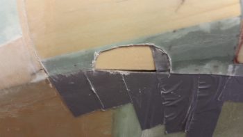
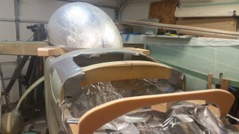
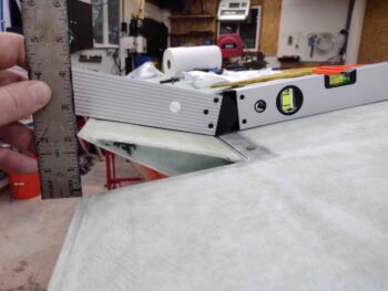
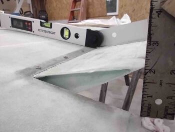
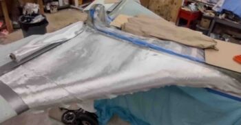
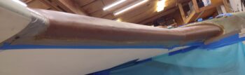
Here we have the strake leading edge with the new top glass overlapping it… which I’ll note that I am pretty darn happy with.

So that is the end of today’s adventure… that not surprisingly went well past midnight by the time I cleaned and tidied up the shop, turned out the lights and locked up.  Time for a glass of red wine!

Fuselage on Trailer!

Today was about loading up the fuselage on the trailer to haul it down to NC.

I started out by using the Fein saw to cut a notch on each side of the aft nose cover about midpoint where the openings for the canard will be located.  I then spent a few minutes digging out the foam to create a channel from one side to the other.  This channel will be used for transiting tie-downs through the nose.

I then spent a bit of time reconnecting the wiring (with the requisite bit of troubleshooting) for the nose gear system.

I then got to work rolling the fuselage out of the shop and positioning it into place for loading it onto the trailer.

I then wheeled the fuselage into position just on the edge of the trailer ramp, with all 3 wheels positioned so that the fuselage was on the trailer CL.

I then rolled the fuselage up into the trailer and secured it into place.

A few hours and one rainstorm later, I had the fuselage and canopy ready to roll!

With duct tape in all the right positions, I was ready to head off on my trek down to NC.

I’ll be down in NC over the weekend delivering the fuselage to its new home.  When I return my primary focus will be on the house to get it prepped to sell!


Moving the Build to NC

Just a quick update on the move since now it involves the Long-EZ project in large part. In fact, I’d say that about 70% of this haul down to North Carolina was Long-EZ related components, as you can tell in the pic below with all the boxes labeled with “LEZ” in large block red letters.

In addition to the strake leading edge kit, I also wrapped up and included the lower cowling among the components that were transported down to NC.  Also, the box on the very left of the pic above are the upper and lower winglets.

Moreover, since I had space in the trailer, and since it just barely fit (after trimming off about 3/8″ of the wing end rudder cable conduit), I strapped the right wing into place and hauled it down to NC as well.

This leaves the fuselage, left wing, canard and upper engine cowling as the last of the large aircraft components left up in Virginia.

If all goes according to plan, by the end of July pretty much the entire aircraft project will be down in NC.


Chapter 18 – Initial canopy prep

Today I started out by pulling the peel ply and cleaning up the layups securing the GIB headrest to the fuselage, specifically to the front side of the firewall and sitting atop the CS Spar.  Rest assured this was no quick effort, and took well over an hour to complete.

I then attached the headrest cover in place with the lower 2 CAMLOCs (Late last night I figured out the stud lengths I need to acquire for the top set) and was quite pleased at the fit and finish of the cover.

As I was trimming the internal headrest layups, I mounted stuff to make sure it all fit.  Here I test mounted the cooling fan after removing a decent sized piece of glass overhanging the bottom edge of the fan notch in the sidewall.  I also took the opportunity to test out the length of the new SS CS mounting screws I picked up for its installation.

With both fans installed, I also took the opportunity to reallocate some wire from the smaller exhaust cooling fan to the larger intake cooling fan to allow the latter’s wires to reach the right-side mounted fan controller.

I then spent a bit of time doing some final assessments and measuring before I pulled the trigger and drilled the firewall pass-thrus in the lower outboard corners of the GIB headrest.

I had some errands to run and a few personal things to get done, so while I was out I picked up some more hardware for the headrest components.  When I returned I installed just about everything in the headrest for the first time all together.

I then test fitted the front cover with ALL the components inside… still fit like a champ!

I wasn’t able to fit the set of the fuel probe control heads into the GIB headrest structure… yet.  Simply due to lack of space.

However, looking inside the fuel probe control boxes I noted that the control board is fairly small compared to the actual box its mounted inside.  I’m thinking I may remount the control board in a smaller form factor that would allow these units to be mounted inside the GIB headrest…. since it really would make for easier wiring, integration, etc.

Since the GIB headrest is pretty much finished I had to say goodbye to some old friends that have been hanging around since 2012.  I made these guys up to check fitting and configuration on the GIB headrest internals long before I really had anything other than the basic airframe components on hand.  These guys sure have been useful over the years, but I certainly don’t have a need for them anymore since the real versions are on hand and installed in the fuselage!

I then taped up the GIB headrest and immediate surrounding area in prep for canopy installation/construction/glassing.

As I did on the front fuselage side, I also covered up the back seat area with clear plastic to minimize any canopy build nasties getting on anything.

I then noted that I forgot all about the top cowling angle template that I had made up out of cardboard.  Now that the GIB headrest was in place I could no longer set the top cowling angle template in place.

I decided on a simple fix to remedy my oversight, and started by measuring the distance from the top of the headrest to the top edge of the firewall: 0.5″.

I then transferred that dimension over to the cardboard template and cut it at a right angle to match the top line of the GIB headrest which is 90° perpendicular to the firewall.  Voila! Now I have my top cowling angle denoted for the canopy build once again.

I then spent the next couple of hours just getting a feel for the canopy and how it sat free form on the top of the fuselage.  I took a myriad of measurements, checked height, checked width, checked length, and checked clearances forward and aft . . . all to get a good understanding of how the canopy would best fit onto the fuselage.  BTW, I included both pics below since they’re at different angles.

I then grabbed a quick shot from the front.

Then, after finalizing a few decisions, I did the initial taping of both the right and left longerons.

Tomorrow will be all canopy and nose from this point forward.  There is a ton of stuff to do to be sure to get both the nose and canopy constructed over next week, but I think I can get most if not all of ‘er done!


Chapter 13 – Nose job

I started off today working on my AC unit for a couple of hours.

I then got around to some wet sanding and painting on the oil “tower” box lid, and then some wet sanding and clear coating on the box portion itself…. both endeavors were rife with annoying issues and the outcome of each one is yet to be determined.  I suspect that there is a fair more work to get the surfaces dialed in to an acceptable (not perfect!) level.

Today was really more of a research & modeling day to tie together all the loose ends and integration questions I had regarding the nose.  I set up the canopy in its near-final configuration and then got to work on the nose.  I took a fair amount of notes and changed my hand drawn plans to account for the finalized dimensions, angles and curves.

Some outstanding questions I answered was that, A) I’m extending the height of F28 0.4″ at the center line, and B)  I installed (with duct tape) a 0.9″ gap-filling piece to account for the depression in the Napster bulkhead.  When the nose is final this gapped area will be filled by the thickness of the nose hatch.

It may be a bit hard to get an exact idea with the big roll of duct tape on the nose, but this is outline of the upper nose.

Here’s a shot for the left side.  This provides a better depiction of the nose’s top curve.

And a shot from the front.

I then taped in place the nose hatch template (which is currently only half the hatch) to assess its size, shape, accessibility, etc.  As a point of note, the dimensions and shape of this particular nose hatch template is based off the Berkut nose hatch…. at least it started out that way!

I then set the battery in place to ensure it would fit.

Regarding the battery, I assessed topside cable clearance and clearance for removing and installing the battery.  The PC680 battery is around 7.1″ wide and my nose hatch at the narrowest point above the battery with this shape and configuration would be 7.8″ wide.

Here’s a shot of the left side nose hatch template taped in place.

The above is somewhat of a quick overview of my planning process.  Again, I took a myriad of measurements, checked angles and clearances, then made quite a few notes and annotated drawings and pics I have of my nose design.  There are a number of things that I will cover as I build since it would difficult to provide overviews without pictures of the components and build process.

One such area –that happens to need correcting– is the very front top corners of the fuselage where each side intersects with F28.  I’ll cover that tomorrow as I go through the process of remedying my 6-year old error.


Chapter 3/22/23 – Back at it!

I just returned from my North Carolina sortie late this afternoon.  I of course had to attend to some normal life stuff before getting back into the groove of things.

I would like to actually start out by reporting on a couple things I did/noted before I left for NC.  The first is that before I left out I flipped the engine inverted and recharged the cylinder dehydrator plugs with fresh desiccant.  Since I have 4 of the these dehydrator plugs I removed them from the top plug holes on the cylinders and replaced them with standard aircraft spark plugs before flipping the engine upside down. [This is a previous “stock” pic I took of the engine positioned inverted on the engine stand… it’s mislabeled stating that it was inverted only for a few hours vs 5 days].

After replacing the desiccant in the dehydrator plugs I then pulled the 4 standard aircraft plugs on the bottom of each cylinder (of course facing up at this point) and replaced them with the dehydrator plugs.  Since the oil filler cap was facing downward and the top mounted crankcase vent would leak into the Engine Dehumidifier air lines if I tried to attach it to the inverted engine, I just left both unconnected for the duration of my trip.

In addition, as I was packing up for taking a load of household stuff down to NC, I found my cardboard mockup of the Trig TT22 transponder.  It became readily apparent why I thought the actual TT22 unit was much smaller than I expected as I realized why when I compared the two.  The dimensions for the TT22 unit are given from the tip of antenna jack to the end of the wire mounting spring clip on the other end.  Clearly the box section of the unit is not included in those dimensions, making it much smaller in real life than my mockup.  Just an observation I had in how there always seems to be some sort of wrinkle in the planning of this stuff for the aircraft build.

So I got back home late this afternoon from NC and immediately kicked off an overdue Seattle Avionics chart data update for the GRT HXr EFIS (I missed the previous one… ).

In addition, the desiccant I left in the oven while I was gone was clearly saturated with moisture and had turned a bright light pink, so I fired up the oven to refresh the desiccant to its desired brilliant blue state.  A while later, after letting it cool a bit, I put it back into a sealed container to use in the Engine Dehumidifier after I flip the engine upright tomorrow.

Also upon returning home I found that some packages had arrived, including a digital tachometer and project box (to mount it in) from Ebay for the lathe.  Since I had to make a Home Depot/Lowe’s run I decided to do a quick check of the upcoming tach install to ensure I had all the components I would need on hand…. which I didn’t so I ginned up a list.  While I was at it I spent another 20 minutes mounting the lathe Quick Change Tool Post (QCTP) onto the lathe compound/cross slide/carriage.

Once the heights of the various lathe turning/cutting tools are dialed in, the QCTP will allow me to swap out tools in literally seconds vs tens of minutes.  Below are examples of a parting (“cut-off”) tool [top] and a turning tool [bottom], each in their respective tool holder [the attached tools are from a cheaper carbide tipped “indexable” tool kit I picked up from Harbor Freight, since it had good reviews…. I’ll use these tools as part of my kit starting out so if/when I break them during initial lathe ops, my cost of learning will be cheaper!].

Late this evening I did some final updates on my nose and canopy build task lists and printed those off in prep for starting back on these builds tomorrow.


Chapter 3/13 – Tooling up…again?!

Knowing that my lathe was getting delivered today and that I needed to sign for it, I started by opening up the shop and got busy wet sanding the very front NG30 mini-bulkhead that I clear coated last night.

After wet sanding it I buffed it out with rubbing compound and then hit it with a couple coats of polish.  It’s not perfect by any means but I think it will look great as a part of the white center NG30 “console”.

Then the UPS guy showed up with my lathe.  Which came in 2 separate boxes. [I’ll warn you now that the rest of this blog post pertains to the lathe, so if you’re not interested you can shut this down now…. cheers!]

Yep!  It’s a lathe!

Two big benefits of getting this specific lathe was that A) it was actually in stock, and B) the reports on it NOT being delivered in a mangled, unrecognizable container were non-existent.  In fact, the feedback was that it was packed VERY well for shipping (Two boxes vs just one greatly verified that fact).

Box #1 contained the main body: the headstock and the bed (aka rails).  It also contained the chip pan.

I then pulled the rather heavy headstock and bed assembly out of box #1, still mounted to its wood shipping mount plate.

I then opened up Box #2.  Words can’t express how pleased I was with the packing quality of these components.  The foam here was not cheap styrofoam, and the overpacking was just off the charts.

Box #1 of Box #2 was the gear cover that mounts to the left end of the lathe to cover all the gearing on that end.  Now, the motor is a direct belt drive configuration, but the ancillary lead screw drive and threading is gear driven.

Here’s the outside of the left end gear cover.

Box #2 of Box #2 was the electronics box.

The outside of the electronics box is the front of the lathe and the top is the control panel.

Then there was the odd components: the rubber mounting feet brackets and bag of accessories.

A closeup of all the threading gears in the bag of accessories.  This bag also included all the hardware and handles.

The rear back splash was honestly the only “free’ floating component packed in Box #2.

With all that stuff that came out, and there was still 2 boxes left to go in Box #2.

And again, the overpacking and protection was spot on!

One of the boxes contained the Compound slide with the old style tool holder attached (this will get swapped out for a quick change tool holder).

The top view of the Compound assembly.

Here’s the cross-slide assembly underside.

And the top side of the cross-slide assembly.

And let’s not forget the 3″ chuck (that I’ll most likely never use).

Here we have the headstock, the bed, the tailstock, the compound and cross slide.  I should note that as all these metal parts were unboxed I cleaned them with solvent.

I then flipped the headstock and bed upside down to remove the wood shipping mount plate.

And then mounted the chip bed and feet assemblies.

I then set the lathe assembly in place on the work bench.

And started wiring up the electronics box.

A closer shot of the electrical wiring getting connected out of the electronics box.

As I was checking the operations manual I ran across a template with the dimensions spelled out to hard mount the lathe to the bench.  I liked this idea much better so I removed the rubber feet and spent well over an hour (my issues, not the machine’s) getting it mounted to the bench.  In the end, I like this configuration MUCH better… a lot more stable.

To see the lathe in action and overview of my latest tooling up, I created a fairly short video:

This will be the last post I make for almost a week as I pack up another load to head down to North Carolina.  For any curious types out there, I should be down in NC by the end of the summer.  After settling in I plan to stop offering up these silly excuses as to why my plane is not finished yet!


Chapter 3/13 – Trimming up Dolly

I actually started this project a couple of days ago and finished it today.  Instead of stringing you along like I normally do, I just decided to show you what I was up to all in one whack!

I noted yesterday that my TIG welder was the “Elephant” in the middle of the shop, when in fact a truer statement would be that the fuselage dolly, having served its purpose well, is now the true elephant in the shop.  Not only do I need to trim it down for space, but I need to repurpose it as a portable tool work bench for my upcoming focus on making some bric-a-brac for the plane.

I started by clearing off the top of the fuselage dolly and then giving it a good cleaning.

I then removed all the hardware and wood brackets off the top.

Here’s the last official pic of the fuselage dolly before it got a massive makeover (key some dramatic music from some crazy reality TV show!).

I determined yesterday that I need the top to be 38″ long, while the width will remain a hair over 30″.  After determining the top area that would remain, I started on each end, cut and then removed the top shelf pieces and the underlying support frames.

I then removed the 4 corner slide posts that would get reattached, and then trimmed the remaining overhanging wood support rails from the table top.

About 2 hours later I ended up with a much shorter version of the fuselage dolly that again, will now be used as a portable work bench that power tools will get mounted to.

I mounted 2 recent acquisitions –the red 9″ Skil band saw and the Harbor Freight bench top combo sanding belt and disc machine– along with my ever faithful bench top grinder that has never really had a home.  Yes, I know that these tools don’t get high marks for being the best in their respective classes, and I’m sure they got beat up a lot in tool high school, but by all accounts they work well enough to do what I’ll need them to and moreover, they were cheap (like me!).

You may have noted there is a spot on the opposite side of the table, which is for a mystery tool that for now we’ll call: Tool X.  It is vitally important that the information as to the type and purpose of this tool not be made public at this time…. especially to Marco! haha!

My initial plan for the day was to wet sand and then clear coat the front NG30 mini-bulkhead so that I could have then wet sanded and buffed that out either later this evening or tomorrow, but alas I broke through the topcoat when I was wet sanding and had to repaint those areas with another couple coats of white paint.

Finally, much later in the evening I was able to successfully wet sand the white top coat and then clear coat it with a tack coat and then 2 full coats of clear.  Yes, I understand that these pics probably look exactly the same as the gloss white top coats…. but trust me, THAT’S clear coat on there!

I was remiss in getting a pic of the Oil “tower” box with its surface sanded down, before primer… after nearly an hour’s worth of sanding on the stubborn surface.

I toyed with the idea of using a bit of metal glaze body filler first but then decided I would not only use the primer as a bit of a guide coat per se, but also let it sit for a week to really cure while I’m down on my next trip to North Carolina.  For certain it will need some help in the hole-filling department, especially that crater on the north face, but I determined that it would probably be easier to do after the primer was on, cured and wet sanded.

My build tasks will be minimal tomorrow since I have to get into packing mode (which I was supposed to do today!) to prep my next load out of household goods to haul down to NC.


Chapter 21/23 – Wired . . .

I started out today with kind of a fun little project: assembling the engine stand that I picked up at Harbor Freight with a 20% off coupon.  As I was assembling it, a note in the instructions caught my eye: “Not for use with Aircraft” . . . hmmmm?

I also set the lengths of angled steel on the top and bottom mounts to provide an idea of how those will mount to both the engine stand and the engine mount (this angled steel was one of the pieces that Marco cut for me on his ginormous metal band cutting saw… which cut through this stuff like butter!).

I then did about 2 hours worth of spring cleaning in the shop to get it a little squared away for all the upcoming activity.

Next, although I didn’t get a pic, I mounted the right wheel pant.  I noted some trimming I’ll have to do on the wheel opening, but it’s seriously on the order of about a 1/16th of an inch.  That will get it in line with the opening dimensions spelled out by Gary Hertzler.  In addition, I took some measurements on the right wheel pant that I had already taken on the left.  The conclusion was that the wheel pants match perfectly from the gear leg forward to the front pant tip.  However, from the TE of the gear leg to the back tip of the wheel pant the right one is about 3/16″ farther aft, or maybe I should say 3/16″ longer.  No big deal and it was more of a curiosity thing than anything… I can tweak it a bit when I finish the wheel pants.

I then set my sights on mounting the 8″ prop extension to the flywheel and the engine prop flange.  It took about a half hour, a block of wood and a bunch of medium strength taps with a rubber mallet to get that sucker seated to within about 0.1″ of the flywheel. Then I very gently tightened all the bolts to get the prop extension to seat tightly against the flywheel.

Then, as per Sam’s (from Saber Manufacturing) directions, I torqued the 6 prop extension, prop flange and flywheel bolts to 50 ft-lbs each.

I then safety wired the bolts in pairs using 0.041″ stainless steel safety wire.

This is my first go at safety wiring, so if anybody out there sees anything disagreeable, please give me a shout.  I’m always open to constructive criticism.  Of course, I’ll have my EAA chapter bubbas look at the build as well.

Here’s the final shot of the installed prop extension.  Let me tell ya, the only time this thing is getting removed is when the alternator belt needs replaced! [Tomorrow I’ll test mount the prop and of course will take some pics… so I figured I would get the prop extension install out of the way today].

It was getting later in the evening, so I decided to relax and watch some TV while I played with my new toy: a ClampTite tool.  I removed and brought the fuel line and oil heat oil line with me upstairs.

Then, using the Clamptite tool (another first for me), I fire sleeved the 2 hoses.  Note that I’m using blue fire sleeve for fuel lines and black fire sleeve for oil.

As I’ve seen on Joe Caraggio’s site and others, there seems to be a requirement out there (or at least a good idea) to seal up the ends of the fire sleeve so the wool-type lining doesn’t soak up any stray oil, fuel, or what have you.  I had some of the expensive gray 3M fire barrier on hand so I decided to seal up the ends with that.

Here I’ve applied the 3M Fire Barrier to the ends of each fire sleeved hose….

However, I’m not a big fan of how the gritty, blotchy gray Hi-Temp RTV ends looked, so I cut a narrow piece of heat shrink and covered the RTV’d ends up…ahh, much better!

My final build act of the evening was to simply reinstall the hoses back onto the engine.  I definitely think the fire sleeving will work and I’m glad I went this route.

Tomorrow is picture day and my next door neighbor will be using his Uber awesome digital camera to get some nice aft end pics of my Long-EZ build.  Once that happens, my next goal will be to get the engine off the fuselage and onto the engine stand.  I’ll then drop all my engine focused shenanigans and will start on finishing up the nose and getting the canopy built.


Chapter 16/23 – Lathing about

Marco, his wife Gina, and I all attended a very nice memorial service for a fellow Canardian, Walter Grantz, who sadly went West a few weeks ago.  Marco spoke at the memorial and told some wonderful stories of our friend Walter, who will be missed greatly.

The next day Marco and I had the privilege of helping Walter’s son, Art, and grandson, Christian, remove the wings off of Walter’s Long-EZ to ready it for transport down to NC State University, since his beloved Long-EZ is being donated as a static display for the university’s Engineering Department.  During the time we spent at Walter’s hangar, Art was kind enough to give me Walter’s long level board that Walter had used to build his Long-EZ back in the 1980’s.  It will truly be an honor for me to use it when I build the strakes, and here it is hanging on my shop wall.

Later that evening, Marco was gracious enough to do a bit of machining for my build and lathed the midpoint quick disconnect insert bar on what will be my new elevator control tube [If you remember, I drilled an “extra” hole in my other one and didn’t want to fly with it with an unnecessary hole that only would serve to weaken a critical flight control component.  Moreover, Chris Seats gave me some info and components to help me upgrade to a 5/8″ diameter tube vs the 1/2″ stock… not that the stock version is deficient, it just happened to be easier for me to build a 5/8″ version].

Marco lathed the midpoint quick disconnect insert bar from a 5/8″ rod of 2024 aluminum down to just a bit of over a half inch in diameter.  We also cut it to length to allow for not only the quick disconnect clevis pin(s) & rivets to be mounted, but also long enough that the new (and correct) pitch trim actuator connecting hole will now be drilled through both the control tube and the lower side of the quick disconnect insert bar… clearly a much stronger mounting hole since it will be solid metal for the entire width of the hole. (Sorry… I don’t currently have any pics of these parts, but I should in the next day or so…)

After we got the more important elevator control tube out of the way (we also cut the new 5/8″ control tube pieces to length), we then cut two 1 foot lengths of 6061 3/8″ rods into 3 lengths that fit in-between the mounting tabs of my oil cooler.

Marco then used the lathe to drill out a 3/16″ hole down the center of each one of the oil cooler mounting spacers.

Here are the 6 oil cooler mounting spacers with holes drilled to accept AN3 sized mounting bolts.

Here are the top 3 oil cooler mounting spacers set in place, with the middle one mocked up with an AN3-41A mounting bolt.

And here are another couple shots with the top 3 oil cooler mounting spacers in place with a test fit of an AN3-41A mounting bolt.

Of course Marco did an outstanding job on all the parts he machined/lathed for me (Thanks Brother!).

I wanted to get some glass curing overnight after I got home from Marco’s, so I spent a good half hour figuring out the best spacing and mounting for the 2 MAP sensor boxes… one for the GRT EIS and the other for the Electroair EI.

Originally I had planned on mounting them both vertically, but when I assessed the internal configuration and best spacing within the GIB headrest/D-Deck area, I decided to place them both mounted horizontally, as the GRT MAP sensor is below (with the Clickbonds 5 min glued in place).  The Electroair EI MAP sensor box will get mounted directly below the GRT MAP sensor box.

After letting the 5-min glue cure about 10 minutes, I then removed the GRT MAP sensor box.  I cleaned up the excess 5 min glue and sanded around each of the Clickbonds.

I then laid up 2-plies of BID over each Clickbond, peel plied them both, and then left them alone to cure.

I should note that Marco also used his big metal cutting bandsaw to cut up a 36″ piece of angle iron that I will use to weld up a mount that will allow the engine mount to be connected to the engine stand.  Over the next few days I’ll be getting that ready to go as well, after I get just a bit more data from having the engine mounted.