Chapter 13/22 – Surprise visit!

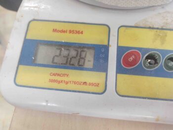
I started out this morning compiling a much needed and much overdue order for Aircraft Spruce.  I did an inventory of my EZ-Poxy resin for the upcoming strake build and discovered I only had about half a gallon left from my GIB thigh support fuel sump build. So I pulled the trigger on another gallon just to be on the safe side.  I also bought a few more SkyBolt (CAMLOC) receptacles for securing the aft nose/avionics cover and the AN3 bolts to secure the canopy safety catch (SC-1 . . . finally!).

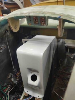
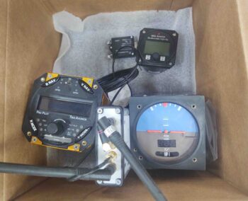
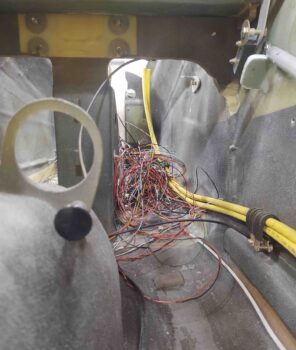
Lastly, in order to get the cockpit area prepped for paint I need to have on hand and install the ELT antenna (most likely right behind the pilot’s seat), so I figured it was time to order the ACK E-04 ELT and get those components here for final assessment, configuration and install.

Upon coming back in the house with all the data I gained during my workshop recon I noted that I had a missed call from Marco.  By the time I called him back he was at his airport on high alert ready to launch on a high priority sortee to . . . ?  Here!  Wow… ok. (He called the other day and said he was looking to hop down here for a short visit when the WX was good… and today was a beautiful Fall day).

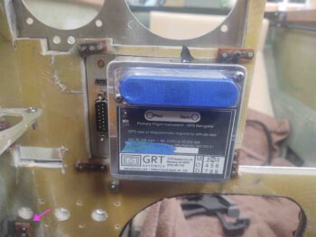
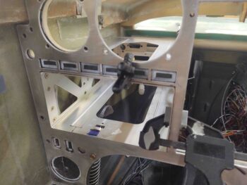
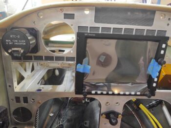
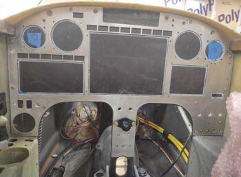
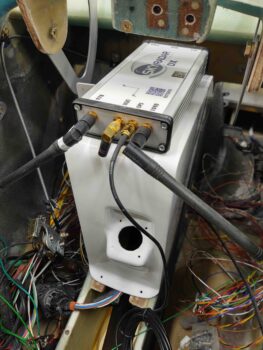
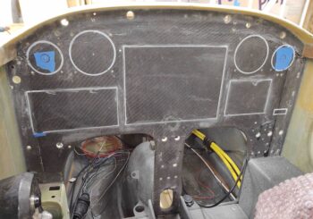
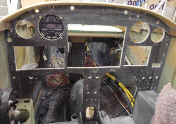
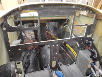
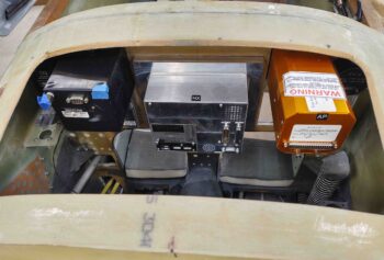
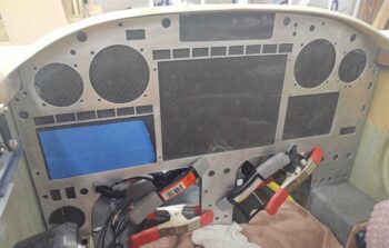
While he was getting airborne I ran out to the shop and threw all the avionics and instruments into the panel, including the GNS-480 GPS.

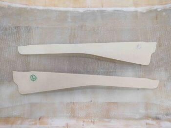
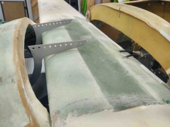
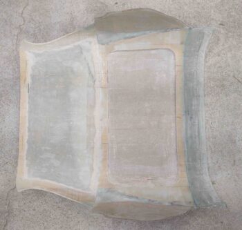
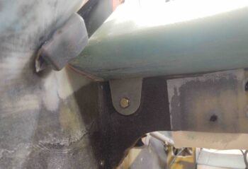
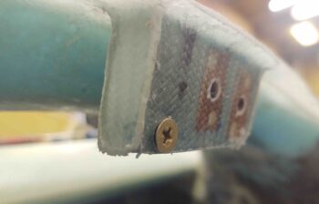
I had also started my initial cleanup on the aft nose/avionics cover hinge tabs, so I finished those up post haste and put the cover back on the nose.

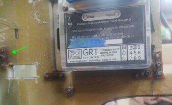
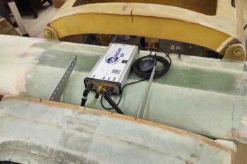
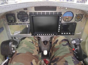
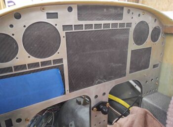
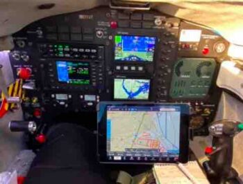
BTW, here’s Marco’s recently updated and quite awesome new panel in his flying EZ, JT:

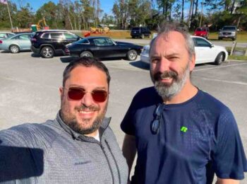
When I picked Marco up from the airport, we took the requisite selfie for Terry Lamp! (grin)

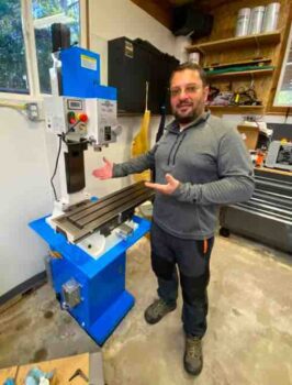
At the workshop, Marco started his inspecti … uh, tour.  Here he is telling me everything I could ever want to know about MY milling machine (hehe).

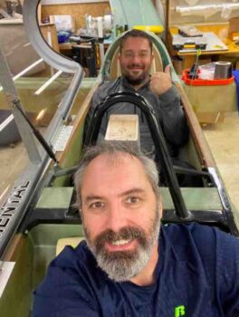
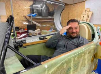
We then checked out the build.  He tested out the front seat and then while he was in the back I climbed in for another selfie.  It really was great to have him down here… it’s been over a couple years now since he’s seen the build.

Overcome with awe and sheer respect for the quality of my build (haha) Marco was rendered speechless, and could only offer up his respects with an inspiring, perfectly executed salute!

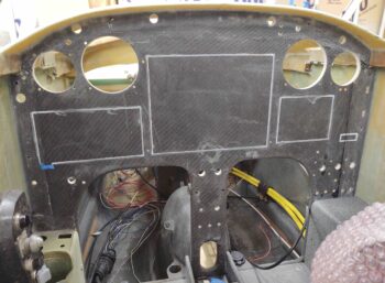
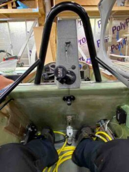
Marco snapped this shot from the back seat looking forward.

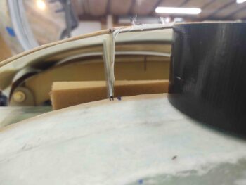
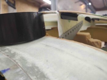
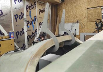
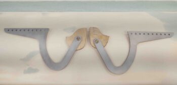
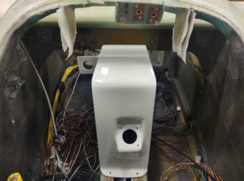
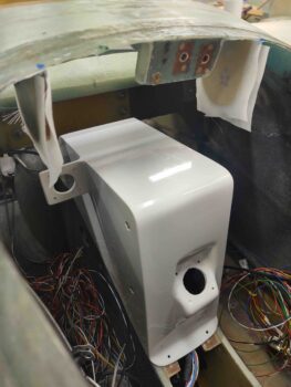
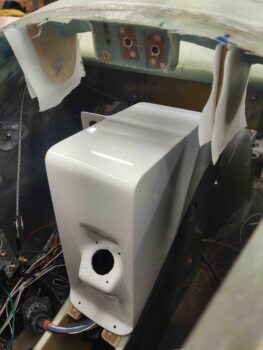
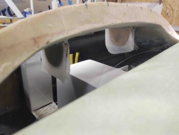
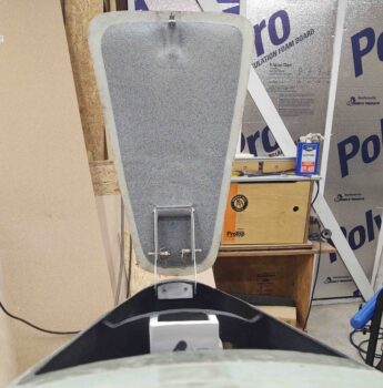
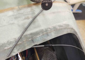
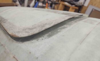
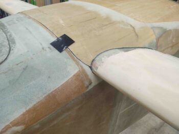
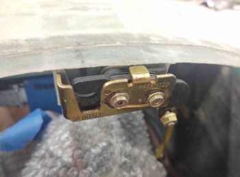
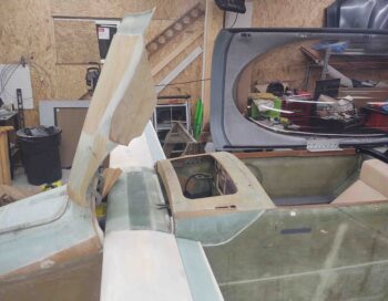
After I dropped Marco off back at the airport and he departed (amid a buzz of onlookers talking about ‘that’ odd airplane . . . ) I returned to the shop and got back to work on the aft nose/avionics cover.  I was FINALLY able to dial in the hinge configuration and get those suckers mounted.  Here we have the aft nose/avionics cover in its MG-inspired open position.

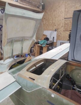
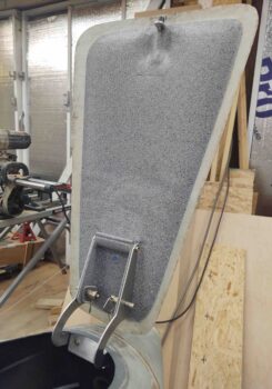
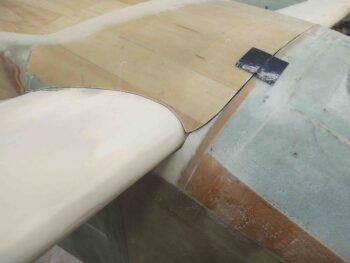
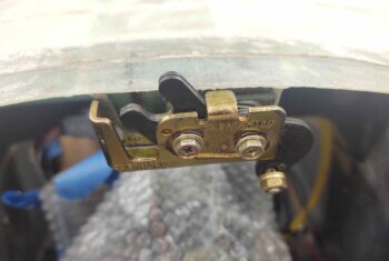
Another shot of the aft nose/avionics cover in the open position.

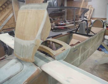
And one last shot . . .

As I work on the aft nose/avionics cover I plan on spending a good hour each day knocking out a section of the panel to get it so the components are all installed and I can prime, paint, label and clear this sucker.

Since the heavy lifting is complete with the install of the main avionics, I’ve mentally broken down the sections to be completed as follows: the lower left corner, followed by the center strut, the lower right corner, the mid-section, the upper section, and then all the Korey lights: GNS-480 annunciators and panel ON/OFF indicators.

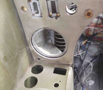
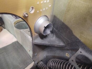
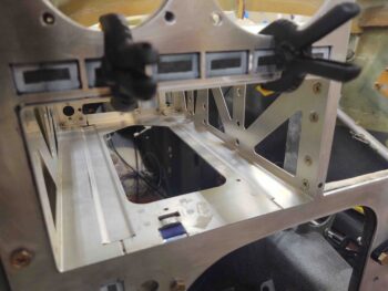
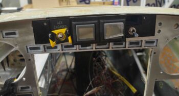
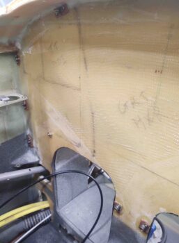
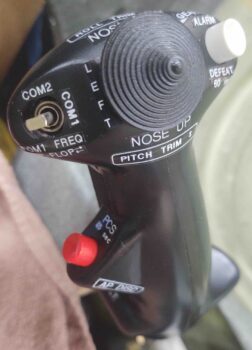
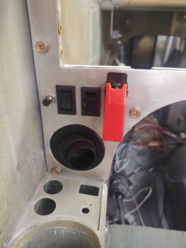
Thus, today was the first to be completed of all those sections: the lower left corner.  Here we have the eyeball air vent installed, the outboard oil cooler switches installed, the RAM air open/closed rocker switch installed, and the red flip covered fuel pump switch installed. To be clear, installing these switches meant clearing out a good bit of material on the back (nose) side of the original composite panel bulkhead.

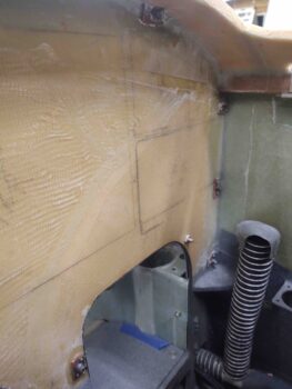
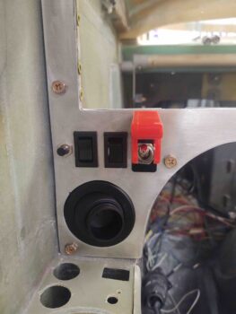
Another shot of the fuel pump switch in the ON position.

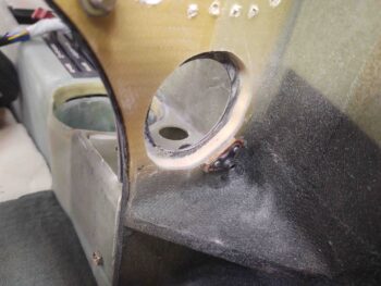
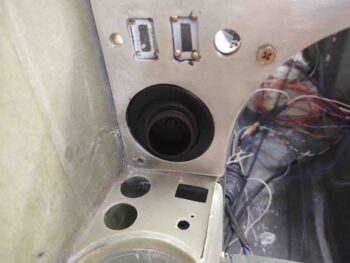
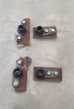
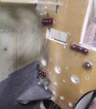
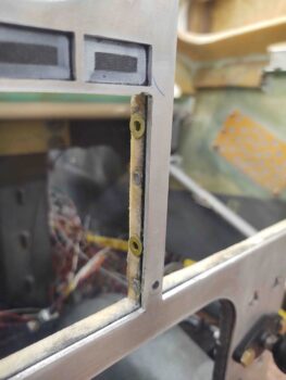
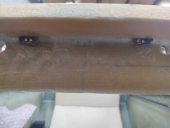
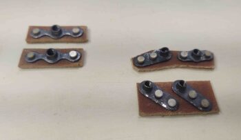
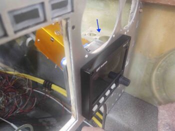
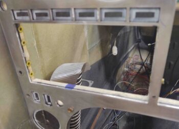
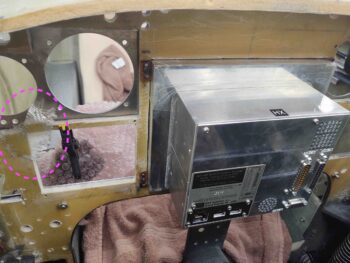
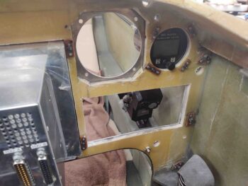
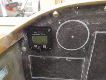
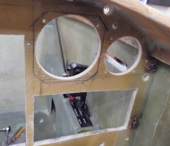
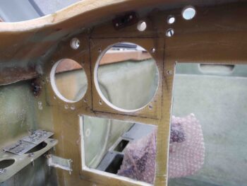
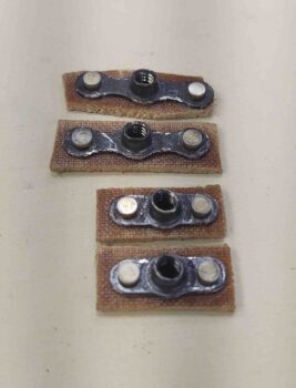
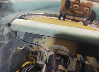
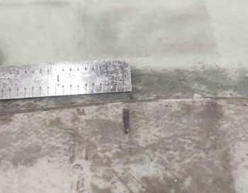
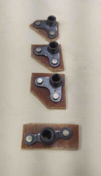
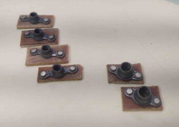
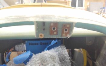
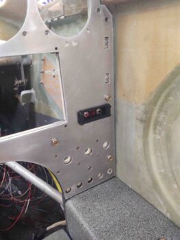
My last task of the evening was slightly increasing the size of the opening on both the aluminum and composite panels to accommodate the ELT remote head to be mounted externally on the face of aluminum panel.  I drilled the four 4-40 holes through both panel structures, and tomorrow I’ll flox in the phenolic nutplate assemblies to secure the screws.

With the aft nose/avionics cover hinges installed I expect the pace of the remainder of the cover install to accelerate a bit.  I will still be concurrently installing the panel components, but over the next week I expect both to be complete as I transition into the strake build (with a few other build tasks sprinkled in as well).


Chapter 13/22 – Panel Black Hole!

I oftentimes like to do an added extra task that’s off script and not on the day’s task list. Well, today I was curious if I had a 2″ hole saw that I would need to install the panel mounted eyeball air vent.  Rootin’ around in the garage I found my old hole saw kit and it had a 2″ diameter bit.

I decided it probably wouldn’t take that long, so curiosity got the better of me and I fairly quickly drilled out the hole(s) for the eyeball vent.

A couple things on this configuration.  First, I don’t actually have the vent mounted on the aluminum panel face.  If I remove the aluminum panel, it simply slides off around the eyeball vent.  This leads to point #2: the exterior diameter of the vent is 2″ (actually closer to 2.1″).  However, the mounting diameter on the interior (silver colored) and exterior (black) pieces is 1-3/4″.

To do this, I started with the 2″ hole saw from the back of the panel (nose) and drilled towards the face of the panel (tail).  I carefully closed in on the glass on the front face of the composite panel bulkhead and then stopped just short of it.  Then I drilled from the face of the panel toward the backside (again, nose) using the 1-3/4″ hole saw.

I needed to make the ~2″ side just a bit wider in diameter so I used my Dremel Tool with a sanding drum for no more than a minute.  It probably took longer to vacuum the mess up then it did drilling and Dremeling it all.

And here’s the mounted eyeball vent.  Remember, the panel will be black as well so the seam around the edge won’t be hardly noticeable.

Here’s the back view ….

I then removed the 2 offending perimeter nutplates on the right side of the panel.  I got busy making up 2 more nutplate assemblies to replace the ones I just ripped out… which took a fair bit of pounding (boy, this flox stuff really works eh?!)

I then floxed the new nutplate assemblies into place.

I had also prepped the 3 new RivNuts for the inboard/right side that will secure the GNS-480 mounting tube.  Since their strip of panel on this side is narrower than the RivNuts are deep, I decided that on 2 of them I would keep the top flange and trim off some of the back side (where more threads are), while on the other 2 I would cut the top side off and gain about 1/8″ more thread.

As I did on the outboard side yesterday, I waited a couple of hours until the flox “greened” and then installed the GNS-480 mounting tube and secured it in place with the screws. BTW, once the flox fully cures this officially finalizes the install of all my major panel instruments.

Before I closed off access behind the panel for a while by glassing the aft nose/avionics cover hinge tabs, I mounted the top 2 screws that secure the warning annunciation sub-panel to the top center of the panel.

Here are the 2x #6 nutplates for the warning annunciator sub-panel top screws.  I need these in place to assess spacing for the aft nose/avionics cover tabs that will sit outboard of these nutplates and be secured by CAMLOCs.  You can see the panel CAMLOC holes on each edge of the pic.

I then spent a bit of time transferring my cardboard templates for the aft nose/avionics cover hinge tabs onto the 1/16″ thick G10 plate, and then cutting them out on the bandsaw.

After a number of test fits and adjustments, I glassed the hinge tabs to the underside of the aft nose/avionics cover with 2-plies of BID on the inboard edge of the tabs.  I then set the cover in place and aligned the outboard edges of the hinge tabs with the hinges to ensure everything was peachy-keen.

I then made up another pair of #6 nutplate assemblies for the warning annunciator sub-panel lower screw holes (L – I mounted these later in the evening, but failed to get a pic of them in place).  I also made up a couple of double 4-40 nutplates for mounting the ELT remote head (R).  This round of nutplate assemblies pretty much does it for the panel, at least at this point in time.

After making nutplates and floxing some in, and also doing an assessment on my CAMLOC situ for the aft nose/avionics cover, I then laid up 2 plies of BID on outboard side of the hinge tabs.

I peel plied those as well and left them to cure overnight.


Chapter 13/22 – A little bit of that…

I started off today by pulling the peel ply and cleaning up the layup on the aft nose/avionics cover.

I then left to run some of the errands that I didn’t complete yesterday.

A few hours later I got busy making up 4x 4-40 phenolic nutplate assemblies for mounting the GRT Mini-X EFIS.  After some prep work I then floxed the 4 nutplate assemblies into place.

A bit later as I was poking around the aft side the panel figuring stuff out (still…) I noted that I will need to replace the 2 lower perimeter nutplate assemblies on the right side of the panel due to clearance issues (with remote EFIS USB and P-Mag ignition switch).  I added a magenta arrow in the lower left corner of the pic to show the lowest of the offending nutplates.

Here we have the bottom two 4-40 nutplate assemblies floxed in place that will secure the Mini-X to the panel.

In addition, I included a green arrow on the left side of the pic to show the second oftending nutplate that must be extricated and replaced.

Here’s a shot of the front side of the Mini-X as it serves as a screw placement template for the 4x 4-40 nutplates floxed in place.

Just over the top of the Mini-X you can see I added a blue arrow pointing at an electrical connector bracket… ah yes, this must be relocated a bit higher and slightly forward as well for everything to fit.  Yep, we’re definitely getting to the nitty-gritty details stage of the game where apparently everything has to fit… ha! (Also note that I installed the autopilot pitch servo to ensure the spacing is good when I move that bracket).

Once I got the Mini-X squared away and the nutplate flox curing, and checked a few configuration/spacing items (as noted above), I drilled and prepped 4 holes on the outboard edge of the composite bulkhead panel opening for the GNS-480 GPS mounting tube.  I then prepped and carefully floxed in 4 RivNuts to match the mounting holes on the outboard side of the GNS-480 mounting tube.

I also drilled and prepped the 4 opposite/inboard side mounting tube screw holes as well. I was only planning on floxing in the 4 outboard RivNuts to start, but since I had enough flox left over for one more RivNut I quickly prepped another one and mounted it on the inboard side.

I waited a couple of hours for the flox to “green” so that it was firm and sticky, but had enough body to let me secure the screws in place.  If I had any slight alignment issues, the not yet cured flox would give a little to conform to the screw pattern.

Also, to ensure the weight of the GNS-480 mounting tube didn’t pivot front end down, I clamped it in place.

I then spent a couple of hours dialing in the hinge attach tabs for the aft nose/avionics cover.  I had planned on cutting and glassing these in tonight, but by the time I got done with all the nitnoy measuring, aligning, spacing, designing, etc. it was just too late.

Here’s the G10 plate that I’ll cut these things out of first thing tomorrow and glass them up.

I’m hoping by tomorrow evening I’ll have the aft nose/avionics cover mounted to the hinges and operational in that regard.


Chapter 13/22 – Nuggin’ panel install

While awaiting my G10/phenolic to get delivered to start work back on the aft nose/ avionics cover (more on that below), I decided to get some panel components installed.

My main goal was the HXr, which I had already made up the 4x #6 nutplate assemblies. Before I started I was going to make up the #4 nutplate assemblies for the Mini-X EFIS, but found as I was drilling out the mounting screw holes (which I overlooked when I drilled all the panel holes) that the top right corner (left in pic) was cracked.  There just wasn’t enough meat at the corner so my drilling caused it to snap right through.  Not good if I want a 4th screw to secure my Mini-X.

So my plan on floxing in nutplates changed to also laying up a 2-ply patch to that corner (denoted by magenta circle).

I was actually halfway through making up the #4 nutplates when I remembered I forgot to drill the Mini-X holes (which I discovered last night as I was mounting all the panel components).  I then figured I would simply use the #4 nutplates I was working on to mount the MGL clock/timer, which I could do concurrently with the HXr –I couldn’t do that with the Mini-X due to clearance/access issues.

As you can see, I realized I wouldn’t really be able to get to the outboard screws, or at least see them well, so I just flipped the MGL clock/timer around backwards to still get the correct spacing on the screws.  Looks odd but worked a treat.

Below is another shot of the HXr EFIS and MGL clock/timer from the front side of the panel.  However, the more important item in this pic is the Garmin GNS-480 GPS mounting tube in place. It took just a few minutes sanding down the edge of the composite panel bulkhead to get it to fit, but it does fit… and well!

A point of note: what didn’t take “just a few minutes,” but rather over half an hour, was simply removing all the wiring connectors off the back of the GNS-480 mounting tube… what a hassle!  Crazy difficult job for what should seem like an EZ little one.

Moreover, speaking of seemingly EZ jobs: between making up the #4 nutplates and sanding down the edges of the #6 nutplates to fit close enough to the HXr EFIS, this entire endeavor took over 2-1/2 hours to complete!

One area I’m extremely pleased with is the fit of the GNS-480 mounting tube.  The back outboard corner (upper right in pic below) is a good 0.150″ off the side wall, which means I was able to drive the GPS unit far over to the left, very close to the sidewall and still obtain good clearance on the side.

Today and tonight really was another heavy planning and coordination work day.  I don’t have any pics, but I was going to mount my ELT remote head under the aluminum panel and embedded into the composite panel, until I gathered it up to test the spacing. Then, upon looking at it I remembered it has a battery that will need replacing every so often. Even if it’s every 5 years I don’t want to have to remove the entire panel just to change a battery –not worth it– so I decided to mount it externally on the face of the aluminum panel.  This means, yep, another four 4-40 nutplates on the list!

I also assessed spacing for my WxWorx XM satellite radio weather receiver, and am happy to report it appears that it will fit just fine top centerline just forward of the panel.  I’ll show more when I get to installing it.

I went out for dinner to take a break after sanding the pour foam on the aft nose/avionics cover down (for about 45 minutes) so that it was level with the surrounding surface on the interior side of the cover.  I then vacuumed it, and cleaned off the bare glass spots for receiving glass.

Upon returning home, I got to work making a large paper template to then cut a single ply of BID to cover from the wood lip just aft of the big pour foam area (left in pic) all the way to the front edge (right in pic).  I micro’d the foam and also around the edges of the forward bare glass area where it is bordered by wood (and some glass).

I laid up the 1 ply of BID and then peel plied most of the edges… and 2x 3″ strips in the forward bare glass area where the hinge brackets will be mounted.

Yep, this “simple” 1-ply layup took about 3 hours!

I was also going to make up the 4x #4 nutplates for the Mini-X panel mount, but after this grueling layup (I know, laughable!) I decided to have a glass of wine and pen this captivating blog post instead!  Cheers.


Chapter 13/22 – Nose?? Nah, panel!

I started out today by trimming the aft nose/avionics cover hinge brackets that I installed and glassed last night.

I noted that the hinge configuration worked best with both of them each mounted on the right side.  It allows the left hinge to open up more fully, closer in line with the right hinge. And it allows the right hinge to better clear the electrical wire bundle traversing along the upper right side of the NG30 cover.

As I posted last night, I ensured the hinges would fit and function with the NG30 cover in place.  I’m thinking that’s the first time I’ve installed the NG30 cover since the top of the nose was completed and also with the canard in place.

I was remiss in not accounting for how much G10/phenolic I had on hand, so I just ordered a big piece last night to make the hinge brackets for the cover. I need to work the hinges first before most everything else since the swing and settling-in of the aft cover into place will dictate the configuration of most of the other securing points.  I’ll of course work what I can until the G10 arrives.  Which may mean I get a lot of panel work done!

Here you can see the aft nose/avionics cover hinges saluting.

I’m pretty much done with the nose-side aft nose cover hinge brackets, except for trimming them down in size a bit now that I know I don’t need to move the hinge pivot holes.

The hinges aren’t perfectly aligned since the priority was maximized clearance with the canard on the outer edge of the hinge curve, and the top corner of the nose (cross “bridge” piece forward of canard) for the sharp corner of the hinge.  There was very little wiggle room before the hinge was either scraping on the canard LE or else unable to travel forward due to snagging on the corner of the nose cross piece.  Since the nose isn’t perfect in curvature, and definitely doesn’t have a uniformly curved underside, combined with my forcing an equidistant measurement from centerline, they are off from each other in max opening height and overall elevation… but I don’t see why they won’t still work as designed and I’m very pleased with how they’ve turned out so far.

I started my panel work by drilling out all the small round holes for switches, CAMLOCs, etc. Since I have 6 aft nose/avionics cover attach points across the top of the panel: 4x CAMLOCs and 2x hinge pin passthrough/threaded attach in the corner by each longeron, I figured I would drill the other panel component holes while I was in drilling mode.

I then got busy trimming down the remaining excess weight on the aft nose/avionics cover.

Not bad… it started at a hair under 4.1 lbs when I pulled it off the nose, and now it’s around 2.3 lbs: a 44% reduction in weight.  Again, I think it will be around 2.5 lbs when installed.

On one of my trips to the house, I stopped and grabbed a box full of goodies.

For YEARS the plan has been to mount to the Radenna SkyRadar ADS-B In Receiver on the top of the NG30 cover.  But as I was looking at the cover, then the space on top of the canard, I could see no reason why not just mount it on the canard and keep the NG30 cover nice and clean.

So that’s the new plan.  And here is the new mounting location for the ADS-B receiver.  I already checked that all the cables will reach it just fine.

I then got back to work on the panel.  I took a white paint marker and marked the interior perimeter of all the major avionics (and the ELT remote head).  Also, before I removed the aluminum panel I ran the Fein saw along the inside edge of the rectangular avionics to score the face of the old panel bulkhead.

I started with the 2-1/4″ hole saw and cut out the hole for the MGL clock/timer.  This one is easy because I like this guy mounted with the case on top of the panel.  However, it did highlight to me that I need to make 4 more 4-40 nutplate assemblies to mount it.

Of course I also used a 3-1/8″ hole saw to cut the bigger holes for the autopilot and ADI.

Here I’ve cut the middle row of holes: the GNS-480 GPS, HXr EFIS, and Mini-X EFIS.  In addition, you can see I then mounted the Trio Autopilot.

I then marked around the Trio autopilot, essentially using it as a template.

And cut out the mark for the autopilot.  I then installed the TruTrak ADI and did the same thing.

Here you can see I’ve removed the ADI and am ready to cut out the square.  Hopefully this is obvious that I’m mounting these instruments straight to the back side of the aluminum panel, so they need to completely pass through the old composite panel bulkhead.

My last instrument to cut the perimeter through the old composite panel bulkhead was the vertical card compass.  It sits so close to the ADI that I just cut straight through the right side of the ADI cutout to make a cutout for the compass.

Of course I couldn’t resist climbing into the cockpit and making some airplane noises after I got the panel assembled with a good bit of instruments. I am super happy with how the panel is coming along… I really love the layout and functionality of all the components.

BTW, here’s a shot of the components from behind the panel… note how much access the top open area under the aft nose/avionics cover provides.

My last task for the evening was to fill the aft depression on the underside of the aft nose/avionics cover with pour foam.  Surprisingly, it took me 3 whole sessions to get this area filled.  I’ll trim and sand down the foam and prep it for the 1 ply of BID I plan on laying up over the areas that I essentially strip mined for weight reduction.

And with that, I’m calling it a night.


Chapter 13/22 – More hinge brackets!

Today I actually started out updating my control stick electrical diagram and connector pinout doc… it took me a while because there was a logic hurdle I just couldn’t get past with the new configuration –knowing that it worked because I tested it!  But after I drew it out I realized what was going on and was able to finish.  Whew… I felt like I was back in college doing higher level math!

I then went to the shop and dove into testing a myriad of hinge configurations, placements, spacings, etc. for well over an hour before finally getting to the task of cutting out the aft nose/avionics cover hinge mounting brackets out of 1/4″ thick Birch plywood (same as the firewall).  Which also took well over an hour cutting and dialing in the bracket fit and hinge geometry.

These brackets are a bit tricky because they have an “ogee” type curve from front to back, but also a side-to-side angle on top to match the curve of the upper inside nose.

Thankfully I had the foresight to test out the fit of the hinges with the NG30 cover before I did the final mount of these hinge brackets.

I had them placed where they are below at the outset, but then moved them a good 1.5″ inboard on each side.  However, the right hand hinge (left in pic) would have been slamming into the cable bundle that will run along the upper right side of the NG30 cover, the visible bracket being part of the bundle [seriously, a ton of the wires in that cable bundle will be what is currently in that rats nest on the nose floor].  I then had to move the hinges back outboard to my original targeted spot to provide the required clearance.  I think it will also make it easier to get the NG30 cover in and out when required, which won’t be often (hopefully!).

I then set each hinge bracket with 5 min glue with the hinge actually installed on the bracket. I taped a speed square to the canard to help ensure I kept each hinge and bracket vertical, or at least acceptably close.

I then glassed each side of each hinge bracket with 3 plies of BID.  If you look closely, you can see multiple hinge pin holes that I drilled as I was dialing in the hinge geometry.  I simply filled all but the correct hole in with flox just prior to laying up the glass.

Here’s another shot of the aft nose/avionics cover hinge brackets from the aft side, just over the canard.

And a final side shot of the hinge brackets.

My final task of the evening was making up 4 each #6 nutplate assemblies for mounting the HXr EFIS to the panel.

Tomorrow I have some errands to run, which will make a dent in my build day.  But I will try to do what I can on the continued push to finish the aft nose/avionics cover install.


Chapter 13/22 – Door latch cable

With the nose hatch door paint good and the clear coat on and intact, I mounted the door to the hinges… here’s a couple shots.

I then got busy installing a click bond with 3-plies of glass over it on the front face of F22, and a RivNut on the upper side wall (held in place by clamp) to allow me to mount Adel clamps when routing the nose hatch door latch cable.

I then carefully trimmed the nose hatch door latch pull cable to length with my Dremel tool…

. . . routed the cable and terminated it at the door hatch latch arm.

This is a view of the nose hatch latch pull handle.  Pardon the bundle of wires behind the cable pull handle… that’s why I have wire labels and electrical diagrams! ha!

Here’s the nose hatch door and nose centerline (top) marks.  The nose hatch door is latching about 1/16th to the right (left in pic).  Doesn’t seem like much, but considering it skews how the nose hatch door sits in the “pocket” created by the lip and surrounding flange, I’m going to dial it in to move it back to centerline.

Like I mentioned before, the nice thing about this style of latch is that when you “pop the lid” it gives you a nice raised hatch door to grab ahold of to open it up.

With the nose hatch latch technically complete, I moved on to floxing in all the instrument panel securing nutplates: 10 total.  The 2 nutplates on the center strut are 1/4″, while all the others are #10.

Here’s the other side.  After around 6 hours cure time (fast hardener) I removed each screw, cleaned it, and then re-installed it.  I didn’t want to check these floxed-in nutplates tomorrow simply to have a screw permanently floxed into it, although I did apply a thin coat of grease to all the screws before installing.

My last task of the evening was to swap out to connector wires on the control stick P5 connector to actually complete the physical swap of the autopilot disconnect and the gear/canopy alarm defeat buttons.

The diagram underneath the cable and connector is a 2-page sheet I have for each connector.  The first page gives me general information about the connector.

The second page gives me specific pin-out information for each side of the connector. These things are lifesavers if kept up to date and the info is current, which is why I’m so maniacal about keeping all my wiring diagrams up to date.

Here I’ve cracked open the connector to gain access to the wires and sockets.

Then, using the black tool shown in the pics above, I pulled the wires/sockets I was looking for.  I then swapped them out and did a continuity check on them to ensure I had them correct… and all was good.  This made the swap of the AP Disconnect and Alarm Defeat buttons on the control stick officially complete.

(I also did a quick continuity check on all the other circuits as well and they all looked good).

I then put it back together.  It’s ready for operations!

I then packed it in for the night.  I know I keep saying it, but I really am getting closer to getting that aft nose/avionics cover installed!


Chapter 22 – Panel mounted

Although I wrote out a long to-do list over my morning coffee, today ended up being more of a planning day with some thoughts on final installs in the cockpit… such as throttle and mixture cables, fire extinguisher and GIB chargers, light switches, etc.

Although my very first thing today was to run out to the shop and shoot the nose hatch door interior surface with a couple coats of clear.

A number of hours later, after it had seemingly cured, I started to tape off the painted area to hit the edge with some rubberized black paint to provide a minimal sealing effect.  Well, when I went to readjust the painters tape it ripped up a decent chunk of my good paint.

Back to square one.  I taped off the edge again and spritzed the damaged areas with enough paint to hide the damage.  [Way later in the evening I hit it with 2 more coats of clear and set it aside to get a really good cure].

I then grabbed the instrument panel and climbed inside the plane.  I noted all the edges and the center strut alignment with the panel.  To be clear, this thing is not perfect nor does it fit like a glove.  It will however look great and be completely functional for what I need, and I doubt when it’s installed the gaps on the sides or the slightly offset center strut will barely be noticed.

I started with the big 1/4″ bolts first with the RAM ball mount towards the top of the center strut.  Once those were installed and tight, I checked alignments and gaps all the way around again.  I then started drilling all the perimeter #10 holes.

Tomorrow I’ll start floxing in the nutplates for these screws/bolts…. which I made up 4 more assemblies tonight.

I will also try to get some work done on the aft nose/avionics cover… although I can’t promise much since I’ll be watching my friend’s kid for a while tomorrow.  Probably more critter-catching vs plane building for quite a few hours.

Chapter 13 – Sometimes crooked ain’t

I had printed out some new labels for the control stick yesterday, so first thing today I got them off the work bench and on the control stick so they wouldn’t get lost… here it is. Not much difference, but a few smaller labels (e.g. “COM1”).

I then got to work making up a new nose hatch door striker bracket.  Actually I tried filling in the hole with a weld on the old test one… but clearly my aluminum welding is not up to snuff because even though I followed the amps-required reference card, I didn’t even get to 2 seconds before the tab was obliterated… I digress.

Here’s the new bracket with a new straight striker.  I realized not only was the hole off-center on the previous one, but the first striker tube was slightly canted to one side. Noting that, I cleaned the ends of this one up on the lathe.

And then spent a good 15 minutes testing it out.  All looked good, and centerline seemed the place to be.

I then did final preps for glass, floxed it in place and laid up 5 plies of glass over it to secure it to the inside nose hatch door.

I needed a bit more epoxy, and went to make some more up in the original cup I had been using.  Well, my tip on the jug was all wrong and I ended with 3x more than I was looking for.  I didn’t want to pour it back in the jug since there was some previously mixed epoxy in the cup (a trace amount, but still some).  So after a quick think I decided I would knock out glassing the bottom of the oil box that will get mounted in the nose area… a nose to-do task needing completing.

I cut up some 1/4″ birch plywood squares and embedded them in the foam for some bolt hard points, and also created a flox corner all the way around the perimeter (although I used flocro to limit weight). I then laid up 2 plies of BID on the bottom of the oil box.

I was getting ready to head over to spend a couple hours with my little buddy, and still had just a bit of epoxy left.  I needed to also install a RivNut on the nose hatch door in the vicinity of the hinges to attach the aircraft hinge pins to so they wouldn’t be loose when not securing the hinges to the nose hatch door.

I floxed the RivNut in place in the hole I drilled, and then weighed it down with my 5-pound sledge hammer.  I then took off to go hang out with my friends for a bit.

Upon returning back to the shop, I cleaned up the flox around the RivNut… which turned out nice.

I also pulled the peel ply and cleaned up the nose hatch door striker bracket layup.

I’ll explain it more in a video where I can show the geometry, but the short story is that I ended up putting the previous (yes, canted) striker back in place to obtain a better alignment.  Yes, I did test the new straight one out around a dozen times, but the previous striker just aligns better when the nose hatch locks into place…. these builds can have some strange twists to them.  So in this case, crooked is straight!

I then taped off the edge of the interior nose hatch door, the striker tab and the outboard hinge tabs and primed, then painted the door.

In between the coats of primer and paint, I made up a couple 1/4″ (AN4) and four 3/16″ (AN3) nutplate assemblies for mounting the aluminum panel to the existing composite panel structure.  Tomorrow I’ll make up another batch as well.

Tomorrow I also plan on routing the nose hatch door latch pull cable and ensuring the front nose hatch door latch is fully operational.  Then I plan on focusing solely on getting the aft nose and avionics cover mounted.


Chapter 13 – Long-EZ Heartlight

I started out today laying up a few plies of glass along each side edge of the nose hatch latch mounting plate (pic below) to add a bit of strength to it.

I then let that cure while I slowly trimmed the front corners of the aft nose/avionics cover to fairly closely match the added fuselage corners in front of the canard LE.

With my initial fitting task out of the way, it was now time to enroll the aft nose/avionics cover into “fat camp.”  Yep, when I took this thing off it originally weighed in at just a hair under 4.1 lbs.  Pretty chunky for a cover.

I hatched the areas that would be losing glass and wood, leaving only the exterior glass.

At the state of the cover above, it weighed in at 3.9 lbs.

After 2+ hours of work, it looked like this.  Note there’s still a decent sized chunk of glass and wood in the lower left corner –as situated in this pic– that still needs to come out.

This is tough work, so my goal was to stop for the night when I removed a pound of weigh off the cover.  Well, I exceeded that goal by a bit.

Removing the last segment that I ID’d for removal with the hatch marks will most likely drop the overall weight of the cover down below 2.5 lbs.

I was hoping for sub-2 lbs, but I don’t think it’s going to happen.  Moreover, I’ll be adding some weight back in with a couple plies of glass and all the attachment tabs, hardware, etc.  So the final weight of this cover will be in the ballpark of about 2.5 lbs, my best educated guess at this point.

I also had a few oopses and broke through the surface in around 4 spots.  The glass in this area is particularly thin, maybe 2 plies thick, because it was the final top finish.

For fun I turned off most of the shop lights and chucked an LED work light into the avionics bay.  Looks pretty cool with that thin cover glass.

By this point my glassed nose latch mounting plate was cured, so I trimmed and cleaned up the layups.  I also cleaned out the holes in the nutplates and drilled a #10 hole in the flox hardpoint for the adel clamp screw.

Here’s a shot from the front with the nose hatch latch mounting plate ready for action…

I then mounted the nose hatch latch.  Here it is in the close/locked position.

And here we have it in the open/unlocked position.

I was ready to move forward with floxing and glassing my striker plate onto the nose hatch door, but the material I was going to use for the bracket just wasn’t up to snuff (I glassed a hefty 9-ply angle bracket) compared to my test/mockup bracket I’ve been using to dial in the latch… however, in my haste I drilled the hole off center in the test striker bracket.

That alone isn’t causing all the issues, but it’s leading to other alignment/mounting issues so I need to either weld the hole in and re-drill, or cut a new angle bracket for the striker.

However, I did do a good amount of testing on the striker configuration and I’m pleased with how this latch setup will function.

With my night cut short due to a change in striker plans (it was too late to fire up cutting saws, etc.), I came back in the house and spent nearly an hour updating my electrical system wiring diagrams in CAD.

I plan on getting the striker situation squared away first thing tomorrow and get the striker bracket floxed and glassed onto the nose hatch door ASAP.