Chapter 18 – Canopy, my canopy!

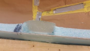
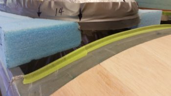
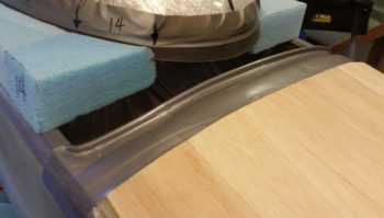
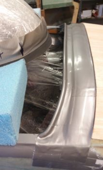
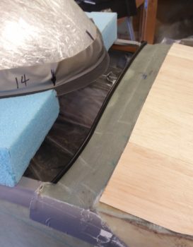
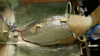
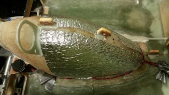
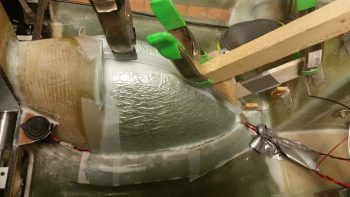
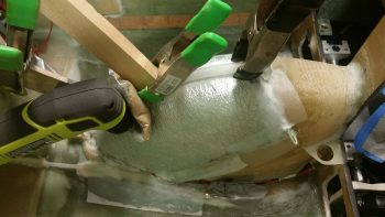
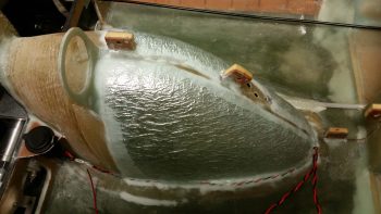
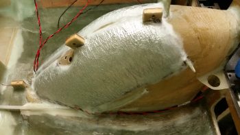
I should note starting off that it took me a bit of research and thought yesterday to figure out that I needed what was essentially an interior “wall” to retain the wet flox & BID that goes into all the component hard points on the canopy frame.  Thus the reason for a layup of 2-3 plies of BID –above and beyond the normal layup schedule– at each hardpoint location.

I started off today with another long round of more refined clean up of the canopy frame.  I Dremelled off a lot of dead micro, and also Dremelled a small trench around the front edge of the canopy about a foot in each direction from CL.  Like the top side per plans, I’ll also lay up the first ply with the glass going into this trench and fill it with flox.

I then got to prepping the right front hinge location for a retainer layup, as I mention above. The plans denote a 1.5″ thick (over normal width longerons… more on that below) canopy frame where it contacts the longerons, but since my canopy rail matches the thickness of the longeron (~0.8″) on the front half, I needed to ensure I maintain (or make) my hard points at the 1.5″ width.  As it goes, at the front end of my canopy frame it’s not difficult to obtain or keep the 1.5″ width for the hard points.

But I digress, back on the front hinge hard points, I used micro on the areas that would not get dug out and then placed raw epoxy and then a patch of peel ply over each actual hard point spot.

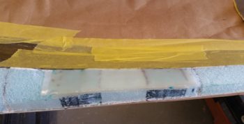
I then laid up my prepregged 2 plies of BID over the hard points, and then peel plied that since the final interior canopy frame layup will cover this glass.

I then taped off the back right half of the canopy along the “glass-to” line that matches the exterior glass line of the canopy.  I then sanded the bare canopy edge to give it texture to grip the interior glass when it’s laid up.

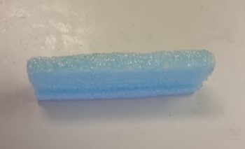
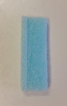
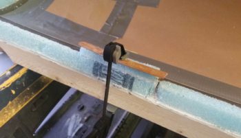
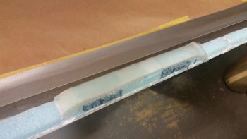
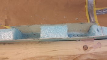
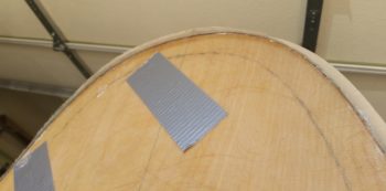
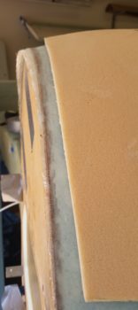
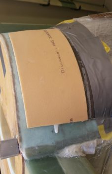
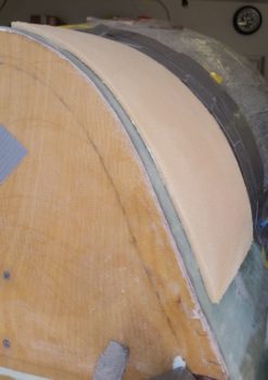
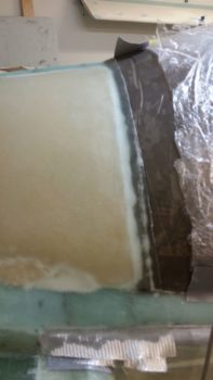
Since I don’t have 1.5″ of foam frame here, I manufactured it by shaping a piece of foam that will get micro’d to the existing foam rail.  I made it “L” shaped so that it also rests on the bottom half of the exposed canopy edge, with plenty of room for glass above it.

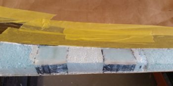
I then micro’d the additional foam piece in place that then gave me 1.5″ wide on the canopy rail right at the right side canopy aft hinge hard points.  The foam piece extends 1″ beyond the hardpoint segment forward & aft to allow for a transition back to the existing narrower canopy frame.

I then made up another piece, only for one hardpoint, on the other side for the #3 of 4 canopy latch.

[NOTE:  I’m going with 4 canopy latches.  Here’s why:  My canopy goes much further aft than plans, plus I have a longer aft canopy frame.  In addition to that little factoid, I don’t have a good option for keeping/incorporating the middle latch in the same place due to my roll bar frame.  If I move the middle latch forward 2″ than I can just barely clear the frame, but since I have the entire kit from Jack Wilhemson, pre-made, then I only have enough of the long rod (tube) that then forces me to move the aft latch forward about the same as the middle latch.  So, I have much more canopy + frame aft, but then I’d be moving my aft latch forward a minimum of 2″.  I don’t much care to do that.  I’d rather move the aft latch back an inch, move my middle latch forward 2″ and then fill that gap in with another latch.  With a MUCH bigger canopy than stock I think I wouldn’t mind having one more securing latch anyway!]

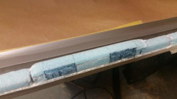
Here’s the foam piece micro’d in place for the #3 of 4 canopy latch, that will be located just aft of the roll bar frame.

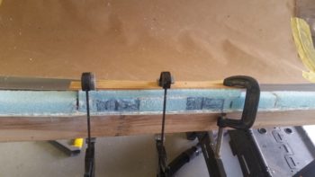
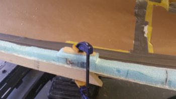
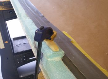
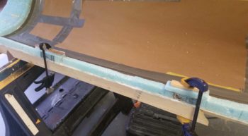
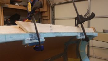
I then cut another piece of foam (quickly, since I had leftover micro) and clamped it in place on the left side aft canopy frame.  This foam piece will of course make up the left aft canopy latch hardpoint.

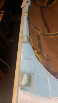
So, here are the foam pieces (incorrect width! more on that below…) for the aft 2 canopy latches, secured in place with clamps while the micro cures.

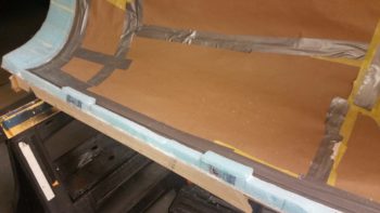
And a bit a later after the micro cured…. look nice eh?  But again, wrong width!

My mindset the whole day had been geared towards the aft hinge hardpoint, which, no matter what size the longeron is needs to be 1.5″ minimum width to have a good foundation for mounting the hinges to.

With that in mind, I got busy shaping/curving the top side of the added foam so it made a nice transition into the canopy edge.

I prepped it in the same fashion as the front hinge hard points and as I was finishing up the 3 ply BID layup I was thinking about my next task: glassing the 2 hardpoint retaining layups on the other side…. I then had a DOH! moment.

As I mentioned, no matter what size the longerons are, the 1.5″ wide hardpoint works fine for the hinge hard points, but that is not the case with the canopy latch hard points, which MUST overhang the longeron inboard since the latch assemblies attach inboard of the longeron.  Remember, from the pilot’s seat aft my longerons are a hair over 1″ wide, so a 1.5″ wide hardpoint works for a 0.7″ wide longeron, but not a 1″ wide longeron.  Ugh!  The good news is that I caught my error before I glassed in the retaining layups at these hard points.

Again, having some left over micro, I quickly made up 2 more additions to bring the canopy frame inboard a minimum of 0.35″ to allow enough hardpoint for the latch assembly to attach to.  The foam pieces are a bit thicker than required, but of course I’ll just sand them down to the proper thickness before glassing the retaining layups.

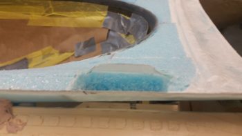
I then got busy digging out the foam and removing the inboard peel ply off the 3 left side forward hardpoints . . .

And the two forward right side hinge hard points.

BTW, although these layups were fairly fresh and I used NO micro on the foam surface where I applied the peel ply, it was still amazingly difficult to remove…. each hardpoint took a good 10 minutes in just removing the peel ply!

About this time in the evening is when everything turned magical, and by magical, I mean it went south ….. a bit.  Kinda weird and still assessing!

I started off by rereading the plans and then proceeded to glass in the 3 hard points along the front left side canopy frame.  I knew from accounts from other builders that 15 plies in these hard points, especially the deeper ones I had, was simply a fantasy and that it required a whole lot more than that.  I gathered up all my BID scraps, whipped up some flox using my “slow” hardener (75/25 slow/fast) to a point where it was right at the cusp of being wet flox (i.e. towards the thicker side of wet flox), and got to work.

Ok, first off, my bad for not taking into account the heat in my shop.  It was HOT outside and well over 80° F in my shop.  Secondly, I had never encountered an issue with a large scale exotherm type event with anything other than using fast hardener.  IIRC, in Germany I had an exotherm with a huge cup of epoxy when I left it sitting there for a good while when I was doing something really big like the wings or fuselage, and one event when I used fast hardener for the filling in the one of the elevator hinges . . . which resulted in it spitting the flox right out of the hole.

But just as I was a few plies from finishing up these holes, I started to see some bubbling around the edges of each hole.  I felt the sides of the retaining glass and it was hot, so I grabbed my thermometer.  I got one reading at 201° F for a blip, but couldn’t replicate it. Most of the readings on all the surfaces on or around the hardpoint layups were in the range 160-195° F.

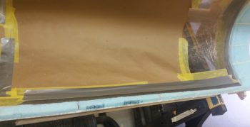
I had a couple of small leaks around the retaining glass layups going on which had annoyed me since I had to keep wiping up epoxy running down the inside of the canopy (one of the few times I’ve used paper vs plastic, and I got a fair bit of epoxy running down the paper!)…. however, I think these leak areas worked to allow the heat to vent and the layups to stay in place with no expulsion action going on.  I continued to monitor the temps as there was no discoloration of glass on the top side of the canopy frame and no melting foam anywhere.

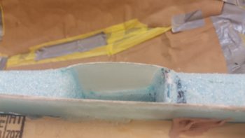
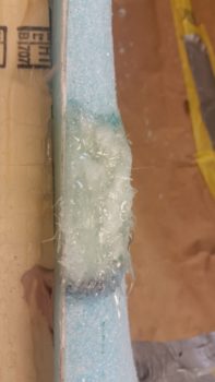
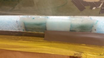
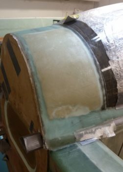
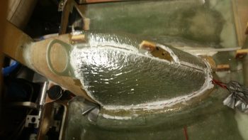
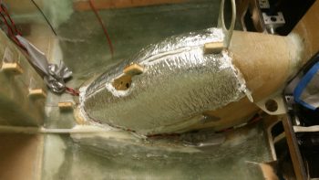
Out of curiosity I tried to add a bit of flox to the top side of each layup just to use it up and get the final 0.2″ of fill on each hole.  However, when the flox hit the bubbling brew on each hole it just burned out immediately and turned white (as you can see in the pics below).

The layups stayed warm for quite a while, but again, except for one non-repeatable blip just over 200°, I never saw any dangerous temps.  I’ll cut a core out of one of the hard points to see if it is solid [it should be, it was filled with glass] and check to see if the epoxy/flox just cured overly fast or if it burned out.

Having learned my lesson, I then grabbed a can of straight SLOW hardener and got to work on the right front hinge hard points.  Note the duct tape on the front hardpoint… this tape plays a key role in the next part of my story.

You see, as I was filling up the 2 front hinge hard points, I thought to myself the front hard point must be bigger than the back one, because the back one is filling up noticeably quicker with the same amount of flox and glass going in.  That’s when I realized the front hardpoint was leaking and thus harder to maintain the same level as the aft hardpoint.

Seeing that I wasn’t going to win this game, and almost out of flox in my cup, I simply cut a piece of peel ply for each hole and set the peel ply in place.  I would simple finish these holes with flox paste tomorrow and call it a day.  I did a final wipe down of all the epoxy that had run down into the canopy onto my thick brown paper, and knew I’d be back one more time for some cleaning before heading to bed.  And with that, I went upstairs and took a shower.


When I returned to clean up the epoxy mess caused by the leaking front hardpoint, what did I find?!  These hardpoint layups –with straight SLOW hardener– both had some minor bubbling going on around the edges!  I grabbed the IR thermometer again and checked temps (again!) and sure enough, same range as the left side: 160-195° F.  Highest temp I saw on this side was 198° . . .  amazing.  Again, no discolored or burned glass or foam anywhere, just a really hot curing layup. (sorry, no pic of this tonight but I’ll grab one for tomorrow’s post).

So, I cleaned up the epoxy, went upstairs to spend some time uploading the pics for this post and returned about 45 minutes later.  The temps were still fairly high, although significantly cooler (130-150° F), and the epoxy leak had stopped, so I did a final cleanup of the epoxy and pulled out the wet tape and paper from inside the canopy to ensure I had no curing flox or epoxy on the inside canopy surface…. thankfully it was really clean and nothing had really gotten onto the canopy.

Since the weather temps are high here and my canopy hard points are significantly deep, for the last 4 hard points I will fill them halfway and then peel ply the layup, and then finish it after it cures.  All I can say is wow.  I guess my technique of trying to follow the plans is more hazardous than stuffing the holes with BID and pouring wet flox in & around it!

All part of the struggle I guess of building these airplanes!


Chapter 13/21 – Turtleback tweak

First off, I know I’m spending a number hours more per day than I had planned on this canopy… however, I both want to clean up what I consider a big SNAFU on my turtleback and get the canopy acceptably configured for transport.

Defining the turtleback issue:

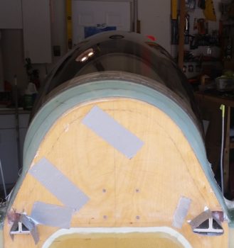
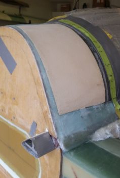
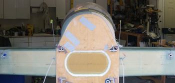
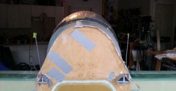
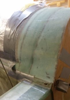
In the pic below, note the 9 O’Clock bulge and the 1-2 O’clock deflation.  I think I unknowingly did this by forcing the canopy bottom corners both over to the right before placing the turtleback foam in place.  Actually, I did notice it, but I thought it was a very slight, minute shape shift. It just wasn’t obvious nor clear that it would become so obvious and prominent after shaping and glassing the turtleback.

I wanted you to see the pic below, with the turtleback unmarked and in its current “natural” state.

The turtleback shape mitigation plan:

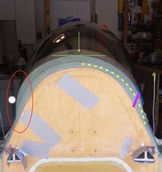
Here is my analysis of how to minimize the misshapen turtleback, and as you can see in the pic below I’ve marked it up to explain my mitigation plan.

First off, let me reiterate and be clear that my plan is to MITIGATE this off-balanced issue as best possible.  I have NO illusions of completely eliminating it.  The only true fix would be to rip off the canopy and redo the whole thing, with my entire focus then being how to mitigate this configuration debacle on the aft end vs (again) eliminating it.  And of course risking the chance of screwing up the very nice outcome of the front 90% of the canopy!
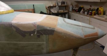
Problem #1 is the bulge on the left side, denoted in the pic below with the red oval and the white star being the apex of the bulge.  Note how below the star the canopy is vertical to almost coming back inboard.  Contrast this with the other side (right) where it has a comparatively gentle sloping curve, much more constant in nature.  To be clear, the aft canopy edge drove the shape of the turtleback so the only thing further outboard than that canopy bulge on the right is the 3 plies of BID holding it in place.

The REASON this shapeshifting occurred was most likely my maniacal –and probably misplaced/misguided– adherence to keeping the center canopy elevation even with the upper engine cowling extended contour angle (denoted by the green arrow and line).  If I had adjusted the canopy and let the elevation of the top go where it wanted to naturally, I think I’d still be dealing with this configuration oddity, but just in a less severe form.

Yet another issue, that will actually help in the attempted remedy of this SNAFU, is that for some mysterious reason –despite many repeated measurements– the fore/aft vertical canopy line of the turtleback glass overlaying the aft edge of the canopy is 0.35″ aft on the right side than it is on the left… which I’ve denoted with the blue line.  This obviously means the left is more pronounced when looking at the turtleback from CL aft as in this pic because its termination line is 0.35″ forward than the right side.  Making the bulge even more pronounced!
My plan is a 2 step plan.  First is to fill in the area marked by the yellow dashed line with 1/4″ foam and shape it.  Focusing on trying to manufacture a right side apex (purple line) opposite the left one.  I will also very aggressively sand the left side along the apex line to knock that down as much as possible.  Even 0.020″ will make a difference.

Part of the deflation between the 12 O’clock and 3 O’Clock positions is that on the left side my sanded depression for the 3″ UNI tape was close to spot on and it was even with the other foam surface, whereas on the right I went just a hair deeper and the UNI tape is not proud nor even, and is ever so slightly sunken… but not enough to affect the glass transition with the overlying BID.  It just adds to the depressed/flat/deflated look on that right side.

Now, I say a 2 step plan due to the fact that I feel I can/should deal with the turtleback to canopy angle issue later, after I get the upper cowling in place.  However, IMO I need to see if this remedy for the right side will work effectively BEFORE I pull the canopy off to shape and glass the interior surfaces.  If it just doesn’t work, I may go further in my corrective actions.

One final thought on the remedy to my unsightly creation, which actually isn’t really a remedy but rather of byproduct of the shape and configuration of my plane’s major components.  The bulkiness, size and shape of the canopy does a good job of hiding this issue from the front.  It will most likely be more noticeable with the airplane in the grazing position because it naturally takes more of the canopy’s sheer size –that serves to block the turtleback from view– out of play.  The other saving grace for my surreptitious cover up here is that the cylinder humps on each side of the upper cowling serve to block the view of the lower half/third of each turtleback side when viewing it from the back side of the plane (determined by my holding the cowling in place and assessing the aft view with cowling in place).

Clearly what I’ve shown here in these 2 pics is NOT visible (to my knowledge) in any of the pics I’ve taken at other angles.  Since you can’t be on separate sides of the airplane at the same time, I think if I add mass to the right side and mitigate the off balance between the two sides it would be really hard to get a really good view of this abomination at any other angle other than straight forward or aft of the plane.

Finally, I’m not trying to hide bad workmanship and be done with it.  Clearly there are no structural issues at play here and it’s my belief that any airflow imbalance will be minimal.  But for the sake of getting this thing in the air, and also to not waste any more time, materials, or money, I want the best mitigation possible and point out the view-blocking components as a point of note.  No builder wants a glaring, non-structural issue being the focal point that eyes are drawn to on their creation as it sits on the ramp!

So I started today by trimming the overhanging cured glass from around the firewall.

Here’s a side shot of the overhanging glass over the firewall’s aft edge.

Here we have the glass trimmed away that was hanging over the firewall and also the 1/4″ thick Divinycell foam that I micro’d to the right side turtleback.

I then did an initial round of sanding on the added foam, as well as cleaned up some micro runs.

Here’s the 1/4″ thick added foam piece sanded and shaped down close to its final shape before glassing.

Here you can see that, although still not perfect, the addition of the foam has taken the shape & aft view of the turtleback from “Ooh, gross!” to “Hmm, it’s not horrible…”

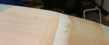
I then micro’d the foam and glassed it with 2 plies of BID.  I used an extra ply to allow me to really hit it hard with a sanding block if need be when it comes time to finish the surface for paint… with the micro finish allowing me to further fine tune the turtleback’s shape and symmetry as well.

Here’s a shot of the shaped & glassed foam added to the right side of the turtleback

This pic shows the newly positioned line of the canopy to turtleback intersection.

Before I got busy sanding and shaping the added turtleback foam, I Fein saw cut the aft edges of the canopy at the longerons.  Here’s the left side, but I forgot to grab a shot of it on the right side before I reglassed the added foam piece.

I also took a few minutes to dig out the foam in the mouse holes on one of the 3 strake ribs that I left out of the last haul to NC.  I’ll try to knock these out as I go about my other build tasks so they’re ready when it comes time to build the strakes in the next 2-3 months.

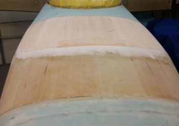
I also took a little bit of time to take the long sanding board and really finalize the shape of both the flocro transition for the added Balsa wood strips on the aft nose cover, as well as the intersection of the “old” nose sidewalls and the new foam I just recently added to make up the forward nose sidewalls.

[I have some slight “shoulders” on the nose sides right where I added in the new PVC foam when creating the top nose structure.  I sanded these for a bit but I think I have to accept the fact that since I left my original nose sidewalls a bit high and with a vertical surface, that the nose then somewhat sharply transitions into the top curve… this makes for a somewhat abrupt change at the nose sides from curved (top) to vertical (side).  So although curved, it’s not as smooth as I would want.  A minor issue, as I think it has zero affect on nose structure strength or aerodynamics, and I suspect not highly noticeable when the nose is finished to paint.]

Here are some closer up shots of the flocro transitions between the edge of the added Balsa wood and the front/side areas of the aft nose cover.  To be clear, the height of the front edge of the balsa wood was about 1/32″ when I applied this flocro, so there is not a ton of added flocro added here.

Tomorrow I plan on actually cutting the turtleback to separate the aft canopy frame and then remove the canopy from the fuselage to begin canopy internal shaping & glassing.


Chapter 18 – Canopy front skirt

I’m dealing with a repair issue on my truck that took up a number of hours both yesterday and today, so I didn’t get as much shop work in as I would have liked on the canopy today.  I did get a few hours in though.

I started by cutting the glare shield’s aft edge trim/seal to length.  I also tapered the ends so that it flows in nicely at the outboard edges.

[Note the very outboard edge of the glare shield that is situated immediately over the longeron, this is discussed below].

Here’s a shot of the right side cut/tapered aft edge trim/seal of the glare shield.

I then covered the trim/seal with painters tape to protect it from getting gummed up by the duct tape.

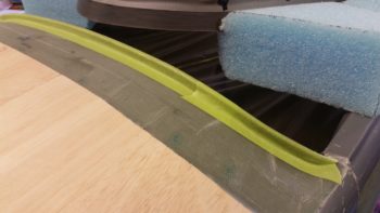
I then applied a couple layers of protective duct tape over the glare shield.  After I got the tape on I realized I hadn’t (re)trimmed the very outboard edges of the aft nose cover, along side the glare shield.  These ends are immediately over the longerons and for the canopy frame to be shaped properly they needed to be trimmed in width . . . or at least very close to their final width.

So I peeled back the tape on each side and, using the Fein saw, trimmed off about 0.1″ of the very outboard edge of the glare shield in between the taped in 1/8″ aluminum spacer for the canopy and the aft outboard edge of the Balsa wood on the aft nose cover (no pics on this trimming).

I then laid the tape back down in place.

A side shot of the taped up glare shield…. with the aft edge trim/seal in place.

I then spent about 45 minutes measuring and shaping a block of foam for the center section of the canopy front skirt.  I’ll get a shot of that tomorrow with the plan being to finish up the canopy skirt/frame foam, and then get the canopy frame shaped and glassed.


Chapter 13/18/23 – Glare shield trim

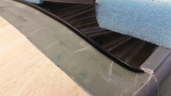
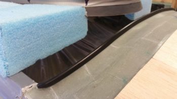
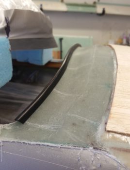
In prep for getting the canopy install much farther along than it currently is in order to haul the fuselage down to North Carolina, I measured, researched and then ordered some black trim for the aft vertical edge of the glare shield.  The trim will serve two purposes:

  1. Keep from slicing open body parts that come in contact with the rather sharp edge.
  2. Compress slightly into a groove on the bottom of the canopy skirt to guard against incoming rain and moisture, wicking it to the outer edges of the glare shield/canopy.

I ordered the trim from McMaster-Carr a few days ago and it came in today.  I have to say I’m quite pleased with both the fit and the look of the trim.

Here’s a bit closer look.  When the airplane is finished to paint, the current green area of the glare shield will be a flat black, whereas the Balsa wood area will be painted whatever color the nose and canopy frame is painted (haven’t decided yet . . .).

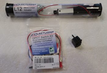
I also received yet another L12 micro-linear actuator that I’ll be using to manipulate louvers that will cover the oil cooler to adjust the airflow for optimized oil cooling temps: louvers closer to closed in the winter for less engine oil cooling and pretty much wide open during the hot summers, with stages in-between during the fall and spring.

The switch that I also bought from the Robot Shop is a latching type switch (analogous in function to a latching relay) that will allow a simple actuator to be stopped at discreet positions –versus just merely fully opened or fully closed– to allow for a myriad of settings to dial in the oil cooler to temp during flight ops versus having to mess around with making, sizing and attaching oil cover plates on the ground.

As a point of note, I got the louver idea from Marc Zeitlin who incorporated this simple mod on his Cozy IV with great results.  The main difference in my configuration vs Marc’s is that Marc incorporated a cable to manipulate the louvers whereas I will be using a significantly lighter micro-linear actuator.

I’ve been painting the house all week with the phenomenal help of Stacey from North Carolina.  It’s been a very productive week but I am quite tired, so after taking just a bit to recharge I’ll be back on the canopy build for the next 2-3 days (interspersed with some house prepping tasks of course).


Chapter 13/22 – Keepin’ NB warm!

Or rather my legs actually…. !

Shortly after I got back from NC I tweaked my back a little, so yesterday, still a bit tired from the haul down to NC, I was taking it a little EZ and unintentionally ended up making the whole day a research day … I did some personal stuff and spent a lot of time on the computer researching build stuff, including a nascent plan for how I’m going to knock out the significant number of metal projects I have coming up for various parts of the build . . . throttle handle lever, starter contactor mount, canopy lever are the big ones off the top of my head.

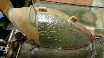
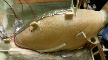
Today I got busy on one of my tasks that I am charged to do under the auspices of the 3 DAY BLITZ, Round 2: insulating the Nose Wheel Cover (NB).  After thinking about it a bit I decided to insulate NB in 2 phases, the front 2/3rds section and then the remaining 1/3 aft section.  By doing it this way, it allows for more glass-to-glass contact and secures the insulating material better in place… IMHO.

I also split the 2 sides so to create a narrow trough down the center which would be a low-point depression in the insulation to ensure clearance for the bottom edge of the Triparagon when it’s mounted in place.  Again, it would also provide a glass-to-glass securing point down the centerline of the insulation.

After giving the NB and surrounding fuselage floor a thorough sanding, I started by cutting to shape and then using Silicone RTV to secure the insulation to the right front 2/3rds of NB.  Remember, I’m cheap . . . and if you want to be read in on a little secret: this insulation is the flooring material underlayment I bought in Germany to use as a hot-tent for post curing the fuselage back in 2012!  Ha!

You can see that although this insulation is somewhat thin, it still has an edge on it.

I then cut to shape and RTV’d the left front 2/3rds insulation in place on NB.  You can see I used the attached nylaflow –that runs partway up NB at an angle for the parking brake cable– as the demarc point for ending the first round of insulation, with the underside getting insulted in phase 2.

Here’s another shot of NB’s front 2/3rds area insulated and ready for a 1-ply BID glass covering.

I then whipped up some epoxy (with fast hardener) and micro’d the edges of the insulation and the intersecting corners of NB and the fuselage floor, where the respective pair of charger wires run along each side.

I then laid up one solid ply of BID across the entire front 2/3rds area of NB covering the insulating material I had just RTV’d in place a bit earlier.  To keep the glass in the narrow center trough between the 2 pieces of insulation in contact with NB for a good glass-to-glass bond, and as deep as possible for clearance with the Triparagon, I took a length of plastic tubing (that was used for the gear leg conduits) and pressed it down over the peel plied center trough.  To keep the plastic tubing in place I of course had to come up with some clamping contortions to do so.

I also peel plied the glass-to-glass bonded patch where the 3 holes are for the OAT probes. I then filled an ACS baggy with sand, taped it up and set in place on the glass-to-glass bonded patch to compress the glass down and ensure the best possible bonding.  I leaned the 90° drill on it to keep the mini sandbag in place and add as much reasonable weight as possible.

I then spent a number of hours on the phone with fellow Long-EZ builder Brian Ashton from Alaska, and after sharing our war stories and build progress, I then went downstairs to the shop and pulled the peel ply and cleaned up the layup.

I didn’t see any issues whatsoever with the layup and am extremely pleased with how the first phase of my NB insulating came out.  As for the respective set of charging wires, I’m typically NOT a fan of burying wires under glass or micro, but here the runs are so short that if I did have a problem I could use the Fein saw to dig them out.  I oversized the wires simply to avoid any potential problems and to handle any added heat (negligible IMO) by being encased for about a foot in a ply of glass and some micro, so I really don’t foresee any issues.

Tomorrow I plan on finishing up insulating the NB cover and then press on with other internal nose & avionics bay tasks that need completing before the top of the nose gets constructed.


Chapter 22 – USB charger Dude!

Today was a bit heavy on research and planning… which I grabbed breakfast down the street and did a fair bit of that there.

At the risk of sounding like I’m obsessively repeating myself, my attempt over the next few days is to knock out some of the smaller tasks that are just that: smaller tasks now, much more difficult tasks later.  It may seem like I’m nibbling around the edges of the pie vs just jumping in and scarfing down the good stuff in the center (it does quite often to me!!) but I think –again– knocking out the small, easy stuff while it’s small, easy and ACCESSIBLE is a much better way to go in the long run.

Case in point is the USB charger bracket that is the twin of the left side nose wheel cover cigarette lighter charger.  My front seat USB charger will be located at the intersection of the nose wheel cover (NB) and the lower instrument panel’s center strut, on the right side… about as close the gear viewing window as you can get.  As I see it, this is otherwise dead space so a good corner spot to stuff something into.  And back to my original point, I can’t imagine trying to construct this somewhat innocuous little bracket in place with the top nose panels constructed.

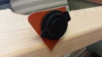
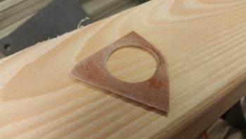
I spent well over 2 hours on this USB bracket today, starting off with a good 45 minutes of trial and error measuring, test fits, mockups and tweaking to get the final USB charger’s bracket –which is a tad bit bigger than the cigarette lighter charger’s bracket– cut and drilled to the right shape and dimensions.  As you can see, the USB charger bracket was cut out of my 1/16″ phenolic stock.

I then sanded down the 1/16″ USB charger bracket to prep its surfaces for glass.

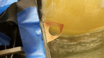
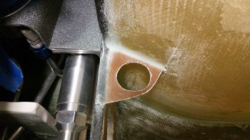
I then 5 min glued it in its place at the aft corner intersection of NB and the lower instrument panel cross piece.

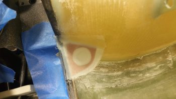
I then prepregged and laid up 2-plies of glass top (I used scrap glass, so 1 ply BID over 1 ply UNI) and 1 ply of BID on the bottom side.  I used small flocro fillets for the corners, heavier on the flox.  I then peel plied the top side layup.

I then went out to dinner with my buddy Rob for a couple of hours while the glass cured. When I returned I pulled the peel ply, knife trimmed the layup and then sanded the rough edges to clean it up.

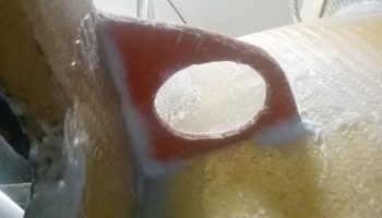
Here’s a shot of the lower layup… this is the first I’ve had eyes on this bottom layup since I did it all by feel the when I laid it up initially.  I intentionally drove the fillet away from the spot where the mounting hole is closest to the NB side to allow room for the large plastic mounting nut that secures the USB charger in place.  Of course viewing this pic did identify one more spot that I needed to knife trim.

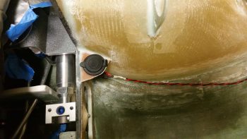
And Voila!  Here’s a test fit of the USB charger . . . fits like a champ!

I don’t have any pics this time around of the next 2 items, but I spent well over an hour taping up one of the plastic aviation oil bottles I saved to create an oil storage box that will secure a quart of oil in the nose.  With oil being a bit heavy I figure why store it in the spar or headrest when I can eek out a spot for it towards the very front of the plane.  Plus, with a storage box with a securing lid just big enough to slide a quart bottle of oil into, I can also stuff a rag in there for use as well.  This may be round 1 since it might not come out as nice as I had hoped…. we’ll see (literally since I’ll make sure I grab some pics tomorrow).

I also spent a good hour doing the initial clean up with a straight razor blade on the myriad of runs I had when I clear coated the NG30 cover.  I swear it looked like the first time I had spray painted ANYTHING and had zero understanding of the whole concept of spray painting something!! IIRC it was outside at night so my pushing to get it done then just caused a bit more work for me now!

So with the USB charger bracket mounted in place, I can now press forward with my plan to insulate the nose wheel cover and secure it in place with a ply of BID.  I’ll also continue with my 3-DAY BLITZ to work all things internal to the nose and avionics bay before closing up the nose.


Chapter 23 – Engine Pickling… MC

“MC” for those of you never having filed a travel voucher for an Air Force mission was always the last 2-digit code annotated and stands for “Mission Complete” . . . which is currently the status of my engine pickling endeavor.

I will note that with the big task of welding up the engine stand mounting brackets and seeing my buddy Greg off over a couple of nights really put a dent in my schedule, and put me way behind the power curve time-wise.  Since I had a locked in rental on a moving trailer, and a locked in timeframe that I needed to be in NC, my back was somewhat against the wall.  Still, the primary goal here for me was to get this engine pickled, and then move what I could in the allotted time I had left.  I just was not going to risk any internal engine corrosion with any more time than was necessary.  In short, it was time to get this engine pickled.

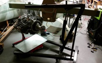
With having removed the engine last night from the fuselage, I then did the limited trial and error dance for getting the bottom engine stand mounting bracket mounted to the engine mount.

However, the top mounting bracket was the big dance, and it took a couple of hours to dial that baby in.  The primary issue was that I forgot how the engine mount stubs –and thus the engine mount extrusions– are at a slight angle to follow the fuselage angle (this is denoted in the plans).

After much wailing & gnashing of teeth, a number of expletives and my new boneyard of broken drill bits (I think one side of the mount ended up so hot that it was in an annealed type state… since drilling a hole into it was like going through stainless steel) I finally got it all put together and then the engine mounted to the stand!

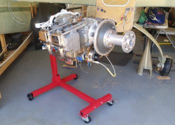
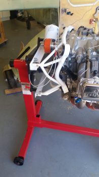
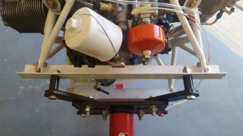
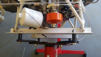
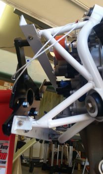
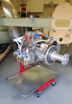
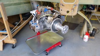
Here’s a better view of the engine mount attached to the engine stand mounting brackets.

And a couple of views from the top.

Ah, yes, and of course here we have a view more from the lower side.

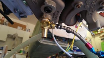
I also drilled a hole through the lip of the oil drain valve to accept a 0.041″ piece of safety wire.  I then threaded the oil drain valve in place.  Unfortunately I was remiss in remembering that this was a Japanese made oil drain valve, and thus metric, so my 3/4″ wrench was just a hair loose on it.  When I really went to snug it up that last little bit I rounded a couple of the wrench flat corners over.  I then grabbed a 19mm wrench to finish up the last little bit of snugging it up tight.

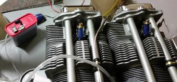
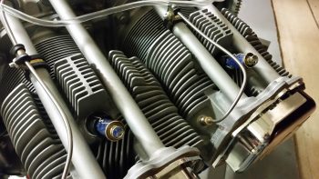
I removed the spark plug cylinder dehydrators from the bottom side of each cylinder and replaced them with standard aircraft spark plugs.  I then removed the top spark plugs while I squirted preservation oil into each cylinder, and then replaced them with standard aircraft spark plugs as well.

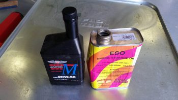
I sprayed approximately 2 oz of PolyFiber Engine Storage Oil (ESO) into each cylinder when its piston was in the down (inboard) position.  I will admit that I realized as I was prepping for the pickling of the engine that an optimum solution would have been to have cover plates for both the intake and exhaust manifold ports, but I didn’t have either, and again, since I was in a time crunch I pressed forward and simply placed an oil drip pan underneath the engine for any runoff.

I will say that I shown a pen light into each cylinder with the top plug out, and what I saw on the each cylinder wall gave me a huge sense of relief.  I could see the honing of each cylinder wall with bright shiny metal and NO corrosion…. which I’m very thankful for.

I then poured 3 quarts of Phillips 66 20W-50 oil into the engine, fed in the remainder of the ESO and then poured in an unused quart of Harley-Davidson 20W-50 to top it off.

With my 4+ quarts of oil in the sump, I then flipped the engine upside down and let it sit that way for a good 5+ hours as I loaded up my rented moving trailer.  My goal here of course was to bath the top-mounted camshaft in a bunch of oil.

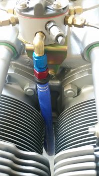
In my haste I failed to cap the oil heat return fitting so it spit out a bit of oil when I flipped the engine upside down.  Beyond that little issue the engine stand seemed to work exactly as I thought it would in allowing me to wrench on the engine and also rotate it as if it were on an “engine spit.”

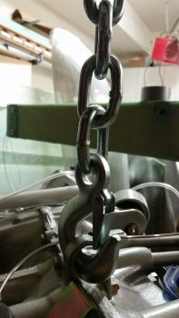
Before I left for NC I turned the engine back right side up and attached the hook of the engine hoist to the top engine lifting tab.  I’ll turn the engine back upside down when I return from NC, but since I just welded up the engine stand mounting brackets I didn’t want to test my luck (just in case).

I did leave a bit of a gap between the engine hoist hook and the engine lift tab to allow me to quickly identify if any of the welds on the engine stand mounting brackets gave way while I was gone…. again, just a precaution with an expensive aircraft component.

For the final push on the engine pickling, as I was working on the engine I was also concurrently baking up another batch of pink desiccant.  Once it had turned blue and cooled, I then recharged all the cylinder dehydrators and the main engine dehydrator bin.  I then removed the top spark plugs and replaced them with the spark plug cylinder dehydrators.  Note that now the spark plugs are mounted on the bottom of each cylinder with the spark plug cylinder dehydrators on the top.

Again, I’ll be gone for a few days, and with the engine now off the fuselage and pickled for the time being, when I return I’ll be putting all my energies into building the nose and canopy to finish off the aircraft centerline build.


Chapter 23 – Engine Stand Brackets

I’ll start by apologizing again for my POS phone camera…. it annoys me that apparently the only thing it’s good for is selfies.  But it’s all I have right now, so please bear with me as I bear with posting these crappy pics (that I often take 2-4 shots of and all are still slightly out of focus…. and yes, I’ve checked the settings many times!)

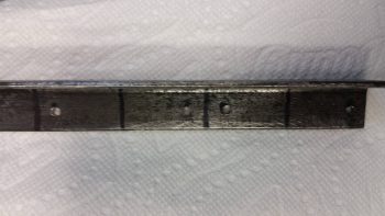
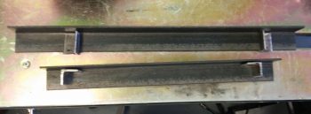
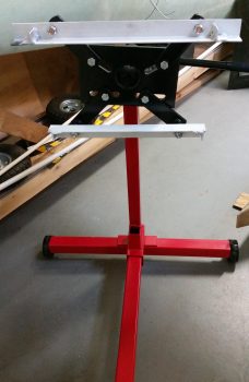
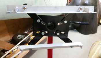
I started with a 1″ x 1″ angled steel bar that I had on hand.  It had some surface rust but I was able to remove the majority of it.  I then marked 4 x 1.5″ tabs on one end, drilled holes that would allow for a welded “hardpoint” between the flat intersecting pieces of metal being welded together, and cut the 4 x 1.5″ mounting tabs from the angled steel extrusion.

I then set the mounting tabs on the associated 1.5″ x 1.5″ angled steel main engine stand bracket cross pieces –top & bottom– to ensure I had them set in the right places.

Now, as I mentioned during my TIG welding setup it’s been a couple of years since I’ve welded, but with both the high expense of Argon gas and my limited time I jumped right in. I knew there was Argon in the bottle, but it was low enough it wasn’t really registering well. In addition, the nifty little cheat sheet weld chart that Lincoln gives out during the EAA Tig Welding Workshop called for a 3/32″ Tungsten electrode for 1/8″ steel. I only had 1/16″ on hand.

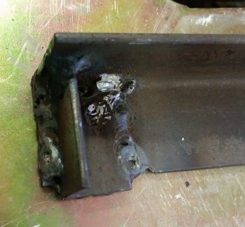
Nonetheless, I trudged forward and laid down some appropriately crappy welds my first go at it.  Towards the end of it I could tell I was definitely out of Argon gas, so with about 45 min left before the Gas shop closed I threw my empty tank in the truck and went on my quest to collect a fresh UBER EXPENSIVE ($90!!!) tank of Argon. [As a point of note, I ground and re-welded any of my initial welds that looked lacking in the strength department… with my limited time available, ugly welds here were acceptable as long as they were strong!]

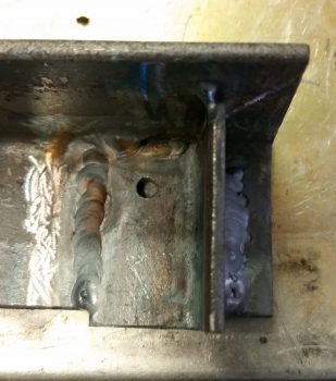
Upon returning back to the shop with a fresh full tank of Argon and some 3/32″ electrodes, this was what the other side welds looked like.  Just a tad better I’d say… (yes, still not up to par with the gorgeous TIG welds we see on YouTube, but again, strength was what I was after here, not necessarily beautiful welds!).

With the lower engine stand mounting bracket complete, I then started on the top bracket. Once I was finished with the top bracket, I spray painted both engine stand mounting brackets with the same fast drying white paint that I used on the engine mount.

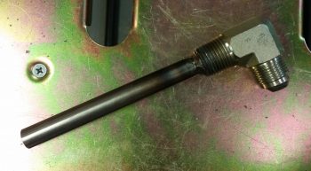
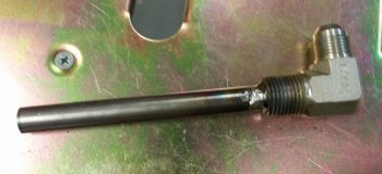
While the paint dried on engine stand mounting brackets, I then welded the 0.035″ walled 1/2″ 4031 steel tube inside the 1/2″ NPT x -8 AN oil heat 90° fitting.  It took me a bit to rig it up so I had good access and a good welding angle, and I have to say I was going along beautifully for the first 75% of the circumference of the weld.  I had to reposition the setup and I had only one little bit to go on the final weld when I slightly dipped the electrode into the puddle. Well, with so little to go I trudged forward to finish it.  Mistake.

Within about 2 seconds of dipping the electrode into the puddle –with my trying to concentrate on the thicker fitting’s base metal (I tend to go high on internal corner welds)– I blew about a centimeter diameter hole in the thinner walled tubing.  Since I had to buy a foot of this stuff, I ended up simply cutting a patch out for the hole from the other end of the tube.  I then prepped the patch piece and the hole area, and tacked it into place.

I ran some water through the tube to see if the patch worked, but I have a couple of leaking spots that I’ll need to do some touchup spot welds after I return from NC.  For now this is good, and I cut the 4130 tube at my calculated 4.4″ long (high actually).

I then ran out for a final going away dinner for buddy Greg since in reality this is the last time I’ll see him in quite a while.

When I returned, the quick dry paint had cured.  I then determined the best bolt hole locations for my configuration and drilled out the 1/2″ holes that allowed me to bolt the respective engine stand mounting brackets to the beefy engine mounting arms.

Here’s a closer shot.

With the engine mount ready to go, I then unmounted the engine from the fuselage.  I took this pic because I would often bump the engine and the starter bolt that I had setting in this location would fall off onto the shop floor.  However, it stayed right in its spot the whole time I removed the engine from the fuselage, so the operation must have gone fairly smoothly . . . both literally and figuratively.

Since I needed to make a decent amount of noise and do some grinding and drilling on the engine stand mounting brackets to get them mounted to the engine mount, I called it a night.


Chapter 23 – Tailored Sleeves

I started off today prepping some of the metal that I’ll use in constructing the mounting brackets that I’ll mount the engine & engine mount to on the engine stand (say that 3 times fast).  That didn’t last very long before I had to pack all the compressor hoses back in the shop to go to a Dr’s appointment that took a good 3 hour chunk out of my day.

From there I grabbed lunch and headed to my local Village hardware store for some 1/2″ nuts & bolts for the engine mount stand brackets.  My best bud Greg from my Air Force days, who I rarely get to see, stopped by shortly after I got home for a few beers in the shop as I gave him the rundown on my build progress.  Greg got a new job down in the Norfolk area and will no longer be in this area as of Friday.  Since I’m leaving Thursday for North Carolina for a few days, I wanted to carve out some time to spend with Greg to send him off.

As you can see, the way my day unfolded I didn’t get much done on the build.

I did remove the prop and get it packed back up and put away . . . without incident.

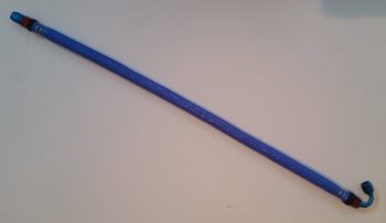
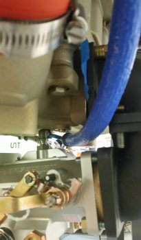
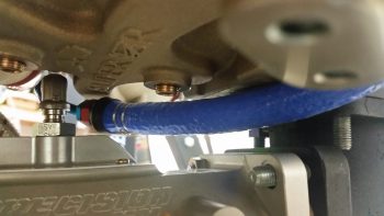
I then decided to get something done on the build, and since it was too late to do all the grinding and metal cutting that I needed to do for the engine stand mounting brackets, I pulled off the -4 stainless steel braided fuel hose that runs from the fuel injection servo that’s mounted on the bottom of the engine to the fuel injection fuel distribution spider on the top of the engine.  I then took it upstairs and fire sleeved it.

As most of you are (painfully) aware, my phone camera is just not that good at capturing pics, and since I just couldn’t get both ends of the entire hose in focus….

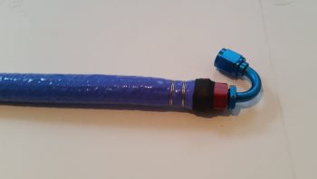
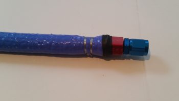
. . . I took separate pics of each end of the hose.

I have to say that the first couple of hoses I fire sleeved I used up the stainless steel wire that came in the package with the ClampTite tool.  Little did I know at the time that they included 0.041″ stainless steel wire with the tool, because when I used 0.032″ wire on this hose . . .  wow, it understandably went from quite the struggle to a fairly EZ endeavor wiring up the fire sleeve on this hose.  Yes, the ClampTite tool is infinitely more enjoyable to work with when using smaller gage wire!

After sealing the bare hose end edges with gray 3M fire barrier Silicone RTV and covering that application with a strip of black heat shrink, I then reinstalled the hose on the engine. So here we have the freshly fire sleeved -4 hose connected to the fuel distribution spider atop the engine.

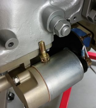
And here is the lower side of the fire sleeved -4 hose connected to the 90° outlet fitting on the top of the fuel injection servo.  Since I marred the Adel Clamp drilling its mounting hole out to 5/16″ diameter the last time, I’ll make up a fresh one it comes time to do the final install of the hose.

And one more shot of the newly fire sleeved fuel distribution outlet hose coming from the top of the fuel injection servo.

Tomorrow I’ll perform my welding tasks on the mounting brackets for the engine stand, get the engine off the fuselage and onto the stand, then appropriately pickle the engine.  After that I’ll roll solely into move mode to start packing up more of the house to get my stuff moved down to NC.


Chapter 23 – Clear Prop!

So today was PICTURE DAY! Remember getting all dressed up (or your parents mandating that you get all snazzed up) for school picture day?  Well, that’s what I did for the shop.  I started off by spending well over 2 hours doing some much-needed spring cleaning on the shop.

During my cleaning I took a few minutes to remove the ANL40 from the front side of the firewall in the hell hole and put it back upstairs and will install it later when I finish up the electrical components install in the nose.

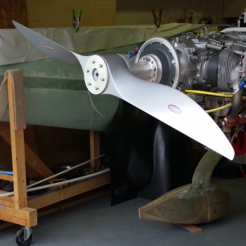
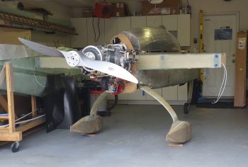
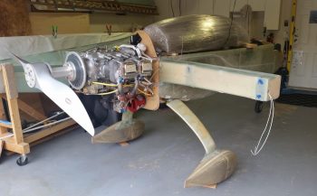
I then temp-mounted the propellor with the crush plate just for picture day. I was pleased with the how prop fit and looked mounted on the back end.

I took a slew of pics of course.  I ended up posting shots of the fuselage at different angles.  Believe me, I chucked a ton of pics out!  The main shot I was after was a straight shot from the aft end with the prop and wheel pants installed.

Here’s an angled aft view.

With these pics captured, my main goal is to weld up the angle-iron mounts that will allow the engine-on-mount to get mounted to the engine stand.

Although very close to the one above, I included this shot since it’s positioned a bit nose higher.

Another shot from a high angle.  In addition to the shots I took, my neighbor came over and set up all his photo shoot equipment and took a ton of pics with his high-end digital camera.   When I get those pics I’ll most likely post them here on my blog.

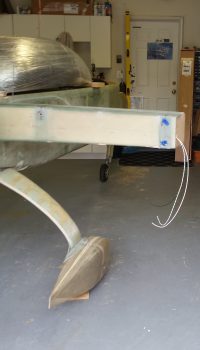
I’ll note that I’m very pleased with the how the wheel pants install turned out.

Here we have a shot of the installed right wheel pant with the canopy mocked up in place.

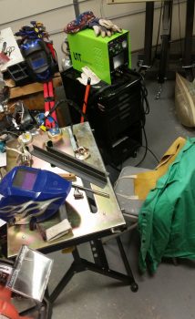
After the prop and fuselage pics were all taken, I then spent a good bit of time setting up my TIG welding kit for a good bit of welding that I need to do.  It’s been so long since I’ve welded with this box that at first I thought it was in-op.  Since this welder does stick welding as well, the ground connection on the front of the box is for stick welding, and the ground lead for TIG is actually labeled with a “+” sign…. which I finally figured out after spending a good amount of time tearing it apart and going through all the troubleshooting guides.

Tomorrow my focus will all be on welding, specifically the angle iron for the engine mount. In addition I’ll look to weld the oil heat standpipe tube to the 90° sump fitting and a tab on the aft right side of the roll over assembly to mount the canopy stay gas support.  Then my sights will quickly switch to getting the engine off the fuselage and onto the engine stand.

After I get all this welding done, and the engine on the engine stand, I’ll be transitioning into moving mode and to take a load of house stuff down to NC later this week.