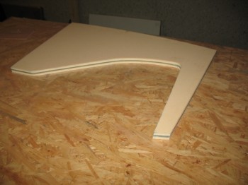
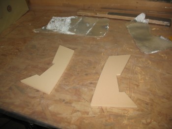
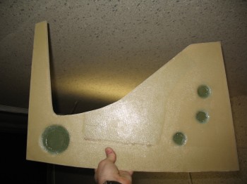
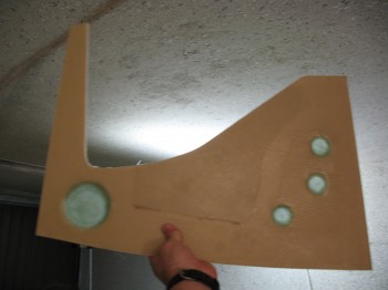
I’ve been figuring out & playing with some initial design changes on the lower winglet. I came up with this below. Although I won’t be using this design, I thought I would post a pic just to show some of the design processes I’m working through.

I’ve been figuring out & playing with some initial design changes on the lower winglet. I came up with this below. Although I won’t be using this design, I thought I would post a pic just to show some of the design processes I’m working through.
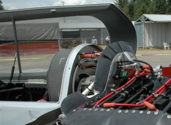
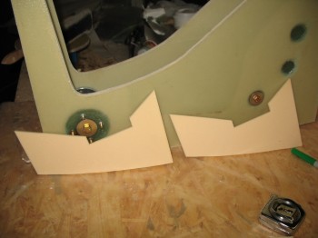
I had to run out & deliver some items I’ve sold online in prep for my move. Since it was in the latter part of the evening when I got started, I focused on planning out some details on what I call the “D-Deck,” the area at the aft end of the cabin, behind the GIB’s head, on top of the CS spar, and just forward of the firewall. Basically the rear passenger’s head rest area. I would like to build my canopy frame so that the frame continues past the aft edge of the canopy glass significantly farther than stock and have it intersect the firewall in much the same way as Wayne Blackler did on his Long-EZ:
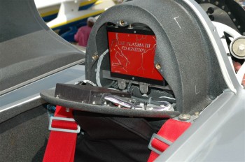
To me, this removes the cavernous area behind the GIB’s head, provides a headrest platform, and an area to hide away electronics (and the fuel tank vent manifold). Since I’ll be using GRT’s Engine Information System (GRT EIS-4000) I’d like to mount the EIS control unit in the D-Deck electronics area much like Nick Ugolini did (shown below, but without the spare battery) and as he discusses on his blog:
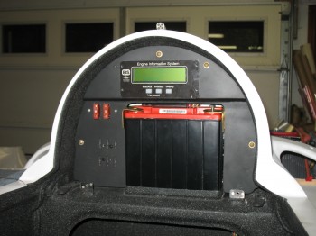
I’ll be honest, at first I didn’t like the thought of putting the EIS control head back in the aft of the aircraft. I didn’t really see the light until I spoke with a GRT rep at the Sebring LSA show and he asked me why I would want to mount it up front in a Long-EZ with all that engine probe wiring traversing a good total length of the fuselage (i.e. bad for space, current noise & WEIGHT). The GRT EIS control unit can really get away with one single wire feeding the EFIS all the engine info that is processed, tracked & displayed (which is a lot!). If one wants to be able to upgrade the EIS control unit (aft) at the front panel with a laptop connection, then they would only require a whole ‘nother whopping second wire (vs. Lord knows how many by bringing all the probes up to the instrument panel if the control unit was mounted there). Thus, I get a well deserved “DUH!” on that one. Ok, GRT (and Nick) ya’ got me this time, but never again . . . ha!
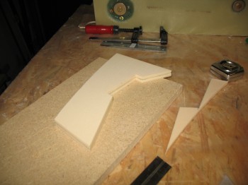
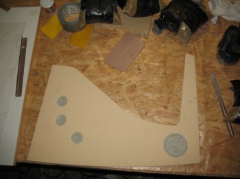
So I started measuring, designing and crafting my D-Deck electronics/fuel vent manifold mock housing out of poster board.
Also, although I’m not 100% one way or the other on whether I’ll have lower winglets installed on my bird (leaning more pro vs against), I would like an upgraded look compared to the traditional stock look. I don’t necessarily dislike or abhor the stock lower winglets (my buddy Marco growns even at the mention of them, and threatens constant Unfriending on Facebook if I install them . . . ha!). Anyway, I’ve started my research and am flirting with a redesign on my lower winglets.
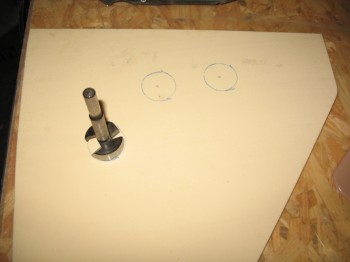
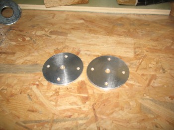
I didn’t do much today on the project either, but I did get my countersink in from Aircraft Spruce & immediately put it to work.
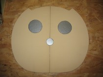
I countersunk the 8 each #12 screw holes in the NG8 aluminum plates.
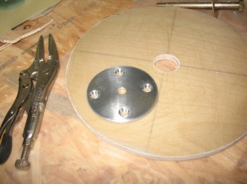
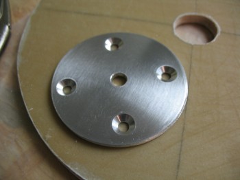
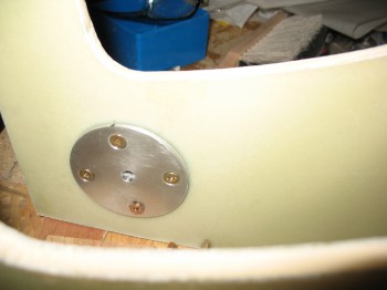
I then tried them out by mounting them to the NG30 plates.
I didn’t get a whole lot done actual build wise today. I researched more on the Davenport Pitch Trim system, and also figured out components needing ordered from Aircraft Spruce. Also tended to some paperwork duties as far as filing invoices, etc. All that and working & planning on my upcoming move.
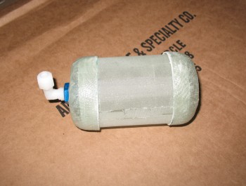
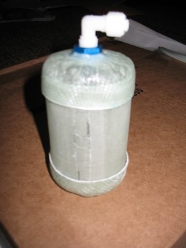
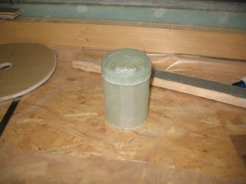
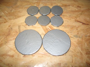
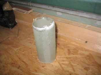
As for build actions, I pulled the fuel tank vent manifold end cap from its form, cut off the excess material & then sanded it. Below are the pics showing the manifold in its first ever appearance as one component.
Ok, so today I started working on Chapter 10 – Canard; Chapter 13 – Nose/Nose Gear; and Chapter 21 – Fuel system . . . due to an error in my glassing though, my Chapter 10 piece turned into a Chapter 22 – Electrical system piece . . . you’ll see below.
First, I’ll start with Chapter 13 where I removed the peel ply from the BC1 Battery Compartment struts (NG30 Extensions) & knife edged/sanded the edges.
Although I prepped some other layups first, for simplicity’s sake I’ll keep these all in order. I then glassed side B of each BC1 with a 2-ply BID layup & peel plied.
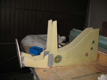
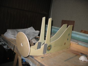
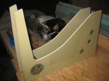
To jump ahead even further, here is the end result a few hours later after the BC1’s cured (I used fast hardener since the layups were small), the peel ply was pulled and the edges trimmed. I mocked up all the NG30 pieces–except for Napster, who was still in Time Out under the heater–to get an idea of how it all looked put together. Again, except for Napster, which gets mounted on the front of the NG30 vertical arms & aft of the BC1s, this below is the skeletal framework for the nose.
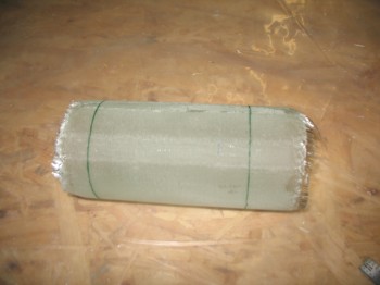
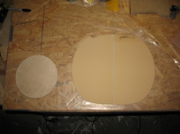
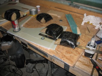
Now to Chapter 21 where I marked & cut the ragged ends off the fuel tank vent manifold body (that I glassed around a Rock Star energy drink can).
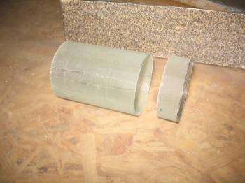
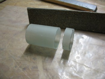
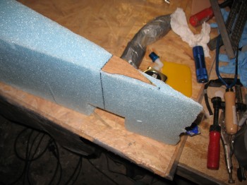
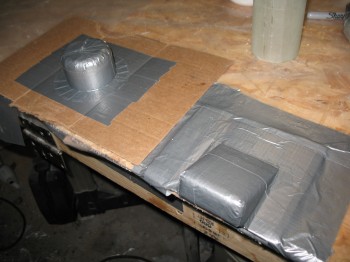
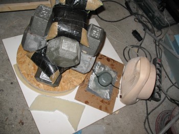
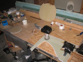
I then used one of the cut end pieces to make a form for the fuel vent manifold end cap using blue wing foam.
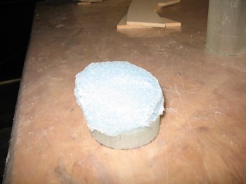
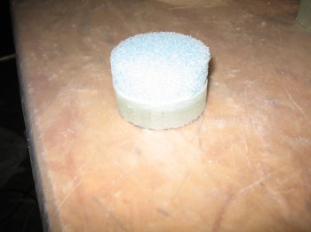
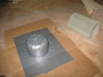
After I formed the shape I was looking for, I covered the entire form with duct tape & then fastened it using the tape to a duct tape base on a piece of cardboard.
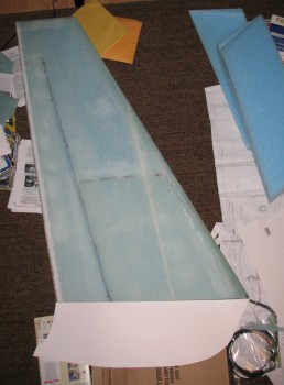
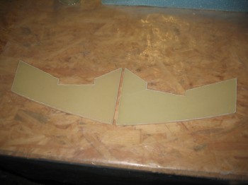
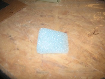
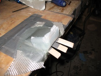
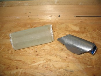
Now before I show any of the glassing on the fuel tank vent manifold, let me show what I was working on concurrent to this. I made a cardboard template of the shape of the canard next to the protruding antenna cables to make an antenna jack mount/cover for these cables, where they would tie into 2 respective jacks as a rather permanent fixture on the top aft/TE of the canard. I also shaped blue foam in an effort to make this jack mount/cover.
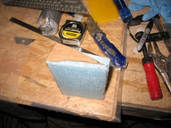
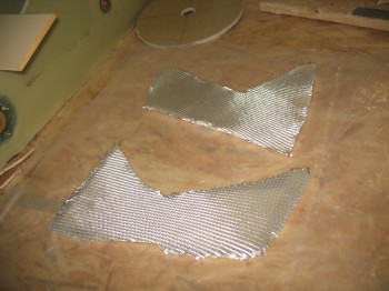
Here’s the resulting form to be glassed, shown first bare & then prepped with Duct tape:
Now, in the pic above I clearly got tunnel vision and the requirement for the contoured bottom of the wedge shaped antenna jack/cover completely eluded me . . . temporarily. Of course once the glass was laid up & peel ply applied, I realized this was not in fact going to work for what I intended it to. Oh, well. I just lost a little bit of time, some scrap BID and a little bit of epoxy. In the end I got a piece that I think will work for the GIB’s headphone jack/cover.
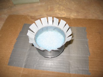
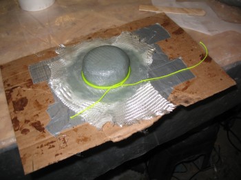
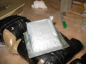
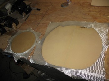
The following pics show the antenna/headphone jack being glassed:
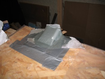
And here they are curing in front of the heater (it was quite chilly weather in Germany even though it was late May).
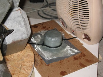
Since I used all fast hardener on these components, I think the much faster curing sealed the glassed pieces to the foam more than usual. The first fuel tank vent manifold cap I made was a bear to get off the form, and I ended up tearing up the somewhat fragile foam form to get it off the darn thing. Thus, I had to make a completely new form for the second fuel tank vent manifold cap. No worries. Also, when I was glassing the 2-ply BID layup, some of the plies separated at the “corner” of the cap. Instead of messing around with pulling the separated ply, I simply added another ply of BID for 3-plies total on the second cap.
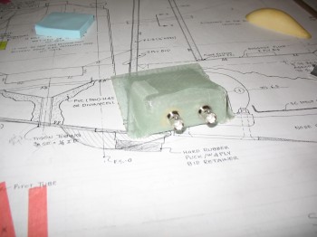
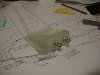
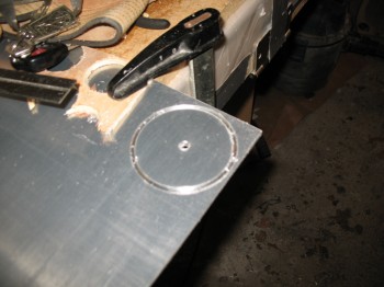
 After I got the second fuel tank vent manifold cap laid up & curing, I then mocked up the first cap to see how it fit. Once I saw that the fit was good I drilled a ~21/64″ hole (I had to use my Perma-Grit tool once I drilled the initial hole so the measurement is an approximate…forgive me Marco for not pulling out the calipers!) and mocked up the AN912 bushing & Nylaseal adapter.
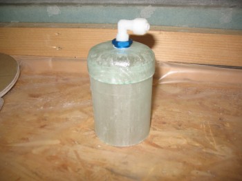 Once I confirmed that AN bushing fit well, I sanded/prepped around the hole on the cap and floxed the bushing into place.
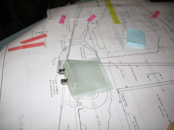
I then turned my attention back the soon-to-be headphone jack cover. First, I pulled it off its form & then drilled the holes for the antenna jacks. I then removed the peel ply.
I installed 2 antenna jacks (I’ll swap them out for headphone jacks) to test the fit. Of course everything is good except there is NO CONTOUR CURVE on the bottom of the jack cover to match the canard.
So this piece is definitely either a headphone jack cover or something else yet to be determined.
I pulled the peel ply off the Right-side NG30 plate, Napster bulkhead & the forward nose bulkhead.
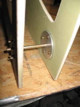
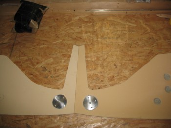
I drilled 4 #12 holes for (not in) each NG8 aluminum mount–using the NG8 as a template–through the NG6 glass hardpoint in the NG30. I also drilled the 5/16″ center hole in the hardpoint for the NG6B front gear pivot mount.
At the back end of NG30 I drilled a 1/4″ hole through the lower hardpoint for the EZ Noselift actuator mount.
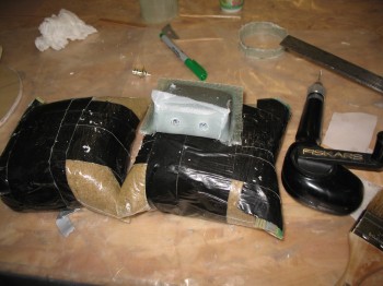
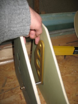
I then mocked all this up as shown below.
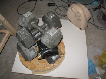
As for the 2 nose bulkheads, I had to put Napster (the larger one) into timeout because he was warped! I weighed him down & put the heat on him to straighten him out.
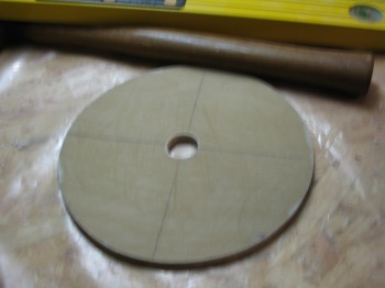
I had laid up a 2-ply BID layup using fast hardener on side B of the front nose bulkhead (smaller one) & then peel plied it. A couple hours later I pulled the peel ply off, sanded the edges, and then drilled a hole in the center of it that will eventually allow the retractable heated pitot tube to retract into the nose.
Next I went into high density foam cutting mode. With the Davenport nose there are 2 additional arms (BC1)–extensions of the NG30 assembly if you will–that lie in between the smaller nose bulkhead (pictured immediately above) and the larger bulkhead we affectionally refer to as Napster, in the Battery Compartment area. So in addition, these BC1 extension arms are notched to hold the Odyssey PC680 battery in place. I cut the 2 BC1 pieces out of H250 high density foam.
I also cut 8 pieces of “scrap” BID for a 2-ply layup that will be glassed on each side of the BC1 battery compartment plates/NG30 extensions. I then glassed side A of the BC1’s (no pic) each with a 2-ply BID layup & peel plied.
Finally, I cut the F4.1 piece that will get glassed on the AFT side of the upright NG30 arms (the front side of the NG30 arms will get glassed to the aft side of Napster).
I started today on the Left NG30 plate. I knife cut the edges & pulled the weight plugs from the hardpoints.
I was trying to find that point in time that is the “sweet spot” for pulling peel ply . . . when it comes of easy & doesn’t leave any peel ply boogers and still leaves the surface nicely textured. However, I have to admit I was a bit hasty in finding the sweet spot, so that’s why the surface of the Left NG30 plate above is a bit shiny vs. the usual dull after a glass surface has been peel plied.
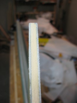
The pic below shows the edge of the NG30, with 4 plies of glass, the H250 high density foam, and then another 4 plies of glass.
Since it took a fair amount of time & a lot of elbow grease on the Left NG30 plate to dig out the foam at the hardpoints, I decided to change up my technique. This time on the Right NG30 plate I used a Forstner bit. I had to be careful, but it worked wonders and cut the time to get the hardpoint holes configured correctly in less than 20% of the time as it did on the Left NG30 when doing it with the Dremel & by hand.
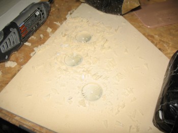
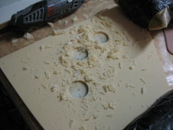
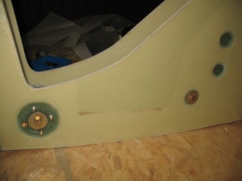
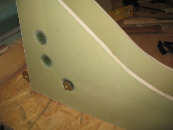
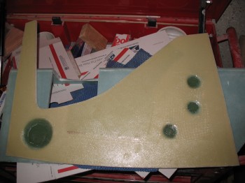
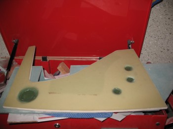
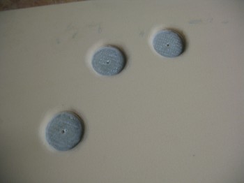
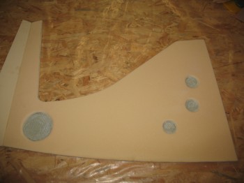
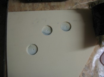 Below is the finished aft 3 hardpoint positions for the Right NG30 plate after the hardpoint divots had been cleaned up, with the following pic showing all the hardpoint positions.
 Before I glassed the Right NG30 plate I grabbed Napster . . .
 . . . and pulled the peel ply.
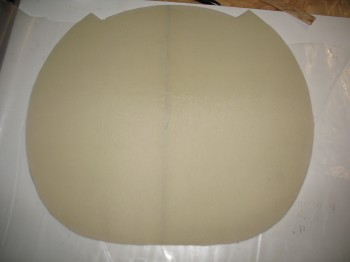
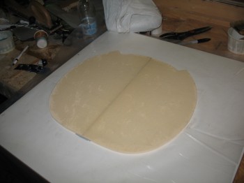
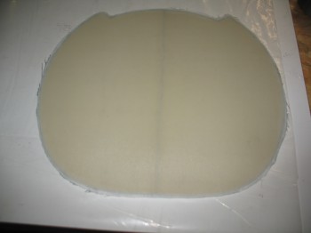
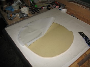 And because I was low on H250 foam, I used 1/4″ thick Birch plywood for the very front nose bulkhead. I marked the outline on the sheet of ply, and then cut it out.
I now had side A of the front Birch plywood nose bulkhead and side B of Napster ready to glass.
I started with the Right NG30 plate by pre-pregging & glassing the 18-ply hardpoint layups, after lining the edges of the hardpoint holes with flox.
I then laid up 4 plies of BID across the entire Outboard surface of the Right NG30 plate. Also, just as on the Left side, I glassed a 1-ply BID reinforcement across the top edge for added strength. I then peel plied the layup & weighed down the hardpoints.
After I got the NG30 situated, I glassed a 2-ply BID layup on side A of the smaller wood nose bulkhead & a 2-ply BID layup on side B of Napster. I peel plied both of these layups as well.
I started today by double-checking the hard point positions using Jack Wilhelmson’s EZnoselift actuator as a guide.
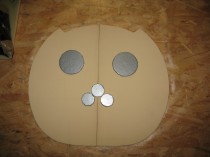
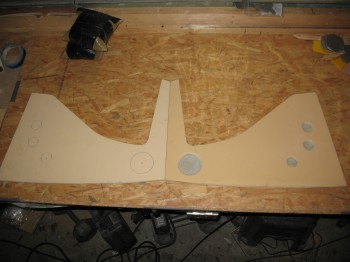
Before I used the paper NG30 template to mark the hardpoint centers, I sanded the NG30 plates’ edges to match.
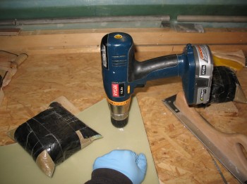
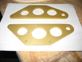
I then focused on cutting 2 each NG8 aluminum disks out of a 0.125 in. (1/8″) 2024-T3 plate. These discs will reinforce the glass hardpoints and will help carry the loads of the pivot bolt that the NG6B Nose Gear Pivot Casting (and the front gear strut) pivots around.
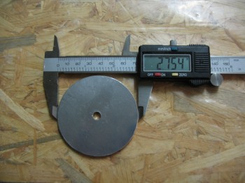 Per plans, the NG8s are supposed to be 2.8 inches in diameter. Considering I’m using a electric hand drill with German metric hole bits, I’ll take my 2.754″ inches diameter and be happy about it.
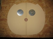
And because I have an incredible sense of humor (yuk, yuk . . . see?!) I had to use these NG8s for Napster’s eyes before I drilled the 4 smaller screw holes:
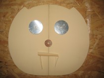
And then here’s a serious shot with the 4 smaller #12 screw holes drilled in the NG8s.
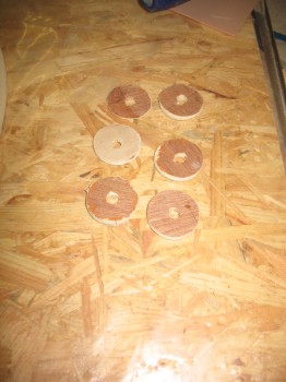
In addition, I drilled a number of circular wooden plates that I covered with tape to use in weighing down the glass in the circular hardpoints.
I then located some scrap BID & set up my pre-preg layups for the hardpoints (shown below).
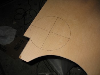
I used my NG30 paper template to transfer the hardpoint centers to my NG30 plates.
I then drilled the marked holes to lock in & ID the center positions of the hardpoints.
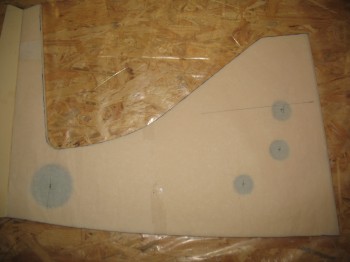
I then marked the outlines of the hardpoints, and starting with the Left NG30 plate, removed the foam down to the inside of the Inboard 4-ply glass. I sanded & prepped the “bottom” of the hardpoint positions for the 15-plies of hardpoint BID that would get laid up into each hardpoint position hole.
I put the paper template back over the NG30 to confirm the correct positioning of the hardpoints. I also set the NG8s (2 pics below) to get an idea how they would look when positioned.
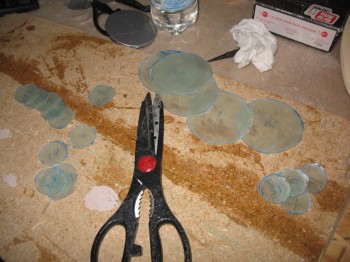
 I wet out the BID in the pre-preg setups & then cut the circles out for the hardpoints. There’s 3-plies of BID in the pre-preg setup, so stacked it will make the total number of BID plies required for all the hard points.
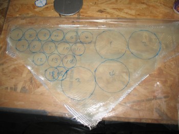
Since the 15 plies came out thinner than I expected, I threw an extra 3-plies into each hardpoint ‘hole’ for a total of 18 plies per hardpoint. Before the hardpoint BID layups were glassed at each point, I had whipped up some flox & spread it around the foam edges to fill in any gaps and irregularities. I then glassed the NG30 Outboard side just as I had the original Inboard side, with 4 plies of BID at alternating biases: 2 plies at 45° & 2 plies at 90°. I also added an extra strip of reinforcement BID (as per Jack’s suggestion) just aft of the front hardpoint and focused on the upper curved section of the NG30… it ends above & just forward of the aft 3 hardpoints.
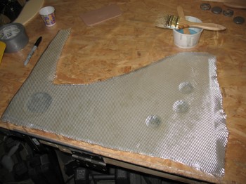
Once I glassed the 4-ply BID layup on the Left Outboard NG30 plate, I peel plied it & weighed down the hard points for a nice tight strong layup at each hardpoint.
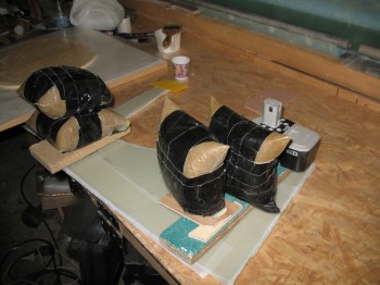 I didn’t like my initial hardpoint weight schema since I didn’t have good eyes-on with the glass surround the hardpoints, so I switched it up to that shown below.
I also micro’d the Napster (large bulkhead) halves together and then glassed a 2-ply BID layup & peel plied it.
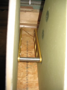
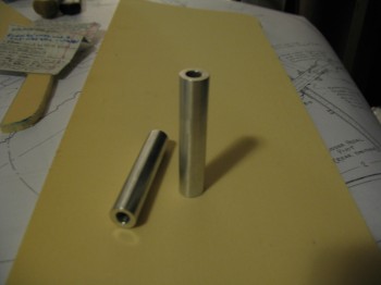
I spent a lot of time at my planning table in the house tonight to figure out my nose & nose gear configuration. I was about ready to ask my buddy Marco if he could machine some NG14 spacers (they sit in between the NG30 sides), but then I found them in the EZnoselift kit that Jack Wilhelmson sent me. And here they are:
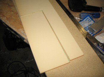
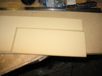
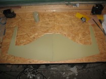
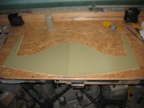
I then planned out and designed the first & larger of 2 bulkheads that I’ll be building for the Davenport extended nose. I did modify it just a bit, because my front nose hatch will be larger than the stock Davenport hatch, traversing the large bulkhead (thus the indentation at the top). Since I was running low on H250 high density foam, and since it’s extremely expensive (for you non-Canardians, it runs about $105 for a 2 ft x 2 ft sheet … yes, it’s that tough as far as foam goes. And tough to cut too!) I used 2 pieces to make up the larger nose bulkhead (this, incidentally, will mount on the front vertical arms of the NG30 plates).
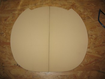 Of course as soon as I got the foam cut out & the bulkhead pieces together, this part quickly was dubbed with the moniker “Napster”.
Finally, I measured out the nose lift brackets & correlated them with the NG30 holes. This had to be done before I continued on glassing the NG30 plates, since the next step is to glass in the hardpoints that will secure & be mounted to these nose lift actuator brackets below.
I didn’t do much today on the build since I was prepping for my upcoming move.
I did remove the can from the fuel tank vent manifold body.
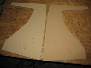
I then knife cut the edges of the NG30 plates & pulled the peel ply.
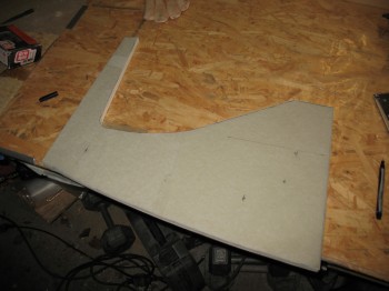
I call these first 2 pics the “F-117 Canard” pics . . .
I stacked the NG30 plates just to make sure I had as near-perfect alignment & symmetry between the two as possible.