Chapter 21 – Right strake leading edge

Today I finally finished mocking up the right strake leading edge.  Again, doing this with the wing on presents some challenges, and again, just like the left strake leading edge —try as I might— I couldn’t avoid cutting the outboard end about 3/8″ short.

This time however I was not going to take the time to reattach some of the sliced off pieces before I glass the leading edge into place.  Since I have to remove the wings soon to both put the fuselage in the grazing position to find the low water mark for the tank drains, and glass the outboard ribs, I figure I’ll just wait until then.

The rest of the install was long but straightforward.  This time I used all EZ-poxy to make it easier and more efficient.  I also was able to peel ply the 1-ply BID tapes around the leading edge that attaches to the fuselage.

Here’s a shot from the front of the fuselage.

I’m using flox on the perimeter tank ribs and micro on the R45 rib.  Even though I went with much drier micro this time, it still flowed out in this one spot . . . right out from under the glass.  Yes, it looks sloppy but I think it will work just fine.

Here’s the modified OD rib, which is the outer fuel tank rib/wall on the forward side of the tank.  I laid up a couple plies all the way around, and of course made them very wet.

For some reason this leading edge fits the ribs just a tad differently than the left side.  I tried 9 ways til Sunday to figure out exactly what was causing it, but every measurement and configuration seemed pretty darn close between the sides.  The right leading edge just seems to naturally rotate forward a hair more than the left side…. although admittedly I had to cajole the left a little more than this side.

The result is the aft bottom flange sits a little farther aft while the top flange sits a hair forward as compared to the left side.  The alignment between fuselage and wing looks really good so I pressed forward with the leading edge install.

Then, at the end of the evening I had some left over epoxy and was actually able to glass the inboard side of the outboard rib.  I’ll have to glass that same section on the left wing once I take the wing off.

Here we have the interior of the right strake leading edge as seen from inside the cockpit. I mocked up the R23 rib and plan on glassing that into the strake tomorrow.

And with that, I’m calling it a night.


Chapter 21/22 – Left strake opening

Today I started out by soldering in a glass fuse assembly onto the GIB Bose LEMO power wire.  I would prefer to use an ATC blade inline fuse but the LEMO requires a 0.25 amp fuse, which are readily available in the glass version but not so much in the ATC blade fuse format.

Once I soldered the wire I then covered it with red heat shrink.

And then knocked out the other side.

I then spent a bit of time measuring/cutting/shaping a foam bracket to add another securing hardpoint to the 3 fuel lines, all on the front seat right sidewall.

Fast forwarding a few hours, here’s the foam fuel line bracket secured with a 2-ply glass layup: 1 ply of UNI and 1 ply of BID.  Yeah, it’s a bit rough, but it does the job.  I did take a few minutes to clean up the potentially finger-snagging glass after I took these pics.

Along with the composite fuel line bracket —10″ upstream from the previous fuel line bracket located at the pilot seat bulkhead— I spent a few hours finalizing the wiring & cable management at the front seat right sidewall.  This effort resulted in the right side fuselage cable runs complete from hell hole to instrument panel.

Here we have the installed ELT antenna with the actual antenna aerial set inside a painted 1/8″ Nylaflo tube.  I had thought about hard-installing the ELT antenna inside the Nylaflo tube but decided against it. In this configuration this Nylaflo tube allows me to remove and install the ELT antenna when I need to, whereas if I had hard installed it I would have had to do major surgery to remove it if need be.

My final check was replacing the right front armrest to ensure clearance with the upper and lower wiring bundles.

With the main centerline fuselage tasks out of the way, I then turned my sights on the final task of the evening: the left strake fuselage opening shaping and glassing.

Here’s the before pic of the opening.

I then spent over an hour dialing in the shape of the sidewall to continue the angle of the left strake leading edge inboard to the inner edge of the fuselage sidewall.

After I got the sidewall opening edge shaped, I then drilled a couple small holes to allow me to run a couple wire pairs from the aft side over the strake opening (for cockpit lighting) and a pair just forward of the canopy latch opening (for the canopy latch warning switch). Note the wires exiting the sidewall forward of the instrument panel.

After I ran the sidewall wiring I then glassed the strake leading edge-to-fuselage sidewall intersection with 1 ply of BID. I then peel plied the layup.

Quite a few hours later I pulled the peel ply and did a quick cleanup of the layup.

Out of curiosity I checked to see how far into the fuselage this continuing on of the strake leading edge intruded into the interior sidewall… almost 2″.

From here on out my next focus will be on installing the right strake leading edge.

Chapter 21/22 – More strakey stuff

Today I started out by tweaking my task sheet, reviewing the strake build steps and generally just trying to ensure I don’t screw anything up… or forget something until it’s too late to do. Or really friggin’ difficult at that point.

Out in the shop the main task was to finish glassing the modified/extended BAB baffle.

First, I had glassed it on the aft side with a 2-ply BID tape outboard, but still needed to trim a corner off the actual fuselage sidewall and then glass the interior side.  Here’s what it looked like starting out today.

And a shot showing the fuselage sidewall edge that I’ll trim.

And here it is trimmed.  I just set my Fein saw (Harbor Freight version!) blade up against the BAB baffle and simply used it as a guide.  A few minutes later I was done.

I then laid up another 2-ply BID tape using MGS epoxy on this side.  I then peel plied the layup.

Quite a few hours later the layup was cured and I pulled the peel ply and did a quick cleanup.  It looks good and I’m happy with the results.

After finishing the above layup, I got to work sanding down and prepping the front side of the modified/extended BAB where it connects to the R23 rib.  I didn’t get to this layup when I installed the 2 baffles in the left strake since there was a support board hanging down in front of this corner.  When I did the original layup on the other side I could see the flox bead in this corner and actually used my scribe to get in there and smooth it out and clean it up.

This time around I did add some more flox after scuffing up the original, smaller flox fillet. Since this is an internal fuel tank corner on the perimeter I used a 2-ply BID tape here.  I laid it up as wet as I could and also peel plied just the top and bottom strips that will get more overlaying glass.

A wider angle shot showing the entire interior fuel tank side of the BAB baffle.

To reiterate, I am doing a round of final internal cockpit component tasks before I mount the right strake leading edge.  Here are all the wires from just the top wire bundle that I’m sorting out (read: wrangling).

Here’s another shot of these wires.  I included this pic because the right front wall will be a priority to finish up some tasks before the right strake leading edge goes on.  I’ll detail more tomorrow as I get this stuff knocked out.  To be clear, before the right strake LE gets mounted, all the wiring —both top and bottom wire/cable bundles— in this area will be secure and operational up to the instrument panel bulkhead.

I had planned on doing more tonight, but had some personal calls that I needed to take so I lost a good couples hours there… I’ll be back on it tomorrow.

Chapter 18/21 – Left strake verticals

I started off today working on the small diameter 1/4″ fuel tubing that vent each GIB thigh support sump tank into the main tank.  These guys, left and right, have been sticking up like little flag poles since the day I installed them.

Before it gets a little too tight in that back corner –once I install the extended BAB baffle– I wanted to bend them 90º and trim them down in length.  I was actually thinking of securing them to the side wall at this point, but since I’m going to add a layer of BID over the existing corner I figured I’d wait.  And I’ll still have decent access to that back corner for glassing by coming in from behind the CS spar.

Here are the 1/4″ thigh support sump tank fuel vent lines bent 90º and cut to length.

I then spent the next 3 hours + prepping and installing the extended BAB (inboard) and DB (mid tank) baffles.

A couple shots from below . . .

I used the plans layup schedule with just 1-ply BID tapes to secure the pieces together, both for the rib attach and now the baffles too.  However, where the junction is on the external perimeter fuel tank wall I use 2 plies on the interior tank side just to ensure I have no leaks.

For example, the leading edge “nose” of the R45 rib only got a ply on each side, whereas the inboard leading edge “nose” of the OD rib got 2 plies, as did the outboard edge of the R23 rib “nose.”  For these 2 baffles only the extended BAB got 2-ply BID tapes on the internal side since it makes up part of the perimeter wall of the fuel tank.

Here’s a shot of the baffles looking inboard.

And a couple shots looking aft.

Here we have the extended BAB and DB baffles installed, viewed from the cockpit side.

And a last shot of the extended BAB —due to the “GIB elbow room mod”— from inside the cockpit.  If you look at the aft/left end of the BAB you can see that I still need to trim down a small wedge on the fuselage sidewall aft opening, sand a nice smooth transition and then glass that back corner.  Here I will be using 2 plies of BID since this back corner is also structural.

Before I remove the duct tape from the outside of the left strake leading edge I wanted at least some internal glass securing the LE to the fuselage.  I have glass on the external side, around the perimeter of the LE where it mates to the fuselage, but had nothing internal until I used the Fein saw to knock off a bit of the sidewall edge and then sanded a nice transition from the exposed screw aft.  I laid up a ply of BID and then peel plied it.

Unlike the plans version, a nice feature on these leading edges is that you get a nice curved wing-leading edge-shaped entrance into the cockpit vs. a blunt squarish presentation. However, it will require trimming away a lot more of the inside edge of the sidewall to continue the angle of the leading edge all the way inboard for a seamless transition.  So this was just a quick fix before I knock the rest out (at least plan to) tomorrow.

In addition, since I still have better access to the front seat area with the right strake leading edge not mounted yet, I knocked out glassing the exposed top edges of the pilot seat.  If you’re wondering why I didn’t do this earlier before I painted the cockpit interior, so am I… Doh!

My last task of the evening was finally adding in the #4 hardpoint for the canopy handle lever assembly.  Since I ran the Nylaflo wire transition through the bottom edge of the canopy handle fuselage opening, I was then cleared hot to get this RivNut floxed into place.  I carefully drilled and then prepped the hole before bolting the RivNut to the pre-taped (to protect against errant flox gunk) canopy latch handle.  I then slathered up a bit of flox in the hole and on the RivNut and simply bolted the latch handle back into place. Voila!

Tomorrow will be a bit more work in the cockpit area since my time for unhindered access is coming to a close.  My plan is to either fit and mount the right strake leading edge, or at least have it prepped for install the following day.  Either way, I’m happy to be having significant movement on the strake build!


Chapter 21 – Right Troika Ribs

I did a little clean up starting out today on the left strake R45 rib mouse holes… some glass overhanging the edges of the mouse holes that I removed.  Although the layups look a bit sloppy due to the copious amounts of filling flox, I’m really pleased with how these ribs came out.

My main goal today was to get the left side BL23 rib installed, but I wanted to get all the commotion, vibrations, etc. out of the way on the right outboard ribs first, what with sanding and using the Fein saw and all.

I started by marking the top and bottom cut lines on the aft fuel wall that sits in between the R45 and modified OD rib.

I then trimmed the aft fuel wall as well as beveled the front “nose” sections of the R45 and OD rib.

I then got to work on the left side BL23 rib.  I used a piece of wood coming down from the cross level to secure the rib while I floxed and glassed it in place.

Here’s the left strake BL23 rib as viewed from the outboard side.

And a shot through the BL23 aft inspection port to view the fuel drain. Note the 1-ply corner BID tape securing the BL23 rib to the CS spar, as per plans.

The front layups on the BL23 rib outboard side . . .

And the inboard.

From the very front side of the strake leading looking aft.  Again, a 1-ply BID corner tape securing the BL23 rib to the CS spar.

And more of high vantage point shot.

Tomorrow I plan on getting the BAB and DB baffles installed on the left strake.  I also plan on dialing in the right strake leading edge in prep to install it as well.


Chapter 21 – Left strake leading edge

Today was all about getting the left strake leading edge installed… which I was able to accomplish.

I did have a prerequisite task to accomplish first: run a 1/4″ diameter Nylaflo tube from the front edge of the strake opening to behind the panel via the bottom edge of the canopy latch handle opening in the fuselage sidewall.

Here’s a before shot of the canopy latch handle opening.

And then a shot after I dug about a 1/4″ trough down through the middle of it.

I then used a medium-long drill bit to drill from the front seat strake opening edge into the canopy latch handle opening trough, as you can see the bit traversing here.

And this is what the actual operation looked like.

I then used a much longer 1/4″ bit to allow me to get behind the panel.  I then reversed drilled at a very shallow (or steep, depending how you call it) angle to allow for a nice egress from the side wall of the Nylaflo tubing.

Here’s a another shot of it.  At this point you might be asking, “Great, but what is it for?” … Good question.  I’ll be running 2 pairs of 22 AWG wire through this tubing to allow mounting 2 switches that will control cockpit/map lighting in the front seat.  Actually, I’ll probably dive in another pair of wires at the front edge of the canopy latch handle opening for the canopy warning microswitch.

And both ends of the Nylaflo tubing will be trimmed flush with the fuselage sidewall.

I then whipped up some micro and micro’d the Nylaflo into the canopy latch handle opening trough.  I then peel plied the micro.

Fast forwarding a few hours, here it is after it cured and I pulled the peel ply:

I then trimmed the inboard edge of the right strake leading edge before mounting it onto the fuselage, along with the left strake leading edge.  To be clear, I still need to trim the outboard right strake leading edge before it’s ready to be mounted.

The purpose for mounting the right strake leading edge was to get a good assessment on the B23 baffle and R23 rib in joining them together.  Matching the waterline marks seemed to be spot on, so that was the plan to glass these together.

Here we have the R23 rib as seen from inside the front fuselage strake/baggage area opening.

Fast forwarding a number of hours, here we have the right strake R23 rib combined with the B23 baffle as one piece.  I glassed this first thing out fo the gate before I started in on attaching the left strake leading edge.

I spent a good bit of time –an hour plus– cutting out al the BID tapes for the left strake leading edge install.

I also had drilled and set position screws on every rib to ensure I got a repeatable alignment once I got the left strake leading edge where I wanted it.

I also hot glued and clamped a small wood block on the bottom of the fuselage forward strake opening to ensure the bottom of the leading edge was aligned properly.

Here’s a closer look from the outside of the fuselage.

And a closer look from the inside of the fuselage.

I also did the same thing on the top side to ensure the leading edge top flange was set in the correct position.

I then installed the left strake leading edge.  Here’s a shot of it attached to the fuselage forward strake opening [Note the Kevlar strip inlay on the interior LE].

And although not the prettiest layup, here is the inboard side of the R45 rib showing how it is secured in place.  I used 1 ply of BID here on each side.

And then the modified OD rib that makes up the forward part of the fuel tank outer wall.  I used 1 ply for the aft 3rd of the top joint followed by 2 plies at the rib nose and along the bottom junction with the strake leading edge.

After 3+ hours of scrambling, here’s the left strake leading edge installed!

And a closer shot of the forward end of the strake leading edge that’s attached to the fuselage.  I will say that I was hustling so quickly that I just wasn’t able to peel ply these perimeter layups around the front part of the leading edge.

I had also planned on installing the actual R23 rib, but it just got so late that I’ll punt that off until tomorrow.


Chapter 21 – More Kevlar!

I started out today by pulling the peel ply and cleaning up the left strake leading edge Kevlar +1-ply BID layup.  The layup looked fine, and you can see some bits of it in the shots of the ribs below.

To mock up the left strake leading edge I first needed to trim the outboard aft fuel wall to height, both on the top and the bottom.  Here you can see the top trim line I marked on the outboard aft fuel wall.

After I trimmed the aft fuel wall, I sanded the “T” junction smooth.

I then spent about 3 hours dialing in the fit of the left strake leading edge with the outboard group of 3 ribs: the R45 rib, the OD rib, and outboard rib.  Part of that process included a 30 minute interlude where I remounted the double-stacked magnetometers much further aft on their phenolic mounting plate.  This had to be done since I had to unexpectedly shave so much off the forward top edge of the OD rib.  In their previous mounted spot the magnetometers simply would not have fit under the strake leading edge interior skin.

Here we have the left strake leading edge in its dialed-in and ready for install configuration.

And here’s the R45 rib prepped for the left strake leading edge.

And the finely tuned (and much work required) modified OD rib, also ready for the LE install.

With just a few more preliminary steps to knock out, I plan on installing the left strake leading edge tomorrow.

Tonight my last task for the evening was laying up the 4″ Kevlar strip, with a 1-ply BID top layer, into the inside of the right strake leading edge. I peel plied the rib junctions and then left it alone to cure all night.

As I said above, my plan for tomorrow is to get the left side strake leading edge installed, then get the right side prepped for installing the following day.


Chapter 21/22 – Electrics n Strakes

I have to say my schedule has been a bit wonky over the past few days.  My friend needed to tend to some medical stuff, so I’ve spent a decent amount of time watching her daughter (aka my little buddy) and haven’t really been able to get back on the build until late this afternoon.

I will say that in the last few days I was able to get the engine flipped back upright, add some new oil and refresh all the top plugs and large drying tub with refreshed desiccant.

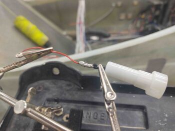
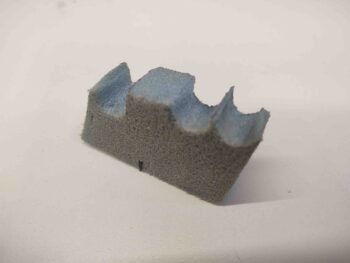
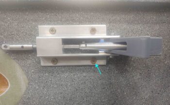
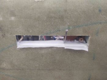
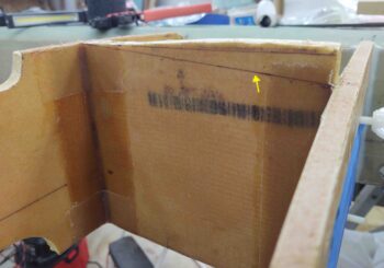
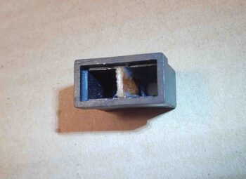
I’ve been working another sideline project here and there for the last few days as well: my dual-light Korey annunciator.  I started off with a spare Korey Light back case:

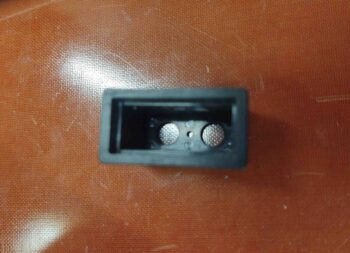
Then when I had some leftover flox I trimmed a 1/16″ thick piece of phenolic to fit inside of the Korey case and floxed it in place.

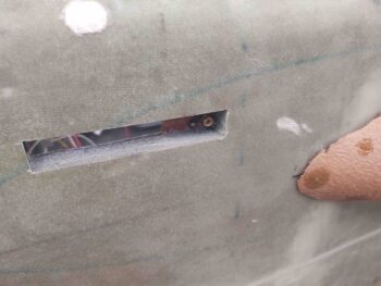
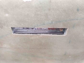
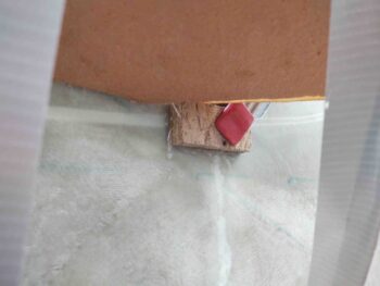
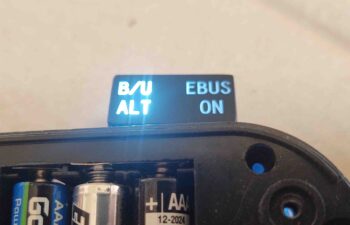
The floxed divided case sat in that state for a few days before I was able to find some decent LED lights to test it out.  Here you can see a slight overflow of the light from the lit “B/U ALT” indicator slightly illuminating the “EBUS ON” side.  I had suspected it might do this since the actual label faceplate is a piece of clear plastic that is painted black.

Since I was running about I forgot to grab any pics of my fix action, but I’ll describe as best possible:

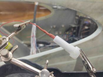
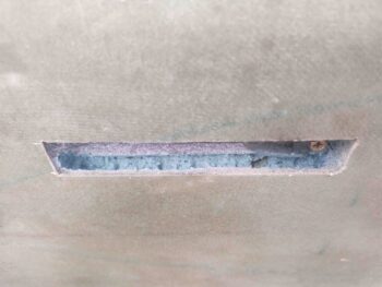
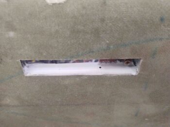
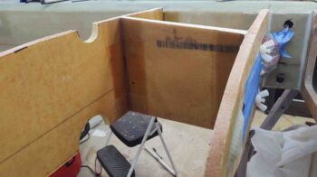
I marked a line on the interior of the face place that mirrored the floxed-in-place divider piece.  I then Dremeled a channel on the interior side of the face place, again aligned with the divider piece inside the back case.  I then filled the freshly Dremeled channel with black gasket maker goop and let it cure for a couple of hours.  It still wasn’t completely cured when I mounted the faceplate into the light back case.  This squished the semi-cured gasket material onto the recently-added phenolic center divider:
A) preventing any light overflow from a gap between the divider and faceplate, and
B) minimizing any light travel through the actual clear faceplate from one side to the other.

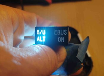
My hypothesis regarding minimizing the light overflow proved correct, and I was very happy to have a successful test of the B/U ALT (“SD-8”) and EBUS ON Korey annunciator light.

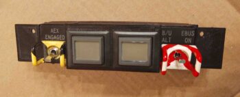
In addition, over the past 4-5 days I’ve been slowly taping off, painting and touching up the red candy stripes on the once white-only B/U ALT and EBUS ON switch guard. Sometimes you just gotta have fun and add a little bling to your build!

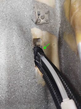
Currently I have 2 each x 10′ long RG-400 antenna cables in my possession.  I know one was for my plan to place the Trig TT-22 transponder antenna out on the end of the right strake (I have it located in the nose now).

The other antenna cable was in response to info I received from the AeroLED guys on mounting their NAV/Strobe lights… and keeping the wing light wires away from any COM antenna leads.  I thus planned on running a COM antenna lead to the engine side of the firewall through an aft able conduit via one of the aileron shear webs.

However, I’ve talked with a few guys at Rough River over the past few years who were running AeroLED NAV/Strobe lights and none of them had any noise or static issues. And nearly all of these were upgrade installs. With multiple reports of no noise issues, I decided to not make the build any more difficult than need be, and just run the COM antenna leads through the wing wire conduit as per plans.

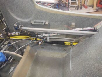
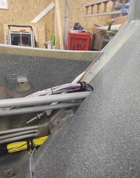
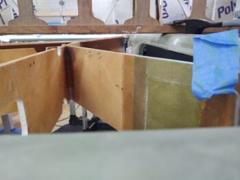
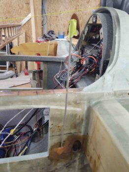
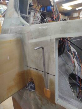
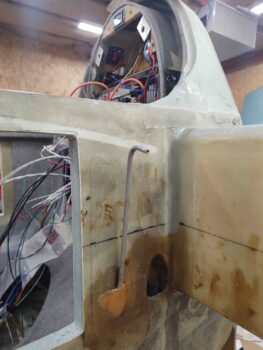
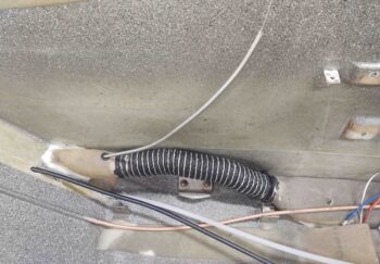
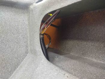
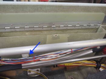
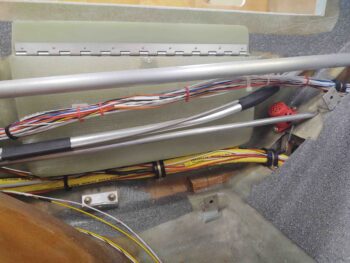
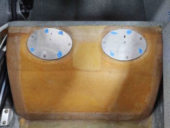
This did leave me with 2 antenna leads that couldn’t make it out the end the CS spar from behind the panel.  Since I have permanently mounted 1″ diameter conduits from the respective outer spar faces to their interior CS spar bulkheads, I tested inserting and running BNC terminated antenna cables –both male and female– through the conduit while it had all the other wing light wires run through it as well.

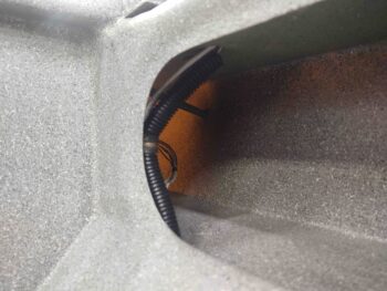
BNC connector space wasn’t an issue at all, so I made a command decision to use what I had on hand and just run the RG-400 from the panel to just inside the CS spar GIB big oval access hole. I figured the fuselage is where the main antagonizers regarding antenna lead noise would be located anyway, so the RG-400 would be put to good use for the fuselage segment of the antenna runs since it’s clearly a bit better shielded than RG-58.

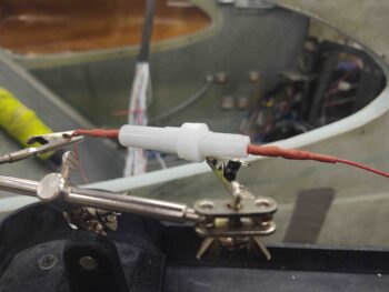
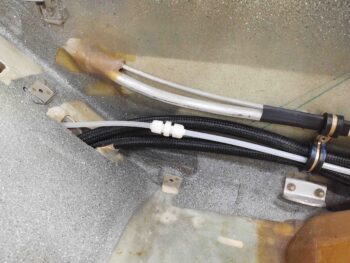
Speaking of RG-58, I’ll add about 3′ to the wing COM antenna leads and actually connect/disconnect them during wings ON/OFF ops from inside the plane, just outboard of the CS spar oval access hole.

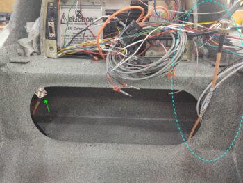
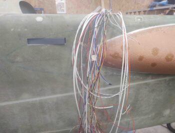
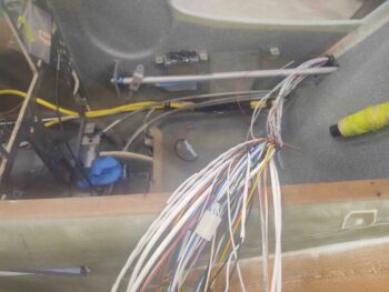
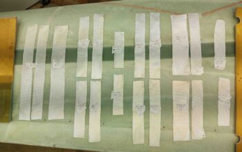
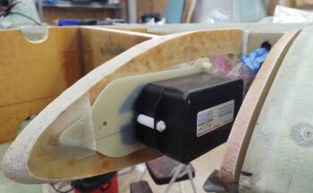
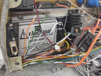
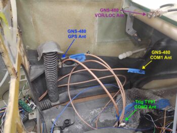
Here are all the COM and GNS-480 related antenna cables.

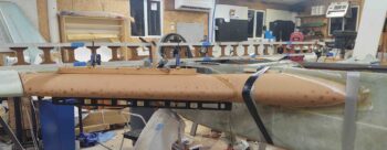
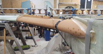
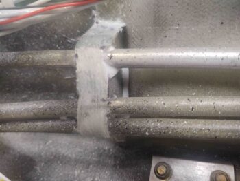
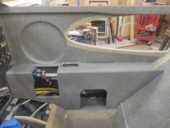
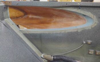
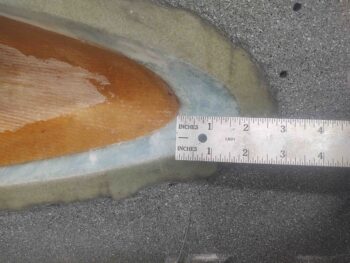
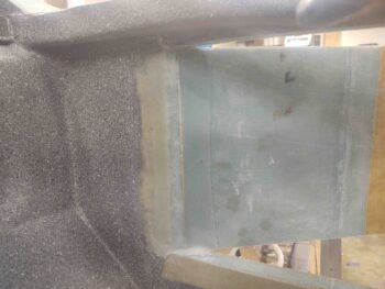
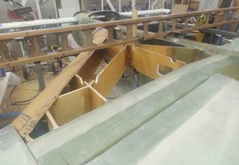
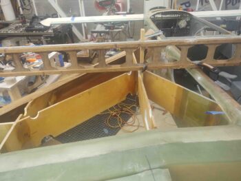
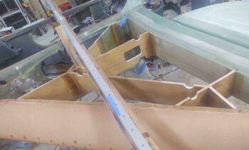
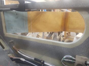
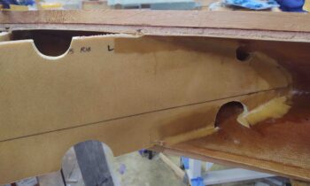
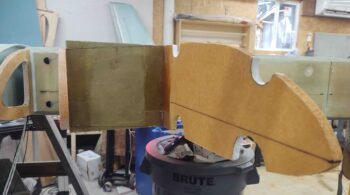
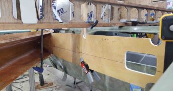
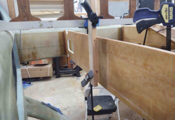
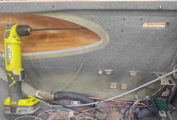
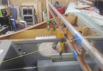
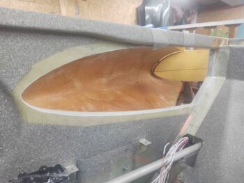
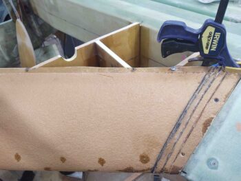
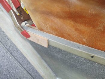
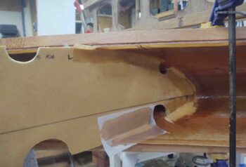
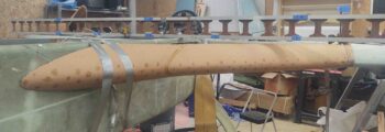
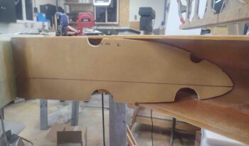
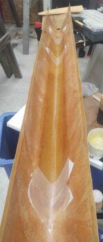
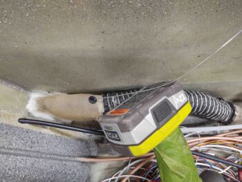
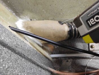
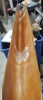
Tonight I finally got busy prepping the left side interior strake leading edge for install by measuring and cutting out a 4″ high by 50″ wide (the width of the fuel tank) ply of Kevlar. Since I’m using these prefab strake leading edges, I don’t have the foam and glass “crush zone” that the plans strakes do, so I’m adding a ply of Kevlar –covered by a ply of BID– on the interior leading edge, as well as a ply on the exterior leading edge.  Although it adds a small bit of weight, it will give me piece of mind that my wet leading edge shouldn’t catastrophically come apart if I experience something along the lines of a bird strike.

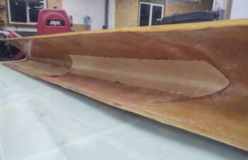
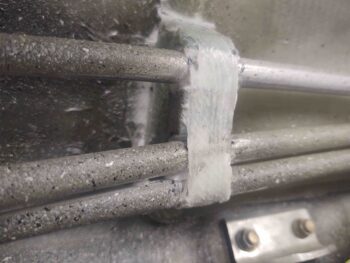
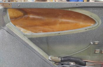
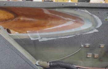
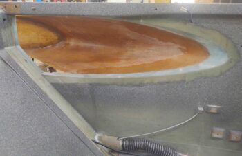
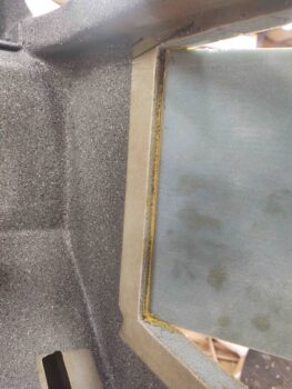
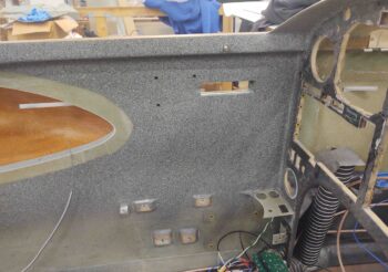
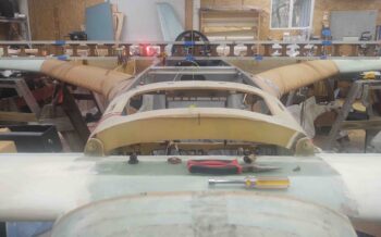
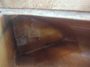
Here I’ve laid up the ply of Kevlar (actually 2 pieces overlapping) with a ply of BID over it. I didn’t prepreg these layups so this was a bit of practice in free handing decent sized layups.

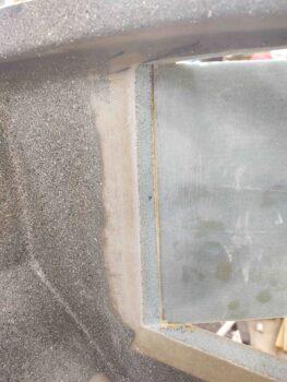
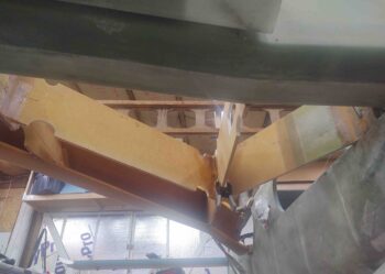
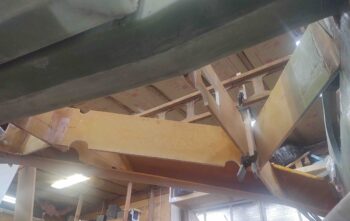
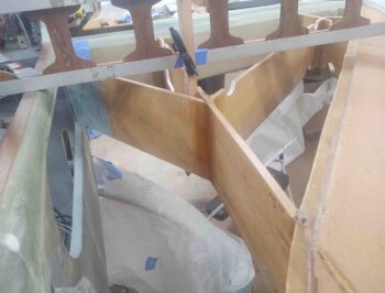
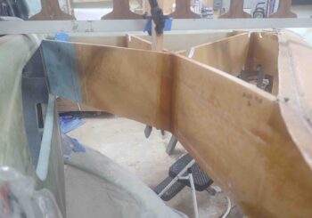
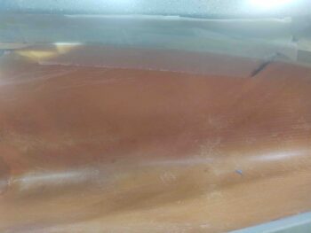
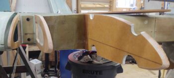
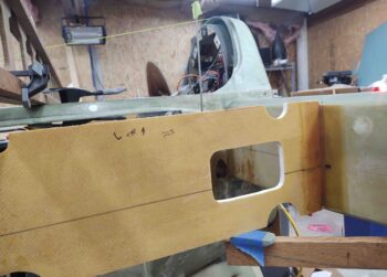
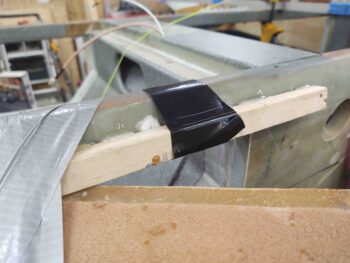
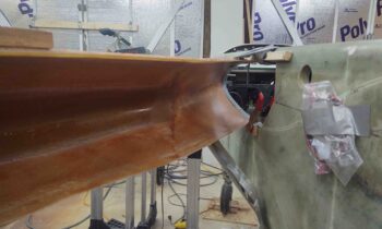
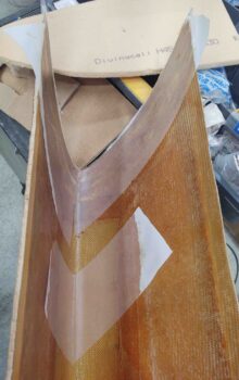
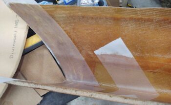
And another shot, a bit longer view . . .

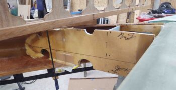
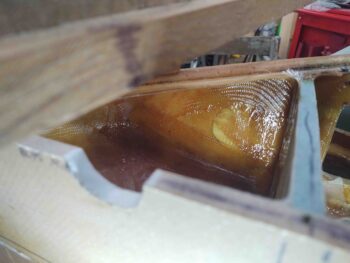
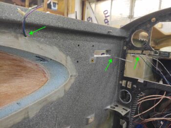
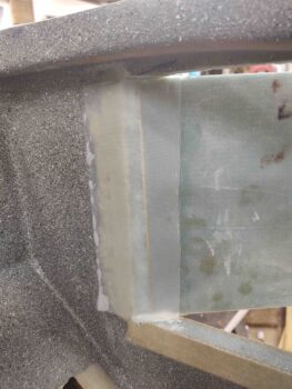
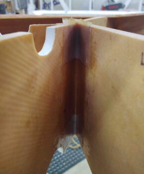
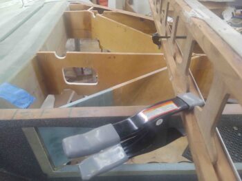
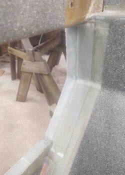
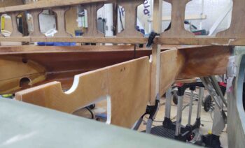
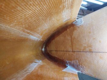
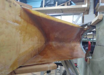
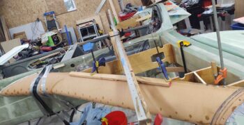
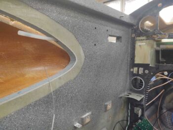
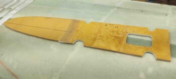
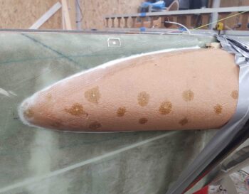
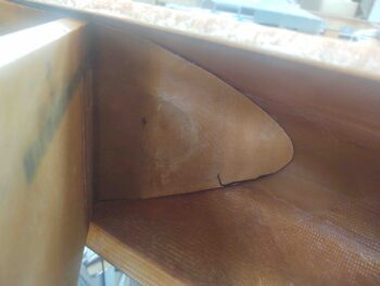
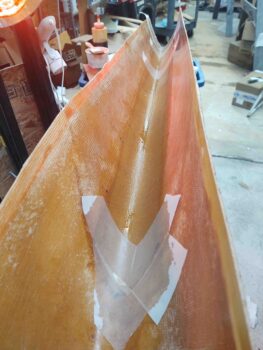
I also took the time to add a ply of BID to the end of the left strake leading edge structure to help repair/reattach all the slices I initially removed and then micro’d back into place.  As you can see I peel plied this layup, as well as any points where the leading edge will intersect the front edges of the strake ribs.

Ok, tomorrow I do plan on continuing with the strake prep and build!

Chapter 22 – Yep, spinning wheels

Today I started off having to do a fair number of errands and personal stuff.

Then I planned on knocking out a few quick tasks before moving on to the strakes.

When I got into the shop mid-afternoon the first thing I did was check out the heat/air duct install.  The install was good so I grabbed a pic and then moved on.

Then, to ensure the relief tube doesn’t get sliced up by the sharper edge of the rear seat bulkhead, I first taped it to the oil heat line right beneath it with 2 plies of the thick Gorilla duct tape and then zip tied it as well.  Note that the zip tie itself is compressed in the narrow slot in the seat back as a sort of protective lock to keep the lines secure and chafe free.

To get some stuff off my work bench I then quickly measured and attached some flexible plastic cable covering/conduit over the wire bundle just inside the back seat CS spar oval access hole. I started on the lower segment beneath the Adel clamp.

When I got to the upper segment I was surprised to pull out the un-terminated and loose 6-wire cable #1 (yellow arrow), that comes in from the panel, from out of the CS spar . . . oops!

First, I ran the 6-wire cable up into the D-Deck.

I then stripped off the outer sheath and separated out the 6 wires.  I had planned on splicing in all the appropriate wires, but needed to label the wires first.  I went back into the house and attempted to print out these 6 labels when I found that I only had enough material for 2 labels… so I was only able to splice in and label two of these wires.

No worries.  Running the 6-wire cable into the D-Deck and getting 2 of 6 wires connected up is a lot farther along than when I started out the day [although in my own mind I had already completed this!]  I’ll order more label cartridges and finish the last 4 wires when I get a chance, even if that means post-strake build.

While I was working these wires, I took a break to pick up my little buddy and watch her for a few hours for my friend.  This of course changed my plan for the rest of the evening.

After I worked the wires above, I then quickly put the piece of flexible plastic cable covering/conduit over the top side of the wire bundle.  I’ll permanently secure these plastic cable covering segments later when I confirm there’s no more wires to be run.

My last act of the evening was to flox the upper wiring bundle “bridge” to the right fuselage sidewall… around the Dynon intercom [I had trimmed and sanded the bridge earlier in the day, and then primed, painted and clear coated it throughout the day].

Ok, so at the risk of sounding like the boy who cried wolf, I do sincerely plan on getting back to work on the strakes tomorrow . . . (we’ll see, ha!).


Chapter 21/22 – Prereq Encore

Well, as I was consolidating my to-do list I realized I had a few holdovers of tasks that I had intended to knock out along with the pre-strake prerequisite tasks.  These tasks are close enough that I decided today to just get them off the plate.

The first task was creating a “bridge” around the Dynon intercom on the right front pilot sidewall to facilitate routing the upper wiring bundle to keep it wrangled and clear of the lower control stick tube.  I started out by taping everything up to protect it from errant epoxy.

Here’s a lower/straight on view of my protective tape job.  Note the new test fit/install of the Adel clamp in the RivNut hardpoint over on the left . . .

I then prepregged and laid up 6 plies of BID around the very lower edge of the Dynon intercom.  Again, this “bridge” will allow me to route and secure the upper wiring bundle and should keep it out of the way of the lower control tube as it swings outboard towards the sidewall during normal flying ops.

Moving aft, I also added a dollop of 5-minute epoxy to the center of a peel and stick wire tie point on the forward half of the GIB right armrest storage bin.  This tie point is to further secure the upper wiring bundle in that area . . .

As you can see here:

I then did a little more work on the heat/air duct system by first securing the SCAT tubing to both the aft side duct assembly and the forward duct assembly. This required trimming the SCAT tubing a bit shorter.  I then micro’d the aft duct assembly into the lower left pilot seat back bulkhead and laid up a narrow piece of BID on each side and the top.

Here’s more of a side view.  The cordless drill is providing a bit of weight to keep the aft duct assembly positioned in the seat back channel nice and tight.

Here’s a shot of the front side of this SCAT tubing, connected to the intermediate 3-way duct assembly.

Again, back in the rear seat area I trimmed up both the forward and aft relief tube segments before tying them together with a nylon connector.

My last task of the evening was to remove all but 3 screws out of each GIB thigh support sump tank cover plate.  Since these are easily accessible now, this will just help make it easier to get into the sump tanks later on down the road after the strakes are installed.

Ok, tomorrow I really do plan on getting back to work on the actual strake build!