Chapter 25 – Wing-strake seam glassed

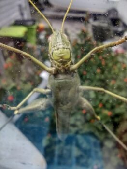
Ever feel like you’re being watched?  As I stumbled into the kitchen to grab my morning coffee this morning I saw this huge bubba on my kitchen window staring me down.  He had to be nearly 5″ long.   His buddy was a “normal” sized grasshopper that was about a foot away, that he completely dwarfed!

(It’s been awhile since I’ve posted a critter pic!)

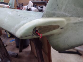
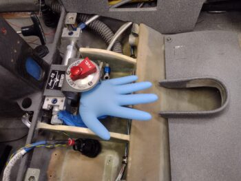
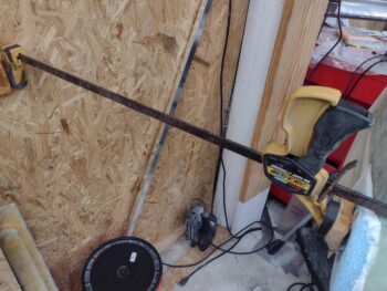
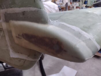
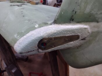
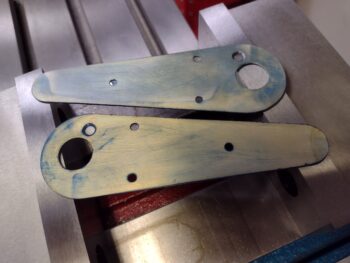
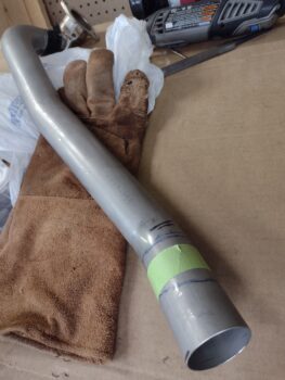
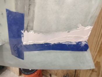
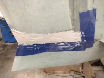
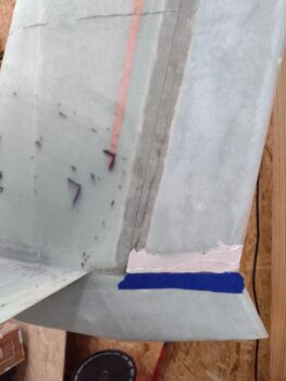
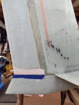
Before starting my adventures on glassing the wing-to-strake transitions/CS spar top fill, I whipped up some micro/410 and applied it on the bottom inboard edge of the rudders.

As time permits I’ll be playing around with glassing in winglet-to-wing intersection fairings to eliminate the washup air that happens from the end of wing higher pressure airflow spilling upwards and disrupting the straight airflow across the bottom of the rudder.

Here’s an oil test that Dave Berenholtz performed showing this roguish air in action… I lifted the pic off his awesome build site.

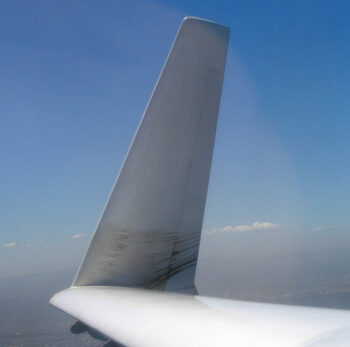
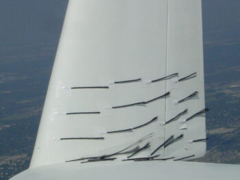
James Redmon of Berkut 13 fame described it as air “departing the intersection in a fan shape and climbing up the winglet.”  James did a good bit of tuft testing before also adding a winglet intersection fairing and here’s a shot he took that I nabbed off his site as well.

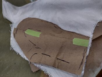
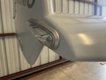
And here are the fairings that wrangles this wayward air.  First Dave B’s winglet intersection fairing:

And then James R’s fairing:

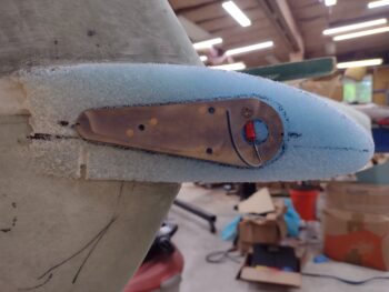
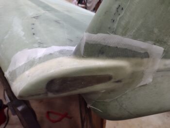
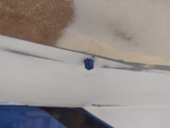
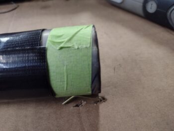
Here we are time traveling ahead many hours to show the rudder micro about 90% cured and after I removed the surrounding protective tape.

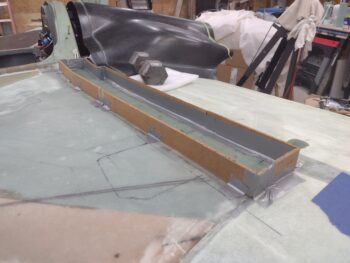
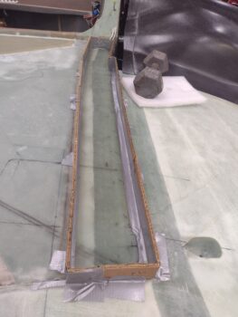
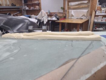
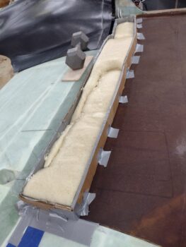
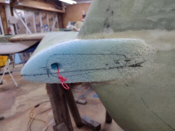
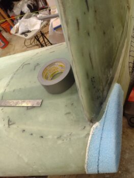
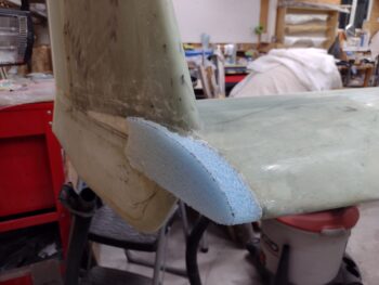
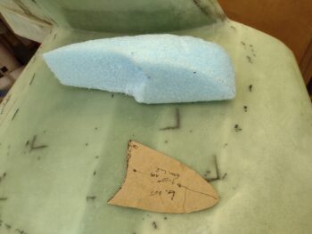
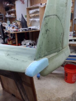
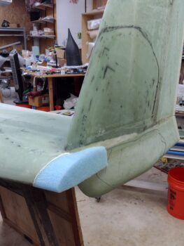
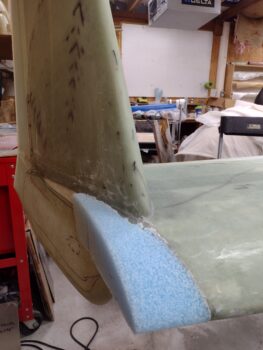
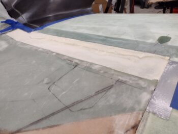
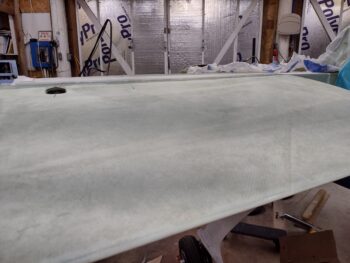
Back onto the strakes… I spent a good 20 minutes sanding down the added foam that I poured into the shallow trough along the top of the CS spar.  Here’s a low angle shot of that.

And a higher angle shot as well.

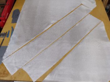
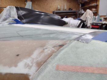
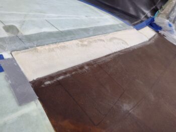
I wanted to minimize as much weight as possible, so I went with a ply of UNI first and then a single ply of BID… both overlapping a hair over an inch onto the front edge of the wing on the aft side and about a 1/2″ past the foam on the front side.

I made sure to keep the front side edge of the layup on the aft sloping side of the slight flox “peak” that was created from when the top strake was closed out and top strake skin added.  This will create a very slight valley that will need to be filled with micro during the finishing process, but it keeps the layup glass off the peak top that would only add height to the already highest point in the area.

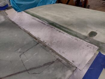
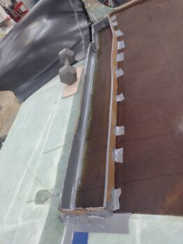
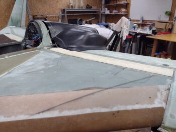
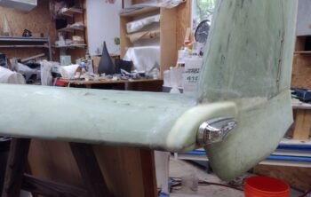
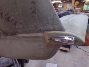
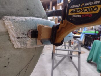
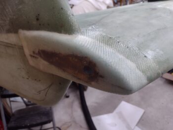
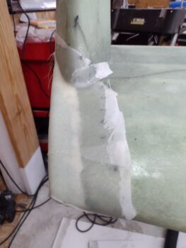
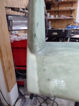
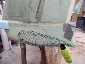
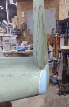
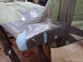
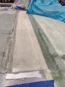
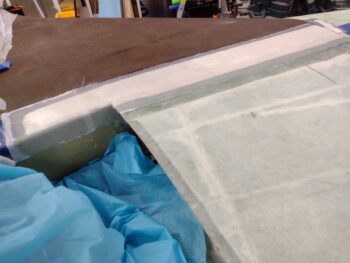
Here we have the 2 plies of glass laid up and wetted out.

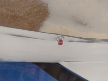
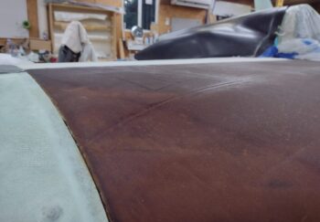
Again, I’m knocking out 2 tasks in one layup here in that I’m 1) covering the added foam that fills the very slight trough on the CS spar while also 2) covering the considerable gap between the wing and strake intersection.

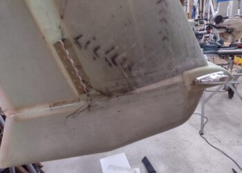
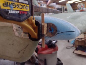
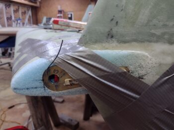
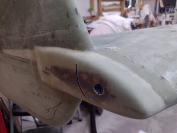
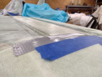
I’ve got my cut line marked (each side) and after the layup cures I’ll simply cut down the line to create the hair-wide intersection between strake and wing.  After each wing is removed I’ll dig out all the foam underneath (I added a 1″ wide strip of peel ply over the length of gap before glassing) on both the wing and strake sides, fill the slight gap with a thin bead of flox and then layup a couple of supporting plies of BID from the underside to reinforce these intersection lips.

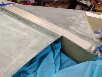
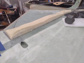
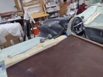
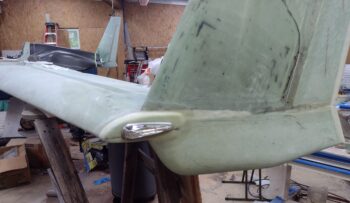
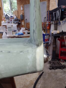
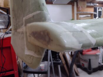
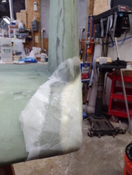
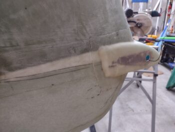
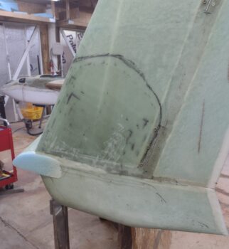
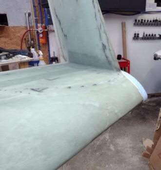
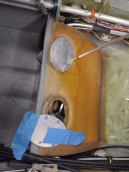
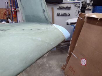
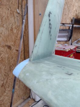
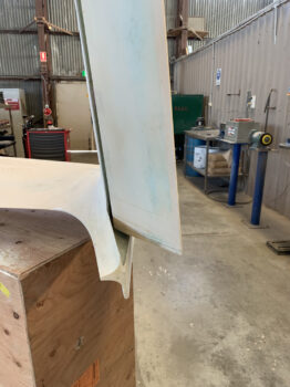
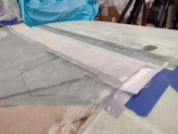
One longer shot of the shaped left strake pour foam fill glassed.

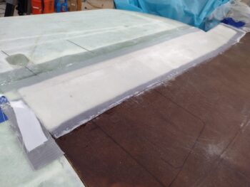
I then peel plied the left strake/CS spar layup.

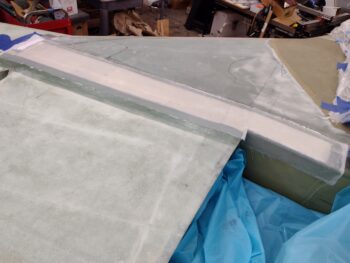
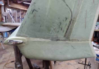
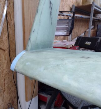
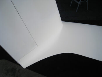
And grabbed a couple lower angle shots… this is a huge improvement on this intersection.  I like how the transition flows nicely and isn’t an unsightly blight when looking at the bird now.

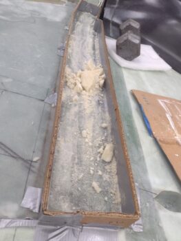
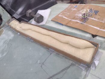
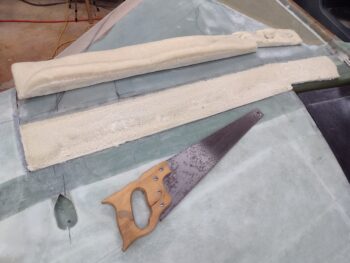
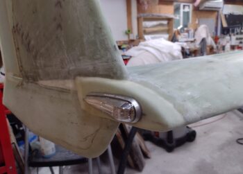
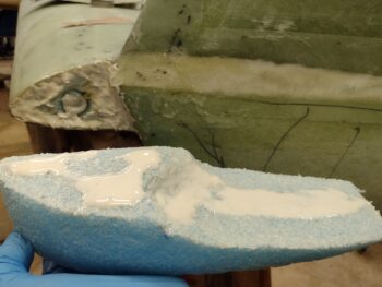
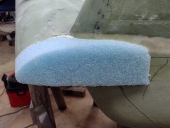
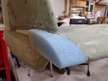
While the left side strake glass cured, I then repeated the process on the right side.  First I sanded down the added foam to shape it.

Another low angle shot pre-glass.

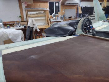
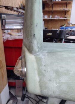
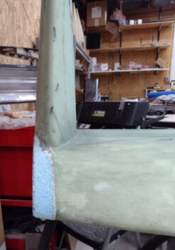
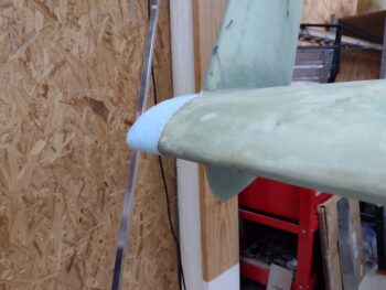
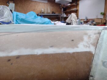
And here we have the right side wing-to-strake intersection & CS spar trough foam fill glassed with a ply of UNI and a ply of BID, with the layup peel plied.

Of course the layup on the right side went considerably faster than the first one so it wasn’t too gawdawful late when I made it back into the house.

With this prerequisite task out of the way, I can now start the installation of the top cowling!

Moving forward.


Chapter 25 – Wing-Strake Intersection

I actually went flying with my buddy Clark for most of the afternoon, so I got into the shop a little late.

I started off by filling the gap between the wing and the CS spar/strake with urethane foam on each side of the plane, and then covered the foam strips with duct tape.

I should note that before I proceeded with any dam-building, pour-foaming or wing-to-strake-intersection-glassing tasks, which to be clear is all a prerequisite to mounting the upper cowling, I took a good 10 minutes each side to note, mark, measure and annotate the positions of my strake storage compartments.

I then constructed a dam for pour foam over the left CS spar using cardboard and duct tape.

After completing the dam, I whipped up some pour foam and poured it into the dam.  Unfortunately, my first round of pour foam —that I stirred for about 70 seconds— was NO GOOD.

As I tested some of the foam left in the cup, I could tell it just wasn’t right… it was too crunchy and didn’t have any “spring” to it.  Moreover, I could really tell it wasn’t a good batch because it came off without a whole lot of effort and merely crumbled into powder.

I tested out a small batch by stirring the old pour foam for well over 100 seconds, and that did the trick.

With my test successful (apparently old pour foam needs a bit more stirring to get the 2 parts to react correctly) I went for another attempt at getting good pour foam into the left CS spar dam.

About 20 minutes later I removed the cardboard dam to reveal a nice loaf of bread… er, uh, a nice batch of pour foam!

I’m either efficient or lazy, but for the right CS spar I re-used the dam I used on the left side by simply flipping it over and reapplying tape.

I did 3 rounds of pour foam on each side, and as I waited about 10-15 minutes each round to ensure the pour was good, I started cutting the glass for the layups I plan on doing tomorrow.

I’ll note that I’m going to kill 2 birds with one stone by not only laying up over the (shaped) pour foam area, but also bridge the gap between the wing and the CS spar/strake (after I remove the wings I’ll add more glass on both the wings and CS spar to secure each half of the transition bridge on the underside of the flanges).

Here we have the right CS spar covered with pour foam that’s contained within the dam.

After I finished cutting the glass, I then pulled the dam off the right side CS spar pour foam fill.

I then grabbed my wood saw and hacked the top off the left CS spar pour foam fill.

And then did the same thing on the right CS spar.

There was still some snack, crackle, pops going on with the foam, so I’ll let it percolate overnight and shape the pour foam applications with my sanding board tomorrow.

Moreover, it was quite late and I am ready to pack it in for the evening.  I’ll continue this task in the morning.


Chapter 20/22 – Nav lights installed

I started off this morning by knife trimming the wire routing hole that leads to the wing cable conduit on the outboard face of the extended & freshly glassed left wingtip.

I then drilled and cleared out the Saran wrap in the three #6 screw holes that allowed me to mount the AeroLEDs Pulsar Nav/Strobe Light mounting bracket.

I then mounted the wingtip Nav light to check out how it looks… Personally, I love it!

Side and angled shots of the left wingtip nav light.

And a straight on shot of the left wingtip nav/strobe light.

I then repeated the same thing on the right wingtip.  I’ll note that on each wingtip extension I spent a good 20 minutes on each side sanding and cleaning up the general area surfaces in prep for the upcoming micro finishing.

Here we have the wire access hole reopened and the nav light mounting bracket screwed in place.

I then mounted the right wingtip nav/strobe light as you can see in these pics here.

And a shot from an aft angle.

And the requisite head-on shot of the right wingtip nav light.

I then rolled into the assessment of my differing height elevations between the front of each respective wing where it meets the aft end of the CS spar/strake.

When I constructed my CS spar I followed the guidance of one of the old guard builders (who worked with/for Burt) that told me to shave a bit off the bottom & top of the CS spar at the outboard end to ensure it didn’t peek up above (or below) the wing… as in the end of the spar being thicker than the wing at that junction.  This is to prevent having to pile on more micro either on the top, bottom, or both sides of the wing.  Not a huge deal in the grand scheme of things, but it does save frustration and moreover, weight, if faced with that issue (apparently enough builders in the day were).

It wasn’t bad advice because even with the reduced thickness of my CS spar outboard end, I can see where even now it’s close to the thickness of the wing.  However, as per usual in any mod we make, the toll must be payed to the induced law of unintended consequences… meaning the reduced thickness carried through somewhat down my spar… more so on the aft side.

Combine that with my intentionally getting anal on ensuring all corners of the wings matched the W.L.’s annotated in the plans, combined with my unintentional oops of setting the reference W.L. at 17.5 vs the plans 17.4 . . .
[again, not on purpose… I measured from the aft side of the spar where the spar cap dips about 0.07″ downward going aft vs the the front of the spar where it is level foam under the glass.  This translated into a reference line closer to 17.5 vs 17.4 — which I of course didn’t catch until AFTER I mounted the wings and drilled all the wing bolt holes!]
. . .  resulting in my wings setting about 0.1″ higher on my CS spar than they should be.  If I had been a bit less anal and a lot more lazy, and strapped my wings to the CS spar so that they were even on both sides it would have resulted in a lot less work now!  And of course most likely naturally much closer to the 17.4 W.L.

{sigh} I will say I think my wings are pretty darn straight [knock on wood!] and evenly mounted on the bird.  When all is said and done they will look spot on… I just have to currently add a bit of filler to the aft end of the CS spar.

I’m about 1/8″ low on the left side, as you can see with the 1/8″ aluminum bar above.  And I’m about 3/16″ low on average on the right side.  This also has to do with the height of the “ridge” of flox and glassed joint where the top strake skin is attached to the front top corner of the CS spar…. obviously about 5-6″ forward of the aft spar edge.  That spar/top skin joint ridge is a hair higher on the right side and is translating over into the increased measured depth of the required fill.

I was thinking of simply micro’ing on a piece of thinly cut foam, BUT because of how the thick spar cap UNI tape has little ridges at the end of every decreasing length, it creates minor dips and peaks on the spar cap area (at least on my bird).  Yes micro is light, but epoxy ain’t so much… so instead of trying to fill all these inherent voids with micro, I decided to go with pour foam.  I don’t care for a good amount of pour foam where it gets hit with constant sunlight, but this application will be thin and covered by a couple plies of glass —and painted white.

Thus, this is my current plan.

Finally, just a fun FYI: as I was measuring, assessing and planning my CS spar-to-wing shenanigans, I grabbed a shot of the left fuel tank pressure test blue glove… still inflated 2+ days later.  I’d say we’re good on the left fuel and thigh support sump tanks.

I’ll note that I also spent a good half hour reviewing my notes and pondering the winglet-to-wing intersection fairing before doing a physical on-site assessment.

In addition, I’ll be discussing my revised plan for the exhaust pipes in the next day or two as well.

Pressing forward.

Chapter 20 – Wingtips glassed

As I pondered more on the cowlings and the exhaust pipes, I went ahead and engaged in the sideline gig today of knocking out the wingtip extension glassing —replete with internal nav light mounting backplate— for both the left and right wings.

I started by finalizing the shaping of each blue foam wingtip, in part “squaring” them up to ensure the outer face was vertical and parallel to the A/C centerline.  This obviously puts the wingtip’s outer face at a different angle than the outboard surface of the upper & lower winglets.

I then marked a reference line that was essentially the chord of each wing… which for us would be W.L. 17.4.   I started on the right wingtip by determining a good location for the nav/strobe light given it is a bit thick in height so it needed to come aft a bit (about an extra 1/4″) from where the original wire channel is so that the darn thing will fit on the wingtip.

The front of the light is about 2.25″ from the LE, so that puts the front edge of the blue foam wingtip addition’s wire channel at 2.5″ aft of the LE, versus 2″ on the original wingtip.

After getting fore & aft figured out on the nav light plate, I then simply center the front of the nav light on the wingtip center of mass, with the same amount of wingtip above and below the edges of the light.

The aft side the light was pointed along a line that was close to parallel to the wing chord, but at the same offset as the front of the light that needed to be centered.  It turns out this is about 0.32″ or 5/16″.

I then removed about 0.04″ of foam so that the backplate surface would sit flush with the outboard face of the wingtip foam extension.

I then plugged the nutplate holes with Saran wrap and micro’d the nav light mounting backplate into place.  I thickened up the extra micro and applied it in various spots to let it all firm up a bit before laying up the 2 plies of BID, as per plans.

As you can see, to keep the backplate firmly in place I screwed a wood block to the wall and used it to keep my spreader clamp from slipping off the wall.

As the right wingtip’s micro’d-in-place nav light mounting backplate cured a bit, along with the added thick micro areas, I then took my rudimentary brown paper template I had made up and used it to cut 2 plies of BID from a large scrap piece.

I prepregged the 2 plies of BID and wetted them out as I applied wet micro to the remaining blue foam of the wingtip extension.  I then laid up the prepregged 2 plies of BID on the right wingtip.

And then of course peel plied the layup.

With the blue foam wingtip extension, where it gets thin as it goes aft it gets crusty and brittle and breaks apart more easily.  I chipped all that away until I had solid foam and then just sanded it down and added a thick micro transition.  I’ll sand this down and simply use micro during the finishing process to finalize the smooth transition all around the wingtip extension, but especially on this aft edge.

As you can see, I went with more of a traditional wingtip extension (‘ol skool?) where the outboard side of the winglet LE, for a good 4+ inches, sits on and transitions with the “wing” as it now appears with this extension.  I did it this way to maintain both the vertical and horizontal components of each axis of the wingtip in keeping them parallel to the A/C centerline, and thus have a bit more of the nav/strobe light visible from the aft side.

A lot of my building buddies shaped this area so that only the inboard curve of the winglet appears on the wing top and the wing “ends” at the centerline of the winglet’s LE.  That method looks awesome and is very clean looking, but it does require more of an angled mount for the nav light as the curve of the outboard winglet is carried forward so that the added wingtip extension front edge terminates very close (virtually nil) to the original wing LE when looking at it from above (vs my constant width extension).

Clearly there is no major safety or aerodynamic advantage one way or the other (that I’m aware of) and it is all just mainly stylistic preference.

I then started on the left wingtip.

Here you can see more of the aft side foam —where it transitions into the winglet— is removed simply because I was mainly getting rid of foam that was breaking away at the thin points.  I was also maintaining the vertical (parallel to vertical A/C CL) outboard wingtip face and this is in part due to that shaping as well.

Note that I had to create my wiring “conduit” hole at an angle going forward to the original wing wire channel… to allow enough meat on the front side of the hole when emplacing the nav light mounting backplate.

Since I didn’t have a solid surface to attach a spreader clamp, on the left side I simply used a long scrap of wood and a bunch of duct tape to secure the micro’d nav light mounting backplate into the blue foam wingtip extension.

Here we have the nav light mounting backplate micro’d into the blue foam wingtip extension, as well as all the foam micro’d and surrounding glass surfaces wet with epoxy in prep for the 2-ply BID layup.

I used the same paper template for cutting out the 2 plies of BID as I did on the right wing (only off the big roll this time) and I also again prepregged the BID plies.

After laying up the left wingtip extension I then again added peel ply.

Another view of the glassed and peel plied left wingtip extension.

As the left side layup cured, I then pulled the peel ply from the right wingtip and cut away the glass over the wire channel in the embedded nav/strobe light mounting backplate.

A parting shot of the glassed (aka FINISHED!) right wingtip.

Time for a glass of red and a late dinner!

Chapter 20-23 – Threading the Needle

Late last night when I got home from a quick late dinner with Jess, I was annoyed that the previously inflated blue glove for my right fuel tank pressure test was totally flat. On a whim I blew in the tube again and set the right fuel tank pressure to about 100 knots on the air speed indicator, and had a decent inflation in the blue glove.  I then closed up shop and went to bed.

Well, this morning, having forgotten about it to some degree, when I went out to the shop 11 hours later I was pleasantly surprised that glove was still inflated nicely.  I then snapped this shot at 15 hours later, as you can see.  For some reason the glove stayed inflated this time around, and I’ll take it!

Of course the ASI read 0 and I suspect it might be part of the problem as it allows for a slow leak.  I will most likely do another round of pressure leak tests before finishing the top strakes, and also after the gas caps are in… only with Freon to ensure there are really no significant leaks.

In more good news, I received the invoice from E-Mag Air and paid them for shipping to send the PMag back.  In the next 2-3 weeks I’ll most likely have the engine back off the bird, and then will re-install the PMag back into its spot.  While the PMag is off the engine I will make a cooling shroud for it as well.

As for the exhaust pipes: I’m done trimming the pipes for now.  I ordered some ER347 filler rod for 321 stainless and plan on tack welding the pipe(s)… first the inboard pipe, and then the outboard pipe to nest as close as possible to the inboard pipe.  I may not actually tack weld the outboard pipe, but will clock it and mark it for James to weld it up.

I then taped a 1″ piece of foam on the top of the flywheel as a gap for the top cowling.  I want to check the exhaust pipes’ elevation with the top cowling in place since I don’t want to end up with the pipes too high in relation to the top cowling.

The title of this blog, “threading the needle” is in reference to the aft opening of my cowlings and the exhaust pipes’ exit out of them.  I may have the narrowest cowling exit on record for a Long-EZ!  I will also note that there is a decent probability that I will be modifying the exhaust pipes even more since they will most likely need to be angled more inboard towards the prop hub.  About one pipe diameter inboard as to where they are now… the outboard slit (aka cowl opening) will be very tight with only about 1/2″ clearance above and below each pipe.

Since the right exhaust pipes come inboard more anyway, they are not quite as bad as the left pipes.

As I did some research, I noted on my buddy Dave Berenholtz’s site that his lower cowling is about 1″ lower than mine at the very aft end if you measured his fin vs mine.  Since I had my bird inverted at the time, I made a decision to mount the cowling to keep the flips minimal.  My lower cowling install seemed much easier than Dave’s because he had the aft opening locked in at a good gap and the bottom cowl’s forward firewall vertical interface parallel to the firewall.

Without an engine installed and inverted, my focus was on the perimeter fit, which resulted in just a hair trimmed off each side and a slight gap towards the bottom between the firewall and the cowling front edge, which again was slanted a bit… requiring me to bridge that bottom gap between cowl bottom edge/front face and firewall.

Conversely, Dave seemed to really fight the bottom cowling sides the entire way and that was because if the sides of the bottom cowling were set in their “natural” state (as I did), that would equate to what I have now: the bottom cowling aft end about an inch higher than it should be.  This helps explain all the significant clearance issues I’ve had.

I’ll note that ONCE I walk the razor’s edge and get the exhaust pipes positioned, and the upper and lower cowlings are in place, that reduced cross-section exposure on my bottom cowling as its angled up more sharply should prove helpful in more unhindered air flow to the prop… we’ll see!

My next task was installing the three #6 nutplates on each nav light mounting backplate.  In addition I terminated a black ground wire and attached it to the backplate for each one as well.  These nav/strobe light mounting backplates are now ready to be installed into the wingtips and covered with a couple plies of BID.

After the “15 hour” pic I took above, I then swapped my test kit over to perform a pressure check on the left fuel tank and thigh support tank.  I took extra measures to temporarily seal the thigh support top port cover, and I think it showed as I had far less leakage on the left tank than the right… at least in these tests.

Here’s clearly a pic at 6 hours later.  I’m calling the left fuel and sump tanks good with virtually no deflation of the glove.  Still, I’ll leave it overnight and see how it looks in the morning.

Since I trimmed my lower winglets down to about 2/3rds the size of the stock plans size —off the top of the foam core, not the bottom— they not surprisingly caused a bit more of a headache going on than the stock sized ones would have.

Why? Because by trimming off the top I reduced the overall width of the lower winglet mounting point a good bit… making them more difficult to align properly going on.  I attempted to focus on the trailing edge and align it straight with the rudder, but in doing so angled the bottom winglets out by about 1/8″ more than they should have been, all things being perfect (are they ever?!).

This slight “kick-out” didn’t manifest itself really until the wings were mounted and the plane upright.  Then you could see the bottom winglet a bit fatter than then top on the outboard side.  I used a straight edge to determine where the offending bulge was and marked it up… it had to be reduced to eliminate a need for extra micro to hide the bump and straighten up this slight difference between the two surfaces.

I grabbed my belt sander and went to town… it didn’t matter to me if I broke into foam, I needed to reduce this profile down significantly.

Surprisingly, I went 3 good rounds with the belt sander, rechecked and remarked the the surface protrusion each time, and then hit the areas again hard with 2 sessions of my 36 grit sanding board… and only on about 1 square inch on the right side did I hit foam.  I’ll patch that and assess this more when I get to finishing the winglets.  This bit of sanding did slim it down noticeably (see pic 2 below).

See the yellow string in the pics above and below?  I used that for my 90° perpendicular line to A/C centerline to then use a big square to mark the cut lines on the foam wingtip additions.  The resulting cut lines are pretty much parallel with the A/C centerline.

I then used a wood saw to cut the blue foam wingtip additions just outside the line.

I grabbed my sanding blocks to then sand the blue foam away just up to the cut line.

I did the same thing on the right wingtip… here are the pair of them shown together.

And a solo pic of the trimmed & sanded right wingtip.  Not bad.

Another shot of the trimmed/sanded right wingtip.  I like the way this looks, but I’ll admit that my biggest headscratcher now is how I’ll work the transition on the bottom winglet with this addition.

I’ll sleep on it and see if any ideas come to mind tomorrow.

I previously mentioned “perfection” and once again curiosity got the best of me.  I measured from the top aft winglet tip on each side to the front centerline of the nose.  Here are the results:
Right ↔ 266-3/4″
Left ↔ 266-5/8″
1/8″ difference for that entire distance?!  I’ll take it!!

Ok folks, calling it a night!

Chapter 20/21/22 – Lights ‘n leaks

Since a fuel tank pressure leak test typically is performed over a 24-hour period [although on further review I’ll note the plans state “several hours”], I wanted to get one going on the right fuel tank as quickly as possible and move on with other stuff.  I did spend a good hour cleaning off the wings and strakes which have been perfect long-term storage areas (ha!) but want things looking presentable since I want to do a video on this subject.  Something I’ve never seen.

Starting off, my plan to focus on only the fuel tanks for the pressure leak test was not going to happen.

In my mind I was going to cap off the GIB thigh support sump tank 1/2″ fuel inlet and 3/16″ vent line —both coming in from the main fuel tank— in the top outboard corner of each sump tank.  However, I failed to remember that I didn’t leave anything but a slight nub showing on these tubes entering into the sump tank.  And unless I had a very tiny stopper for the vent line AND could fumble around up in that corner to get it into place, I wasn’t confident the pressure wouldn’t just pop it out without tape or something securing it (focus inside the square mirror).

The scope of the Fuel Tank Pressure Leak Test now just became the Fuel Tank & Thigh Support Sump Tank Pressure Leak Test.  The only feasible solution without killing a bunch of valuable time was to put the lid back on the thigh support and hope that it doesn’t leak. I didn’t want to use any sealing goop (along with the gasket) because I’m not ready to go final just yet with the sump tanks.

In prep for the test I also pulled the protective plastic 1/8-NPT plug in the fuel drain and put in a Teflon-taped aluminum seal.

I’m using the same 0-15 PSI gauge device that Ary Glantz used when he tested his tanks, and I used a bicycle air pump to slowly pressurize the tank.

Although the tank gauge quickly fell back to zero, the glove was inflated so I went ahead and proceeded with simply watching the glove.  I could tell I had a very small leak with a minute amount of bubbling during my soapy water test at the very bottom edge of the thigh support cap [the pointer stick in pic above is pointing to area of initial bubbling during soapy water application].

The glove stayed inflated for about 2.5 hours but then was clearly well on its way to going deflated when I pulled the first test setup apart.

Test #2 was more old skool, but I was still keeping watching on the thigh support hatch cover.  I’m not sure if the water from my soapy water test had made the gasket act like a sponge, but I was getting zero bubbles after I tightened the screws up a bit more.

So I decided to go for another full test on round 2.  As you can see, this time I used an airspeed indicator and following Waiter’s instructions on IFlyEZ.com.  I filled the tank manually until 100 knots was indicating.

Over the first 10 minutes the ASI slowly dropped to about 90 knots, but then held that for about an hour.  Then over the next few hours it very slowly dropped.  I know that both the 0-15 gauge and ASIs lose air through slow leaks (as per Ary’s discovery) and so my main focus was the inflated blue glove.

Here’s the glove around 4 hours later.  By around 7 hours later it was essentially flat again.  Now, the shop did cool by around 3.5° F, but I feel that I have a very slow leak somewhere… and having literally doused every part of the system with soapy water. I’m not entirely unconvinced (having had soapy water in these tanks for multiple days without losing a drop) that it’s not something in my test setup.

That being said, over the next day or 3 I plan on A) testing the Left fuel tank/thigh support tank using these “standard” methods to see what I find, and B) most likely go with the “nuclear option” and employ Freon for testing for leaks.

After my initial fuel tank pressure testing was underway, I got busy machining a pair of mounting backplates for the AeroLEDs Pulsar nav/strobe wingtip lights.

I started by cutting out a 1.8″ x 5.4″ coupon of 0.04″ 6061 aluminum and secured it for machining with my new favorite method (and now tried and true!) of blue tape and super glue.

I then milled the left nav/strobe light mounting backplate…

And here it is about 10 minutes later…

It took me longer to clean it up than it did to machine the darn thing!

And a test fit for the external Pulsar nav light mount… like butta!

At this point I actually messed around a bit with the fuel tank pressure test, and also was using some OLD Alodine (again, that curiosity thing!) on the left nav light mounting backplate.

I then sliced another 1.8″ x 5.4″ coupon off the ‘ol sheet of 0.04″ thick 6061 and mounted it with blue tape and super glue as well.  Here I’m probing the corner of the sheet to set 0-0-0 for the X, Y and Z axes.

And then machined the right nav light mounting backplate as well.

And here it is… the right wingtip nav/strobe light mounting backplate, hot off the press!

I cleaned it up and also did a fit check with the Pulsar external mounting bracket.  Note the extra countersunk screw just above the front large hole: that is for an “airframe” (aka this mounting backplate) ground wire.

And here we have the pair of mounting backplates for the AeroLEDs Pulsar nav/strobe wingtip lights.  You’ll have to forgive the rather psychedelic appearance of these backplates given, again, that the Alodine I used was rather OLD!  Thank goodness these things will get buried in the wingtips eh?! <smile>

And with that, I called it a night!

Chapter 21/23 – Pipes & Wingtips

Curiosity got the best of me and I wanted to get some epoxy curing in some form or fashion on this bird, so I spent about 10 minutes shaping the blue foam wingtip cap for the left wing. Yesterday I rummaged around and found good foam scrap candidates for each wing tip, and today I’m getting at least one of them secured in place.

After cleaning some of the old dead micro and epoxy off the exposed foam at the leading edge area wingtip, I then slathered up both sides with micro.

After getting the foam in pert near the exact desired position, I taped the crap out of it to ensure it didn’t move and was pressed up tight against the wing tip and forward “corner” of the winglet (at the pointy junction where top and bottom winglets meet).

After my approximate half-hour diversionary task was complete, I jumped back on the left inboard exhaust pipe.  I cut the first wedge I had marked up from last night, set up the inboard in position again to mark round 2 of trimming.

Which is shown prepped here.  I then cut this slant wedge off as well.

After my first two rounds of trimming the intersection angle of the left inboard exhaust pipe, I then gave my exhaust pipe welding bubba, James, a call.  He let me know that he had 3 race car exhaust header sets he had to get out the door this week, but that next week he only had one… given that next week was looking like a light week for him, we scheduled my exhaust pipe weld-ups for then.  That schedule actually works out perfectly for me since I can get a jig built for the right side pipes to have James heat those up and bend them just a skooch (~1/4″) up.

With that, I finished round 3 of trimming the left inboard pipe intersection angle.

Since I now had some breathing room, I shaped the blue foam wingtip extension for the right wing and micro’d it in place as well.  And yes, I slathered it with duct tape again (which isn’t adhering so well… thus the added securing plies) to keep it in place tightly and securely.

By this point the left side wingtip foam addition micro had cured so I pulled the tape.  Looking good so far!

I then sanded the added blue foam block parallel to the surface of the wing… not bad!

Here’s another couple shots of the blue foam wingtip add-on shaped to match the left wing contour.  I’ll of course work the actual end shape A) after I decide exactly what style I want, and B) as I have time in-between the engine and cowling stuff.

I then took a break to grab a late lunch and finish my latest research (technically RE-research) on fuel tank leak testing.  I refreshed my knowledge base by looking at the plans, reading the CP newsletters, searching through the CSA articles, and looking at various canard build websites.

I decided for ease of getting the fuel tank pressure/leak testing done I would simply copy another smart guy builder, Ary Glantz, in his approach.  He used a small 0-15 psi gauge with an included schrader valve (for a standard bicycle tire pump) to pressurize his tank.  Moreover, they sell these gauges at Home Depot… the biggest problem being the closest Home Depot to me is 45 minutes away.

I tried to call Jess but she wasn’t available at that point.  10 minutes later I was back out in shop evaluating the left inboard exhaust pipe and marking it up for yet another round of trimming the intersection angle when she called me back.  I asked if she was up for having dinner in Jacksonville and doing some shopping while I wondered around Home Depot looking for all my tube fittings to cobble together a fuel tank pressure test kit.

An hour or so later we were having dinner and planning out our respective shopping adventures!

Upon returning back home with my new bag of goodies, I went back out to the shop for a bit to remove all the tape from the right wingtip new blue foam addition.  I then grabbed my sanding board and shaped the blue foam parallel to the wing curvature, just as I did on the left side.

Here are a couple more shots of the right wingtip foam extension from a lower angle.

I then closed up the shop and headed back into the house.  I had retrieved my box of AeroLEDs Pulsar Nav/Strobe lights earlier and I pulled the instructions out.  In the included instruction sheet is a template for the nav/strobe light mounting backplate.  However, the instruction sheet template is not to scale, and although they tell you how to print it out so that it is to scale, I simply spent 10-15 minutes modeling it up in F360 CAD.

I then 3D printed a test 0.020″ thick backplate to ensure it was correct and to scale, and Voila!  It was.

Within the next week I intend to construct the wingtip nav/strobe light mounting backplates out of 0.04″ thick 6061 aluminum… I’ll machine them so they are clean and to nice tight tolerances.

And with that, I called it a night.

Chapter 23 – Final pipe shape?

I had a lot going on starting out today, and most of it wasn’t in the shop until mid-afternoon rolled around.  Late last night and first thing today, I reviewed my initial plans for pressure testing the fuel tanks for leaks.  No, I haven’t done that yet and before I move into adding more glass and micro to the tanks, I want the leak tests completed.

I’ll remind everyone that between my old hangar getting hit by a tornado, and thus destroying a lot of my historical note binders with water and wind, combined with Windows 7 no longer being supported so my instant access to One-Notes ended (I can go through a painful, convoluted process to get them… and some I’ve retrieved).  After these two events, my “instant info” access & retrieval was hampered greatly.

I note the above to explain why I spent a good half hour going through all my emails in performing some engine baffle data collection and consolidating pics, etc. into a PowerPoint presentation.  Yep, engine baffles are looming on the horizon!

In addition… since I haven’t capped the end of my wings or made provisions to mount the nav/strobe lights yet, I did a bit of the same data collection thing.  Only this time reviewing pics online and my own site in a somewhat impromptu design review.  I had a number of pics of my buddy Marco’s wingtips for his bird JT, but didn’t have any I could find for Mike Beasley’s “Scooter”… I texted Mike and thankfully he was at his hangar so within short order I had over a half dozen pics of his wing tip/nav light/winglet interface.  I’ll note I also did a good once over of Dave Berenholtz’s site as well, and hit up fellow builder Brian Ashton in Alaska for what he had for his configuration.

I then got out to the shop.

The first thing I did was set up my welding station: got the TIG welder all set up and plugged in, and then test welded some scraps of this 321 stainless steel pipe.  As per Clinton at Custom Aircraft Parts, 321 SS requires ER347 filler rod and I don’t have any on hand… nor does any welding shop in Eastern Carolina! (actually within an hour of me…).  Moreover, the cost of getting it shipped to me here within the next week wouldn’t be worth the money (not even Amazon has a vendor that can ship it within 2-3 days).

This 347 welding rod is important since my test runs at tack welding such thin-walled pipe was not working and serving only to melt the edges of the pipe segments being joined, no matter what amp setting I was using.

Thus I decided that I would simply mark the pipe configurations and take all the pieces to James and have him weld them up from individual pieces.

With my 321 stainless steel exhaust pipe welding stint cut tragically short, I proceeded to pick up where I left off last night in shaping the intersection of the new straight segment on the left inboard pipe.  After the initial slant cut to interface it with the 90° elbow of the slip joint mount tube, I realized that my 2.2″ extension piece of pipe was just a hair short and wasn’t going to pass muster.

I grabbed the outboard pipe, marked off 2.75″ inches (it came out to 2.7″ after cutting), taped the cut line and trimmed it down.

I then added the 2.7″ extension to the inboard pipe and prepped it for shaping to intersect (again) the 90° elbow of the slip joint mount tube.  It was early evening at this point and I had told Jess, who unexpectedly had the evening off, that we could go out for a bit and enjoy a “cool” mid-80’s (vs the recent mid-90s) evening.  Thus again, this task will be continued tomorrow.

I’ll add that I forgot to post this yesterday: the newly arrived brass 1/2-NPT 45° street elbow for the bottom engine sump oil heat OUT hose… to replace the current steel 90° one that is just way too big and reeking havoc with its zero clearance with the SCEET tubing.  Just as with the sniffle valve, I’m hoping a switch to a 45° street elbow will solve my clearance issues.

Again, I am seriously hoping and cautiously optimistic that my exhaust pipe clearance issues will be resolved soon!

Chapter 23 – Left pipes a tweakn’

Today I continued on in my quest to get the exhaust pipes tweaked to fit inside the cowling… and still working specifically the left side at this point.

Before I could continue on with finalizing the configuration of the left side exhaust pipes, I needed to check the clearance between the spark plug in cylinder #1 with cylinder #3’s exhaust pipe.

I had Champion aircraft spark plugs installed but after a good bit of research during the past year I learned that Autolite 386 plugs are good to use with the PMag, so I picked a few up.  Now I need to install them in the bottom plug holes in each cylinder to test out clearance with both the actual plugs I’ll be using and the PMag spark plug cables.

Now, not only are these Autolite 386 spark plugs 18mm [read: no adapter] and run well (according to a bunch of RV drivers… but can we trust them?? ha!), but they are pretty darn cheap to boot.  That means I will be changing them out at every annual… which is where this exhaust pipe story has even yet another twist….

You see, I thought the tight cowling was causing all the issues, but interestingly enough when I went to remove the aircraft plugs on the right side, I couldn’t even get the socket over the plugs due to the exhaust spring tabs and springs being in the way.  With some judicious bending of the forward cylinder’s exhaust tab I could force the socket on there and got the A/C plug removed.  And yes, the Autolite plug was easier going in.

However, on the aft cylinder I had to remove the exhaust pipe completely to get my socket onto the A/C spark plug to remove it.  I had a decent bit of oil oozing out of these cylinders, so I wasn’t mindful of replacing the aft cylinder exhaust pipe first to test out if the Autolite would have gone in easier than the A/C plug coming out.

I then took a few minutes to connect the PMag spark plug cables up to each respective plug and run all the cables forward to the front of the engine.

Ok, back to the exhaust pipes.

I had marked the left outboard exhaust pipe to allow me to secure the pipe to the 90° mounting flange, according to my index mark.  After mounting all the pipes in place I then put the cowling back on.

Here’s the left outboard exhaust close to the configuration where I plan to tack weld it in situ, and then have James finalize the job with a beautiful TIG weld worthy of 321 stainless steel!

I then of course checked the clearance of the installed bottom spark plugs and their associated cables… much better than I had expected and not bad at all (I put green tape on the black spark plug cable boot to make it more visible).

And here’s a shot of the clearance between the left outboard exhaust pipe and lower cowling.  Optimized?  Hell no!!  But good enough for the space I have going on here!  Especially since I’ll be lining the interior cowling with Thermo-Tec to keep it from burning up (as if I had a choice!)… I’ll also most likely get the pipes ceramic coated as well fairly early on to cut radiated heat down as much as possible.

I then turned my attention to the inboard left exhaust pipe.  Here’s the “dip” issue I pointed out yesterday. I used a ruler to show the dip more clearly.

And here’s somewhat the same thing over on the bench… note the dip is very close to 1/4″ deep.   Which is significant in this situation.

Back to the left inboard pipe set in place, here you can see that dip coming down and kissing the bottom cowling.  Now, in reality that pipe is not touching the cowling.  The issue is without a pipe used to lever over the spring loaded slip joint mount, it springs outboard a bit and messes up the mocking up of the pipe… so if it were all put together there would actually be daylight (albeit not much) under that dipped pipe.

I took measurements at the point where the forward curve (that causes the dip) starts on the left inboard exhaust pipe.  I then set it in place and determined as best as I could the length of pipe (after trimming) that I would need to not only connect the pipe back into place, but to also ensure it stays nested with the outboard pipe.

My measurement was close to 1.8″ to remove the dip, so I planned on cutting off a 2.2″ replacement straight segment from the very aft end (which is excess and will get trimmed off all the pipes). The 0.4″ added difference as extra just in case [in retrospect it may still not be enough].  I then marked each cut line at each end with green tape.

I then spent some time with my Dremel and small cut off tool to cut the pipe at the cut lines.  I didn’t spend a lot of time on the green tape end since that will get trimmed to reconnect to the 90° pipe.

I then set it back in place… this isn’t a perfect representation since the added pipe is still a little high, but the low point now will be the 90° elbow and not the dip.

Moreover, with the hole in the cowl from me removing the goiter that was there for the alternator, I plan to expand my fill out a bit wider to add a hair more clearance depth to encompass that area of the low 90° elbow.

Here’s another shot of the left exhaust pipes mocked up in place.  Note how you can now clearly see daylight underneath the majority of the pipes.

Another shot of the left exhaust pipes… I’m going to do my darnedest to keep the pipes nested together to optimize their flow.

Again, although set just a tad high, here is a good representation of the now straight inboard left exhaust pipe… sans dip.  Much better as we can see above regarding clearance with the cowling.

Tomorrow I plan to break out the TIG welder and do some tacking on these pipes.  After I lock in the position of the left outboard exhaust pipe then I’ll configure the inboard pipe and tack it up as well.  Once the left side pipes are actually welded up and in place, then I’ll work the comparatively minor tweaks on the right pipes.


Chapter 23 – Pipes… mind the gap!

Today was all about getting the left exhaust pipes configured in situ.

I started off with the left inboard exhaust pipe and marked its cut line with the green tape.

I then made my initial cut on the left inboard exhaust pipe.

With a 1/2″ spacer in place for minimum clearance you can see the resulting gap between the 2 pipe segments.

I trimmed the forward 90° segment about 1/8″ on the bottom and about 1/4″ off the top. This trimmed 1/8″ on the bottom reduced the depth of the pipe by about 0.070″ (from the very lowest point).  This gives me a minute bit more clearance with the cowling, but I’ll take every bit I can.  The differential amounts removed served to angle the opening up just slightly.

The green tape is the next round of trimming for the aft segment of the left inboard exhaust pipe.  You can see it will bring the joint much more closely aligned…

Although the new cut didn’t make for a perfect connection angle… I’m “walking” these joints in so as to not overshoot the required angles.

[Note the curved “dip” of the first ~2 inches of the aft pipe segment? (right after the cut) Although this rounds out the flow and makes for a nicer curve, it also drops the pipe to the closest point of all the exhaust pipes in relationship to the cowling surface… I’m thinking strongly of removing this curved section and replacing it with a straight segment of the same length]

A bit wider view on the left inboard exhaust pipe.

Although I marked the left outboard exhaust pipe cut line with tape along with the inboard pipe, I didn’t want to convolute the information flow above…  in reality I cut the inboard pipe first, then the outboard pipe, before fine tuning the inboard pipe.

As I was pondering the forward curved 2-inch section of the inboard pipe I mentioned above, I cleaned up the cuts of the outboard exhaust pipe and then mounted the outboard exhaust pipe 90° section.

I then taped the left outboard pipe in place with spacers for elevation and cowling clearance.  After some long pondering on this outboard pipe as well, I decided that I will most likely shape the (currently cut) weld joint to pivot the pipe in a clockwise manner (looking towards nose) to gain a bit more cowling clearance and also more clearance for the #1 cylinder spark plug (the clearance is too close for comfort at this point).

In addition, the aft end of the pipe will have to come up about a 1/4″ higher to facilitate the clearances above.

Here’s a couple shots of the “nested” left side exhaust pipes… definitely an improvement from what they were! (but we can do better….!).

And a look at the right side pipes.

Admittedly, these shots are a hair misleading because the wood spacers are both lifting the longer pipes UP while also pushing the flange of the lower cowling DOWN just a bit.  In reality, these right-side pipes will both most likely need to come up about 1/4 to 3/8″.  The bend, whether an actual bend or cut/reweld will be a few inches aft of the corner of cylinder #2.

And here’s one last shot of both left and right pairs of exhaust pipes in their newly elevated states.  Yes, it’s a work in progress folks!

My plan is to work these exhaust pipe configurations over the weekend and have them done by next Monday/Tuesday.  Then as soon as James has time, I can get these things welded up and get on with the upper cowling install.

I will note that there may be more welding required on the aft ends of the pipes if they need to be turned downwards to be leveled out on a more horizontal plane… just a thought at this point.

Pressing forward!