
Since a fuel tank pressure leak test typically is performed over a 24-hour period [although on further review I’ll note the plans state “several hours”], I wanted to get one going on the right fuel tank as quickly as possible and move on with other stuff. I did spend a good hour cleaning off the wings and strakes which have been perfect long-term storage areas (ha!) but want things looking presentable since I want to do a video on this subject. Something I’ve never seen.
Starting off, my plan to focus on only the fuel tanks for the pressure leak test was not going to happen.
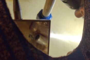
In my mind I was going to cap off the GIB thigh support sump tank 1/2″ fuel inlet and 3/16″ vent line —both coming in from the main fuel tank— in the top outboard corner of each sump tank. However, I failed to remember that I didn’t leave anything but a slight nub showing on these tubes entering into the sump tank. And unless I had a very tiny stopper for the vent line AND could fumble around up in that corner to get it into place, I wasn’t confident the pressure wouldn’t just pop it out without tape or something securing it (focus inside the square mirror).
The scope of the Fuel Tank Pressure Leak Test now just became the Fuel Tank & Thigh Support Sump Tank Pressure Leak Test. The only feasible solution without killing a bunch of valuable time was to put the lid back on the thigh support and hope that it doesn’t leak. I didn’t want to use any sealing goop (along with the gasket) because I’m not ready to go final just yet with the sump tanks.
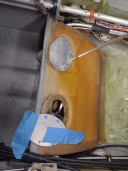
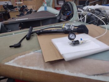
In prep for the test I also pulled the protective plastic 1/8-NPT plug in the fuel drain and put in a Teflon-taped aluminum seal.
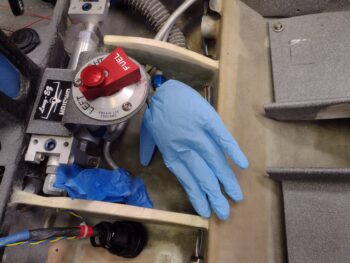
I’m using the same 0-15 PSI gauge device that Ary Glantz used when he tested his tanks, and I used a bicycle air pump to slowly pressurize the tank.
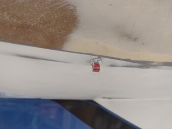
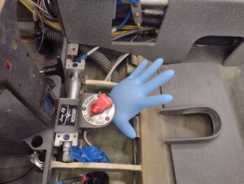
Although the tank gauge quickly fell back to zero, the glove was inflated so I went ahead and proceeded with simply watching the glove. I could tell I had a very small leak with a minute amount of bubbling during my soapy water test at the very bottom edge of the thigh support cap [the pointer stick in pic above is pointing to area of initial bubbling during soapy water application].
The glove stayed inflated for about 2.5 hours but then was clearly well on its way to going deflated when I pulled the first test setup apart.
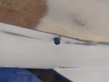
Test #2 was more old skool, but I was still keeping watching on the thigh support hatch cover. I’m not sure if the water from my soapy water test had made the gasket act like a sponge, but I was getting zero bubbles after I tightened the screws up a bit more.
So I decided to go for another full test on round 2. As you can see, this time I used an airspeed indicator and following Waiter’s instructions on IFlyEZ.com. I filled the tank manually until 100 knots was indicating.
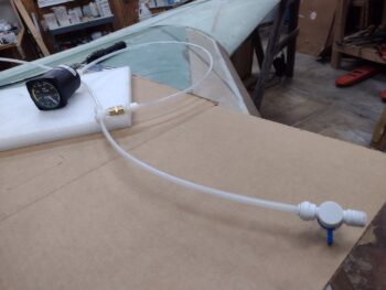
Over the first 10 minutes the ASI slowly dropped to about 90 knots, but then held that for about an hour. Then over the next few hours it very slowly dropped. I know that both the 0-15 gauge and ASIs lose air through slow leaks (as per Ary’s discovery) and so my main focus was the inflated blue glove.
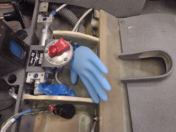
Here’s the glove around 4 hours later. By around 7 hours later it was essentially flat again. Now, the shop did cool by around 3.5° F, but I feel that I have a very slow leak somewhere… and having literally doused every part of the system with soapy water. I’m not entirely unconvinced (having had soapy water in these tanks for multiple days without losing a drop) that it’s not something in my test setup.
That being said, over the next day or 3 I plan on A) testing the Left fuel tank/thigh support tank using these “standard” methods to see what I find, and B) most likely go with the “nuclear option” and employ Freon for testing for leaks.
After my initial fuel tank pressure testing was underway, I got busy machining a pair of mounting backplates for the AeroLEDs Pulsar nav/strobe wingtip lights.
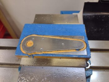
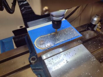
I started by cutting out a 1.8″ x 5.4″ coupon of 0.04″ 6061 aluminum and secured it for machining with my new favorite method (and now tried and true!) of blue tape and super glue.
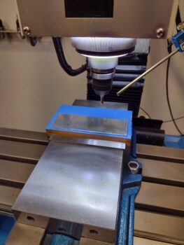
I then milled the left nav/strobe light mounting backplate…
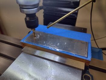
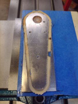
And here it is about 10 minutes later…
It took me longer to clean it up than it did to machine the darn thing!
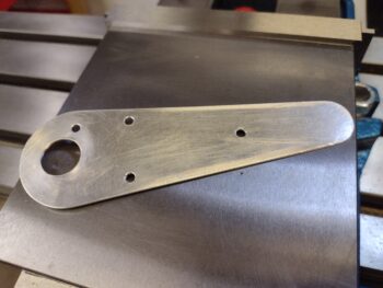
And a test fit for the external Pulsar nav light mount… like butta!
At this point I actually messed around a bit with the fuel tank pressure test, and also was using some OLD Alodine (again, that curiosity thing!) on the left nav light mounting backplate.
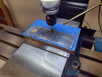
I then sliced another 1.8″ x 5.4″ coupon off the ‘ol sheet of 0.04″ thick 6061 and mounted it with blue tape and super glue as well. Here I’m probing the corner of the sheet to set 0-0-0 for the X, Y and Z axes.
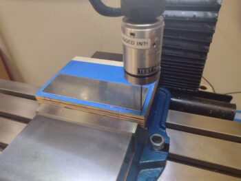
And then machined the right nav light mounting backplate as well.
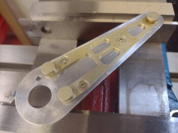
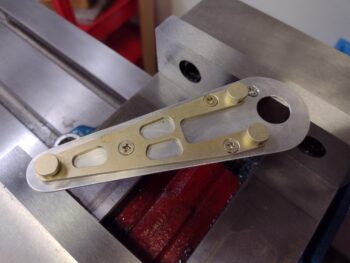
And here it is… the right wingtip nav/strobe light mounting backplate, hot off the press!
I cleaned it up and also did a fit check with the Pulsar external mounting bracket. Note the extra countersunk screw just above the front large hole: that is for an “airframe” (aka this mounting backplate) ground wire.
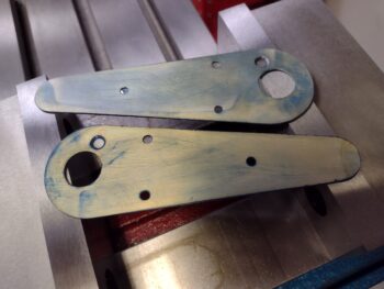
And here we have the pair of mounting backplates for the AeroLEDs Pulsar nav/strobe wingtip lights. You’ll have to forgive the rather psychedelic appearance of these backplates given, again, that the Alodine I used was rather OLD! Thank goodness these things will get buried in the wingtips eh?! <smile>
And with that, I called it a night!