
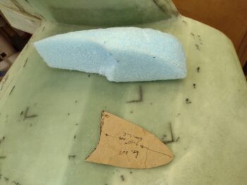
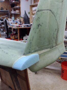
Curiosity got the best of me and I wanted to get some epoxy curing in some form or fashion on this bird, so I spent about 10 minutes shaping the blue foam wingtip cap for the left wing. Yesterday I rummaged around and found good foam scrap candidates for each wing tip, and today I’m getting at least one of them secured in place.
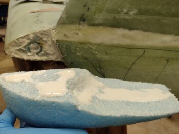
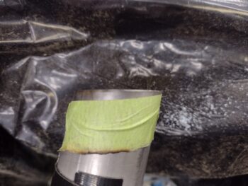
After cleaning some of the old dead micro and epoxy off the exposed foam at the leading edge area wingtip, I then slathered up both sides with micro.
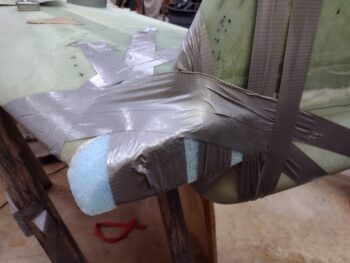
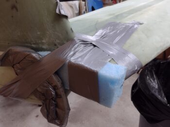
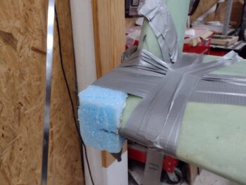
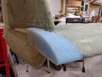
After getting the foam in pert near the exact desired position, I taped the crap out of it to ensure it didn’t move and was pressed up tight against the wing tip and forward “corner” of the winglet (at the pointy junction where top and bottom winglets meet).
After my approximate half-hour diversionary task was complete, I jumped back on the left inboard exhaust pipe. I cut the first wedge I had marked up from last night, set up the inboard in position again to mark round 2 of trimming.
Which is shown prepped here. I then cut this slant wedge off as well.
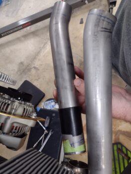
After my first two rounds of trimming the intersection angle of the left inboard exhaust pipe, I then gave my exhaust pipe welding bubba, James, a call. He let me know that he had 3 race car exhaust header sets he had to get out the door this week, but that next week he only had one… given that next week was looking like a light week for him, we scheduled my exhaust pipe weld-ups for then. That schedule actually works out perfectly for me since I can get a jig built for the right side pipes to have James heat those up and bend them just a skooch (~1/4″) up.
With that, I finished round 3 of trimming the left inboard pipe intersection angle.
Since I now had some breathing room, I shaped the blue foam wingtip extension for the right wing and micro’d it in place as well. And yes, I slathered it with duct tape again (which isn’t adhering so well… thus the added securing plies) to keep it in place tightly and securely.
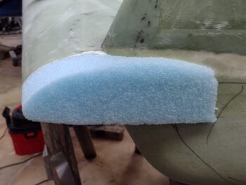
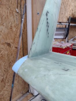
By this point the left side wingtip foam addition micro had cured so I pulled the tape. Looking good so far!
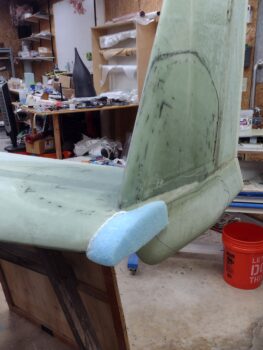
I then sanded the added blue foam block parallel to the surface of the wing… not bad!
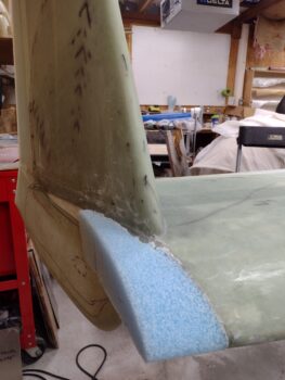
Here’s another couple shots of the blue foam wingtip add-on shaped to match the left wing contour. I’ll of course work the actual end shape A) after I decide exactly what style I want, and B) as I have time in-between the engine and cowling stuff.
I then took a break to grab a late lunch and finish my latest research (technically RE-research) on fuel tank leak testing. I refreshed my knowledge base by looking at the plans, reading the CP newsletters, searching through the CSA articles, and looking at various canard build websites.
I decided for ease of getting the fuel tank pressure/leak testing done I would simply copy another smart guy builder, Ary Glantz, in his approach. He used a small 0-15 psi gauge with an included schrader valve (for a standard bicycle tire pump) to pressurize his tank. Moreover, they sell these gauges at Home Depot… the biggest problem being the closest Home Depot to me is 45 minutes away.
I tried to call Jess but she wasn’t available at that point. 10 minutes later I was back out in shop evaluating the left inboard exhaust pipe and marking it up for yet another round of trimming the intersection angle when she called me back. I asked if she was up for having dinner in Jacksonville and doing some shopping while I wondered around Home Depot looking for all my tube fittings to cobble together a fuel tank pressure test kit.
An hour or so later we were having dinner and planning out our respective shopping adventures!
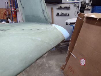
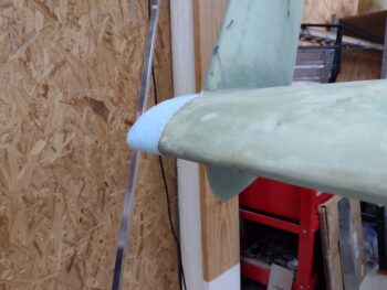
Upon returning back home with my new bag of goodies, I went back out to the shop for a bit to remove all the tape from the right wingtip new blue foam addition. I then grabbed my sanding board and shaped the blue foam parallel to the wing curvature, just as I did on the left side.
Here are a couple more shots of the right wingtip foam extension from a lower angle.
I then closed up the shop and headed back into the house. I had retrieved my box of AeroLEDs Pulsar Nav/Strobe lights earlier and I pulled the instructions out. In the included instruction sheet is a template for the nav/strobe light mounting backplate. However, the instruction sheet template is not to scale, and although they tell you how to print it out so that it is to scale, I simply spent 10-15 minutes modeling it up in F360 CAD.
I then 3D printed a test 0.020″ thick backplate to ensure it was correct and to scale, and Voila! It was.
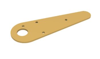
Within the next week I intend to construct the wingtip nav/strobe light mounting backplates out of 0.04″ thick 6061 aluminum… I’ll machine them so they are clean and to nice tight tolerances.
And with that, I called it a night.