Tooling Up: CNC Components

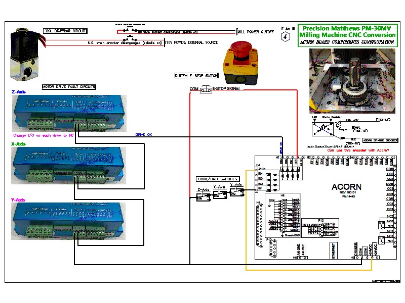
I ordered a 3 Nm (Newton meter)/425 oz-force inch Closed-loop stepper motor kit that included the motor, a drive and a 36V power supply.  I received all but the power supply and after a quick email exchange I have one coming from the seller.  In addition, I bought a data transfer cable (gray) that allows me to reprogram some of the default settings on the drive for better optimization and performance in my CNC setup.  

Shortly after I ordered this 3 Nm closed-loop stepper motor was when I had my epiphany regarding my planned purchase of a Precision Matthews PM-30MV machining mill vs the previously planned PM-25MV.  Now, the PM-25MV typically uses Nema 23 sized motor mounts such as this 3 Nm stepper motor for its X axis and Y axis.  Moreover, the PM-25MV uses a larger Nema 34 stepper motor for the Z axis.  This contrasts somewhat with the PM-30MV which uses the larger Nema 34 mounts for all axes.

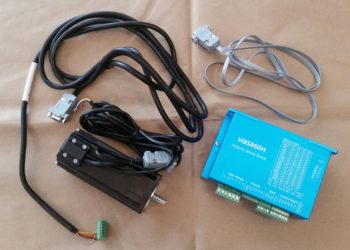
Well, although it’s a bit overkill, my new plan regarding the model of Machining Mill to purchase subsequently pressed the 3 Nm stepper motor into service as the Z axis motor on my upcoming lathe CNC conversion.  The lathe’s X axis will still get the planned 2.2 Nm (311 oz-force in.) closed-loop stepper motor, which is what I had also decided on originally for the Z axis as well.

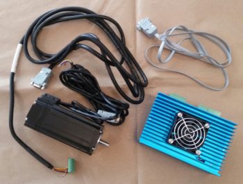
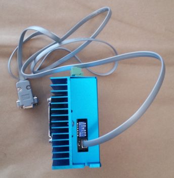
If you’re wondering about the drive data cable (yes, exciting . . . ), here’s a shot of it below with it plugged into the stepper motor drive.  Again, the cable will be hooked up to a computer with Acorn CNC software to change a few distinct operating parameters on the drive before using it for live CNC operations.

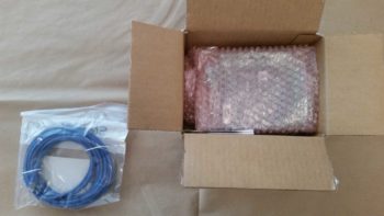
As I mentioned in an earlier post, after a lot of research I decided to go with Centroid Acorn CNC as my CNC controller software and hardware.  Below is a shot of the freshly delivered & opened box of my Centroid Acorn CNC kit.  The blue cable is a specific shielded CAT5 data cable that is called for by Centroid Acorn, and is connected between the controlling computer and Acorn CNC board.

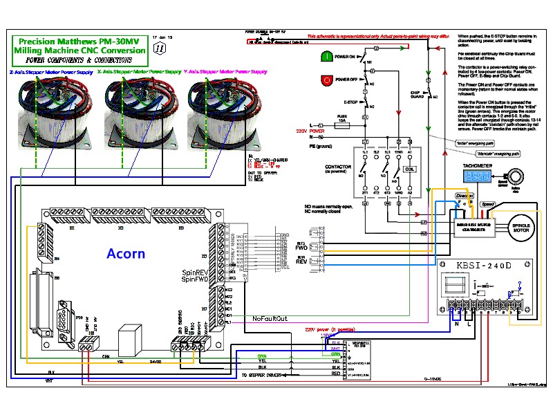
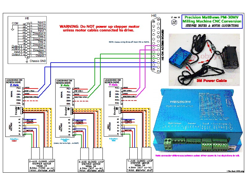
Speaking of the Acorn CNC board, here is a shot of it right here.  If you refer back to my wiring diagrams you’ll see how they depict the many pinout connections to this board.

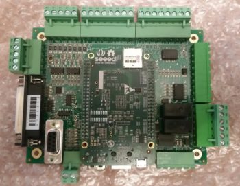
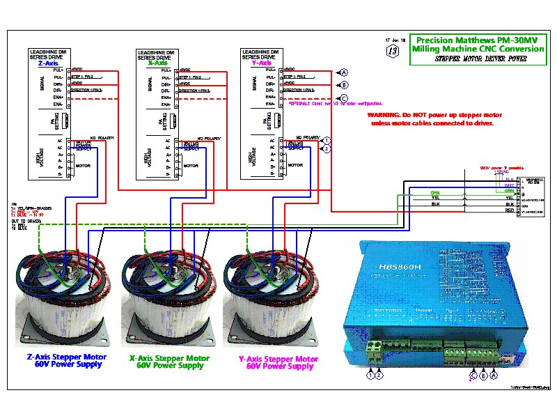
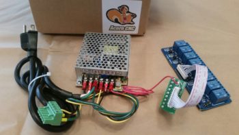
A few of those connections are board and accessory power from the Acorn power supply (shown below) as well as a multi-jack connection to a relay breakout board.  In my setup this relay board will help control the spindle speed and direction to allow for hard thread tapping, among other things.

As you can see, I’m pressing forward with my machining and CNC endeavors…  the plan being to be ready to quickly fire all this up once I move down to North Carolina in order to finish the plane as quickly as possible.

Tooling Up: Fusion 360 CAD

After getting the lion’s share of my machining equipment and CNC conversion requirements, designs, and BOMs knocked out, I decided it was time to sink my teeth into learning some CAD…. specifically, what is arguably the standard CAD package these days: Fusion 360.

After downloading Fusion 360 and getting it running, I then spent a myriad of hours working through countless YouTube videos to start getting the basics down.  I really found Lars Christensen’s channel to be helpful and following his sage tutelage was able to create a CAD drawing of an electrical conduit box, shown below.

With my newfound knowledge, I then set out to create some drawings for the power drawbar that I will construct for my mill.  For an explanation of what a power drawbar does, I’ll defer to the excellent description my buddy Marco provides on his blog.  

I started with a simple piece of the drawbar assembly and was pleased that I was able to knock it out in fairly short order.

I then bit off a much bigger part that would allow me to employ some of my own creative ideas in creating a flat side plate of the pneumatic drawbar and punching triangular shaped holes in it.  It’s my first take on the side plate, and it could easily change, but so far I like what I have.

I then drew up the pneumatic drawbar top plate that has a mounting hole in it for the air cylinder that drives the drawbar levers down to release the Tormach Tooling System (TTS) tool holder.

I then had to put my Fusion 360 creative endeavors on hold for about a week as I ran out to Portland, Oregon to help my Mom with some medical stuff.  In addition, while in Portland I had to work a compatibility issue that cropped up that wouldn’t allow me to run Fusion 360 on my older MacBook Air.  

At first it appeared my only option to use Fusion 360 on the go would be to buy a new laptop, since on the face of it an upgrade to the latest Mac OS (Mojave) would crash my older MacBook.  After a few days of research I then discovered that I could simply upgrade my laptop to the Sierra OS immediately following the one I had installed, El Capitan.  I waited until I got home from Portland to clean and backup my laptop’s hard drive before updating my OS to Sierra.  

Once Sierra was up and running, Voila! my Fusion 360 was also back up and running.

Tooling Up: Future CNC

For a number of years my buddy Marco has helped me out with making stuff in the machining realm, be it metal or plastic . . . on the lathe, mill or 3D printed.  I’ve always greatly appreciated his fantastic work and wonderful help, but also had always planned on learning the magic of machining to facilitate not only creating components for my Long-EZ, but for many other projects as well.

Thus then, another recent segue in my build –stemming from my back injury (all good now) and subsequent house selling delay– was to prep for the upcoming onslaught of machining projects in the hopper that will need to be completed before my bird takes flight.  Yes, admittedly a good number of these required components are the result of self-inflicted mods and stylistic preferences, but regardless all these parts need to be completed for the plane to be completed as well.

The time finally came, as I knew it would, for me to knuckle and buckle down to get serious about my machining abilities, specifically in regards to learning CAD (Fusion 360) and having CNC-capable machines both on a Mill and Lathe (3D printing will follow shortly). Again, with so many components that need to be machined, I could no longer in good conscience ask Marco to take time out of his busy schedule to do the copious amounts of machining required to create my Long-EZ parts (not that he’d have the time to do them all anyway).

Since I had already done a fair amount of research on the CNC equipment side of the house, I decided to start there.  After returning from my holiday sojourns, and with my first scheduled instrument training flight nearly a week away, I decided to nug out the equipment and materials requirements for both my lathe and mill CNC conversions.

Since the mill is higher on the priority list –I do have my lathe on hand– I decided to start with it first.  In addition, since my mill will have 3 axes vs. the lathe’s simple 2 axes, it would be easier to par down the mill’s CNC electrical diagrams to convert them over for lathe CNC diagrams.

After a good 3 days of intense research, emails, phone calls and reading, my plan came to life at which point I captured over 90% of it all in 4 electrical diagrams.  Midway through the process of creating these electrical diagrams, a discussion I had with Marco sparked an epiphany of sorts at which point I decided to upgrade the machining mill I plan to buy from a Precision Matthews PM-25MV to a PM-30MV.  In short, the PM-30MV provides more travel in the X, Y and Z axes, and it has a more powerful 2 HP (vs 1 HP) motor that provides more torque and higher RPMs.  Lastly, the PM-30MV is much heavier, and is thus a more stable, rigid platform for CNC operations.

So without further ado, here is the first of my wiring diagrams for the CNC conversion of my (planned) Precision Matthews PM-30MV Machining Mill.

As you may have noted in the diagram above, I made a final decision on the CNC controller hardware and software with the Centroid Acorn system.  I also decide to “go ugly early” by ordering the first of my closed-loop stepper motors, which are much more expensive than the open-loop stepper motors (most common) but much more capable for CNC.  These closed-loop stepper motors use upgraded (again, in comparison) drives compared to open-loop stepper motors.

This diagram depicts the motor data connections between the Acorn board and drives, and also the data and power connections between each drive and motor.

I then figured out the power circuits for the 5V and 60V power between the Acorn power supply, individual axes drives and axes power supplies.

Finally, I made up a diagram to depict the remaining discreet components that make up the CNC system: power drawbar air valve, the E-Stop switch circuit, spindle speed encoder, drives’ alarm circuit, and home/limit switch connections.