Chapter 23 – Video Update

Today I spent a few hours filming, editing and finishing up a video that I’ve been working on the past few days that I wanted to get out before throwing myself headlong into working on the engine install.

This video covers the Fuel Injection Servo configuration and install, the air induction system and the RAM air can ops, including some footage of the new lever and actuator in action as they manipulate the RAM air can butterfly valve open and closed.

Tomorrow I have a bunch of errands to run, but I do plan on starting back to full time work on the engine install Saturday.

Pressing forward!

Chapter 22/23 – Some quick tidbits

Today I spent good little bit finishing up taping some content for the next video in the queue, which I should have out tomorrow.  I also spent well over an hour editing the new content before getting a bit of work done in the shop.

The bolts for the engine plenum-mounted throttle cable bracket have the drilled heads for safety wiring, but like the bolts on the mixture cable bracket, these too are short-threaded with the threads only going up halfway on the bolt shank.  I mounted them in the lathe chuck and added a good 3/16″ more threads with a die and then cleaned them up for mounting to secure the throttle cable bracket.  I also used blue Loctite and then wired them after I torqued them to around 100 in-lbs.

Not a perfect safety wire job, but it will do for now.

I also wired up the RAM air lever actuator in the hell hole.  I tried to use simple crimp-on butt splice connectors, but the actuator wires are too small… even with the wire tripled up it pulled out of the first connector when I did the pull test.

So I carefully soldered spliced the wires together and then covered the splice with heat shrink.

The test from the wires behind the panel to manipulate the RAM can butterfly valve open/closed worked a treat… so one more task complete and in the books!

I have at least a good hour of editing left on my next video that I want to get posted before I move onto working full bore on the engine install.

Chapter 23 – Throttle/mixture final steps

I started off first thing this morning by Dremeling, sanding and cleaning up the back (outboard) wall of the throttle friction lock pocket in the armrest.  Although the stainless steel plate I then floxed into place is only 0.02″ thick, I tried to make it so that it had zero intrusion into the vertical plane of the slot that the lever pivots in.

I did expose a few areas of foam as I prepped the back wall area, so I used wet micro on those, and on the other areas I used flox before clamping the stainless steel backplate into place.  I then left it to cure.

A task that I’ve had on my to-do list for awhile was using a die to add more threads to the cold air plenum mounted throttle and mixture cable bracket bolts.  These bolts have drilled heads for safety wire, and are pretty much the correct length (with an extra washer or two) but the threads only go up about half way on the bolt shaft as you can see below in the comparison to a fully threaded bolt.

I secured the die in the chuck jaws on my lathe and used a wrench to turn the bolt to add more threads to the 2 mixture cable bracket bolts.

Here’s the first of the pair of mixture cable bracket bolts.  After I installed these I did another short segment for my video.

And since the flox was cured by this point on the stainless steel back plate on the armrest, I pulled it and redid that segment as well.  I then threw those into the video, did a quick edit and posted the video online.

Here it is.

I have another video in the works on the Fuel Injection Servo, the air induction tube and RAM air can that I’ll be working on/finishing up over the next couple of days, along with a bunch of smaller tasks on my to-do list.  I expect within the next 2-3 days I’ll be back on the engine full bore, beginning with trimming and dialing in the exhaust pipes vs lower cowling.

Chapter 16/23 – Friction lock backplate

I spent a good portion of the day off and on editing a bunch of video footage I took yesterday on the installation of the throttle and mixture cables, quadrants and levers in my attempt to get it finished and uploaded.

However, I wasn’t happy with the video segment that I started to shoot with the front left armrest in place.  The outboard back wall of the throttle friction lock pocket was all torn to hell from the screw of the knob rubbing on the paint, so I decided to finalize the configuration for the throttle friction lock pocket back plate and get it in place before finishing up the video.  I was half-heartedly thinking I would just leave it until after first flight since it was just a cosmetic issue although I was prepping to work it in between other tasks as time permitted, but it just looked too nasty to wait.

So It took another half-dozen iterations to get it right —testing the fit with 3D printed mockups— before I was happy with the final fit.

I then spent a good little bit of time researching machining stainless steel and prepping the thick plywood machining base to machine this piece.

I actually machined just the plywood base to clear out any wood that would cause resistance to the end mill.  In addition, I wanted to cut up high on the end mill so that if this 0.020″ thick piece of stainless steel wrecked my end mill, it would be high up on an area that I don’t normally cut with.

That being said, I should have re-probed my end mill #2 because the tool holder just kissed the top edge of the stainless steel plate and made some nasty marks on it.  Thus I had to do the whole process twice (ugh!).

I had planned on prepping the armrest and getting this back plate floxed in place, but it was getting later into the evening and Jess was over cooking dinner… so I just called it a night and will re-attack this tomorrow.

Chapter 23 – GIB throttle final install

I started off this morning with trimming the GIB throttle cover for a final time as well as sanding the edges.

I then mounted the GIB throttle cover back in place to check that the final fit was good before pressing forward with my paint antics.

Which I did next.  I taped up the carbon fiber bottom area on the cover in prep for paint. I then shot a couple coats of primer and the gray granite paint (see below) and set the cover aside to dry.

While the primered and painted GIB throttle cover cured, I then pulled the tape and peel ply from the 2-ply BID layup over the pair of clickbonds mounted inside the hell hole high up on the front side of the firewall.

I then mounted the RAM air can butterfly valve actuator onto the 2 clickbonds and tested out the functioning of the actuator in manipulating the butterfly valve open and closed. The actuator opening and closing the valve worked like a champ.

I then mounted the GIB throttle lever to machine it to shorten its length.

Here are some action shots of the GIB throttle lever being machined to shorten the overall length of the lever.

Here is the shortened GIB throttle lever, ready for install.

Which I did here.  I will note that after dialing in the final configuration and pivot action between the front throttle quadrant lever and the GIB throttle lever, that I had to drill another hole closer to the bottom edge of the lever to get the pivot just right.

This was the final task on the GIB throttle install and I’m calling it officially complete.

A number of hours later I put the painted and clear coated GIB throttle cover back in to check to see how it looked… I have to say I’m very happy with how the rear seat throttle installation came out.

Still working the GIB throttle, I then did the final attach of the slaved GIB throttle cable to the pilot throttle lever with a clevis pin secured by a cotter pin.

Back in the house for the evening, I modeled up a few versions of what will be the protective back plate that I’ll attach inside the throttle friction lock pocket to keep the actuation of the throttle friction lever from scraping the paint off.

Here we have a shot of where the throttle friction lock pocket protective back plate will go… I’m going to attempt to make it out of thin stainless steel to withstand the upcoming years of scraping it will receive from the screw securing the throttle friction lock knob to the lever.

With that, I called it a night and will continue to press forward tomorrow!


Chapter 23 – GIB throttle + RAM can

I started off this morning spending a good 45 minutes creating a form out of cardboard and duct tape for the remaining portion of the cover for the GIB throttle quadrant, cable rod end and 3 transiting throttle and mixture cables across the face of the oil heat exchanger.  In my mind I figured I would have to do 3 different rounds (or phases) of layups to construct the cover, but I was able to knock out both my planned Phase II and III in one fell swoop here.

I then laid up 2 plies of BID, a partial ply of Kevlar —where you can imagine a foot stepping onto or scraping against the inboard “horn/long funnel” shaped area— and then a single ply of Carbon Fiber nearly full size.

Note how the cover is laid up around the aft edge & inboard face of the initially glassed cover piece.  Also note how it is anchored on the forward end by resting on (or very closely) to the Adel clamp that secures the 3 transiting throttle mixture cables heading towards the pilot throttle quadrant (though not visible… trust me, it does).  On the aft side the cover rests upon the top front edge of the GIB thigh support.

About 6 hours later I pulled the GIB throttle cover off the mold, pulled and discarded all the tape, cardboard and peel ply.  I then did a quick trim of all the un-wetted out glass/CF.

Speaking of peel ply, see the seam between the carbon fiber and the 2 plies of BID (which aren’t clearly visible) that I peel plied?  This is essentially the paint line where everything above that will get shot with primer and the gray rock/granite paint, and everything below that simply left as bare —probably clear coated— carbon fiber.

I then cleaned up the edge with the Fein saw for a secondary trim…

before remounting the cover back into place around the GIB throttle quadrant.  Admittedly, I am getting just a hair bit of interference with the lower headset jack when putting the plug in or taking it out.  If I pop off the screw at the RivNut I can press the cover down to give me that 1/8″ I need to get the lower jack in and out…. yes, I was trying to have full unabated clearance for both jacks, but space is so darn limited I’ll take what I can get here.

It was mid-evening by this point, with rain off and on all day… so I simply left the cover in place to get a solid overnight cure before I start sanding and painting it tomorrow.

After testing out the RAM air can lever actuator to ensure it functioned as designed (pics of it installed coming tomorrow) in opening and closing the RAM air can butterfly valve, I then taped up the actuator mounting bracket and floxed 2 Clickbonds to the face of the firewall inside the hell hole.  A few hours later I cleaned up the Clickbonds and laid up 2 plies of BID over them, peel plied the layup and then left it to cure overnight.

Tomorrow I’ll finalize the trimming and shaping of the GIB throttle cover before commencing its painting and clear-coating.  I also plan on trimming (machining) the original GIB throttle quadrant lever to install that for a final time… once I verify the lever & cable pivot is dialed in between pilot and GIB throttles I’ll install the clevis and cotter pin on the GIB throttle cable on the pilot throttle quadrant.  Once all these parts are back in place, I will officially be complete with the throttle and mixture cable install from engine-mounted fuel servo, to front seat throttle quadrant with slaved GIB throttle.  I should also have the RAM air can butterfly valve lever, actuator, switch and wiring all installed and complete tomorrow as well.

Pushing forward!

Chapter 23 – RAM can + GIB throttle

I started off today by installing a RivNut on the aft side of the GIB throttle quadrant cover and a Clickbond on the front side of it as well.  I used my spreader clamp to keep the RivNut pressed into its hole fairly tightly, with the pressure transferring over to the Clickbond side as well so I didn’t need a separate clamp for it.

While the 2 attachment points for the GIB throttle quadrant cover cured, I then got busy machining the final aluminum 0.04″ thick version of the RAM air can butterfly valve open/close lever.

Here’s the final machined aluminum lever for the RAM air can lever.  I will probably make one up out stainless steel in the not-to-distant future, but this one should do fine for right now.

After some judicious Dremel tool and hand filing work, I then installed the RAM air can butterfly valve open/close lever to the end of the RAM air can butterfly valve lever pivot rod.

I then installed just the nose piece of the RAM air can to determine where to cut the slot in the firewall for the RAM air can butterfly valve open/close lever to transit into the hell hole.

Then, using my trusty Fein saw and hacksaw blade, I carefully cut a slot into the firewall for the RAM air can butterfly valve open/close lever.  Here you can see the lever down with the butterfly valve closed, and the lever up with the butterfly valve open.

With my RAM air can shenanigans completed for the day, I got back to work on the GIB throttle quadrant cover RivNut —which I simply cleaned away the excess flox— and the Clickbond, which I then prepped and laid up 2 plies of BID onto.  Of course I peel plied it as well.

A few hours later I pulled the peel ply and tape and cleaned up the layup edges.  Voila, initial mounting hard points for the GIB throttle quadrant cover complete!

I then set the cover back in place to simply conform it was going on without any binding or twisting.

I also mic’d up the GIB throttle handle to prep for machining to length, which I will attempt to do tomorrow.  Also on the list for tomorrow is the next round of glassing on the GIB throttle cover, and the initial check and install of the RAM air can lever actuator.


Chapter 23 – GIB throttle coverup

Today I started with what I’m calling “Phase 1″ of a multi-part construction of the GIB throttle quadrant and cable cover.  Again, I intend for this cover to also flair out a bit to also cover the throttle cables as well.

My first action after taking a good number of measurements was to build the somewhat squarish/blockish cover segment that goes around the immediate throttle quadrant.  It has a little bit of an edge around the quadrant itself and then rounded corners on the part that will remain un-glassed from here on out.

I made a mold out of 3/8” thick PVC foam, which I had considered actually incorporating as the wall for the cover… but why?  Unneeded weight and bulkiness, so I simply taped over it to use as a mold.

I then laid up a bunch of larger scrap pieces before the final top single ply of BID.  I then peel plied the layup.

Although I was busy doing other build stuff while the GIB throttle cover – Phase 1 was curing, I’ll go ahead and jump ahead about 6 hours to when I pulled the peel ply off the cover, and then the cover off the mold.  I then razor trimmed it and used the Fein saw to cut it to shape.

Here is the Phase 1 GIB throttle cover set in place… I have to say it fits a treat and I’ll continue to add onto it with Phase II and probably Phase III tomorrow.

While the GIB throttle cover was curing, I measured out and cut some 3/4″ plywood to use as a cradle to secure the RAM air can butterfly valve assembly in place while drilling the valve pivot rod to enable me to thread a #6 bolt into it.

Here I’ve put the original clamp on lever assembly back in place to help secure the valve rod and keep it from pivoting as the rod gets drilled (I had to run out and get some Cobalt drill bits because I’m fairly certain the rod is stainless steel).

Well, I have to admit everything involved with a promising, fairly simple machining (actually drilling only) job then devolved into a 2-hour long hellish nightmare with very little going right.  I didn’t want to trash my good hole-starting bit (I was following a good number of “how to machine stainless steel tips”)… anyhoo, the final result was the hole was drilled off center and I broke a 6-32 tap deep into the hole (yes, I was being careful!) . . .

For all the wailing and gnashing off teeth, I actually got what I needed, just not what I wanted.  I was able to finally get the broken tap out and even though the hole is off center, it will do fine to secure the lever onto the end of the RAM air can butterfly valve pivot rod.

Yes, I called it a night and am having a well deserved glass of red wine…. tomorrow I will continue my push in finishing up the GIB throttle cover and the RAM air can valve lever (hopefully the valve lever actuator install as well…).

Inching closer!

Chapter 23 – GIB throttle installed

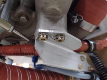
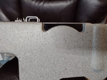
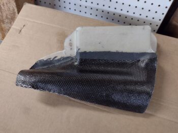
I started out this morning by creating flox edges and micro’ing up the foam surfaces before laying up a ply of BID inside the GIB throttle quadrant bolt head retainer pocket I made on the sidewall.  Again, this little pocket allows the GIB throttle quadrant to be mounted flush up against the sidewall and minimize its intrusion into the cockpit.

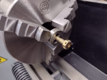
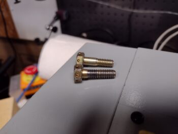
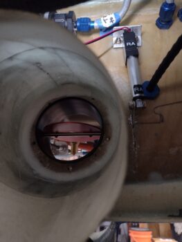
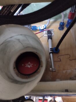
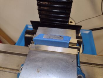
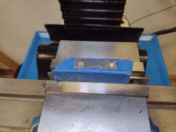
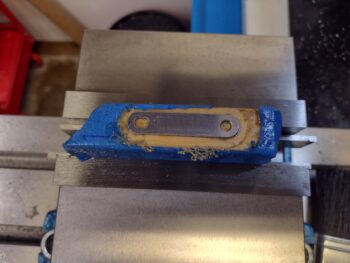
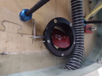
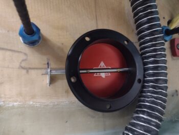
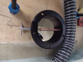
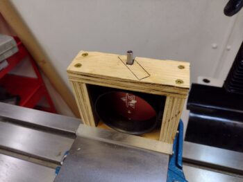
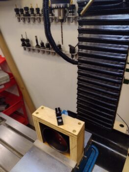
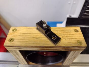
While the BID layup inside the bolt head retainer sidewall divot cured, I tweaked the inside measurements of the RAM air can butterfly valve lever attachment hole to tighten it up.  To check out my new dimensions I did a quick few 3D printed versions of the lever.

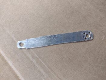
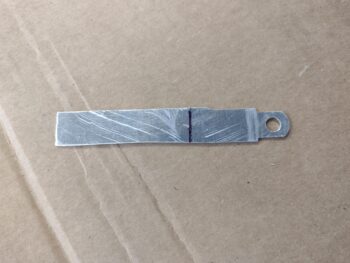
Here we have the initial machined aluminum RAM air can valve lever and a few versions later with a 3D printed mockup.

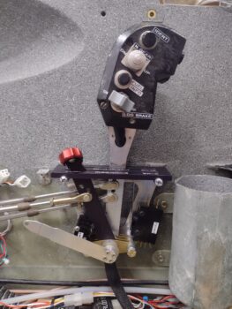
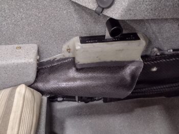
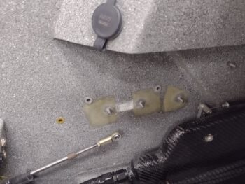
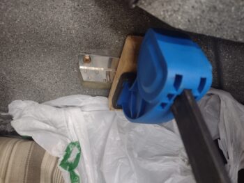
A few hours later, after I razor trimmed the glass layup on the quadrant bolt head retainer sidewall pocket, I then test-installed the GIB throttle quadrant.  I used the wide 970-3 washers on the Clickbond posts at this point since I’ll need to make an indentation or two on the regular smaller washers to fit in between the rivets poking through the lower quadrant bracket.

I’ll take an opportunity here to comment on the placement of this GIB throttle quadrant.  It is definitely mounted in a spot that is NOT optimized for normal throttle manipulation as you have in the front seat.  Specifically, this GIB throttle quadrant is for an emergency where the pilot (me) may be incapacitated for any given reason.  It provides the GIB the ability to control throttle inputs to the engine, but except for taller passengers, most likely it would entail the GIB having to loosen or remove their shoulder harness to reach forward to manipulate the GIB throttle handle.  With the cavernous canopy I have this presents no issue for any height passenger since there is plenty of clearance for one to lean forward in the back seat.

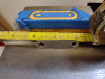
To secure the throttle cable to the sidewall I was going to use the first fuel injection servo throttle lever cable bracket tab that I machined, but had the bolt holes drilled at the wrong angle and thus couldn’t be used…. and was just an extra piece of metal at this point.  However, the cable transit & mounting hole was set too far out away from the other right-angle attachment side, which would have resulted in the cable simply being too far out from the sidewall.  I just don’t have the space down in the channel between the thigh support sump outboard wall and the inside of the sidewall to mount that “tall” spare aluminum bracket.

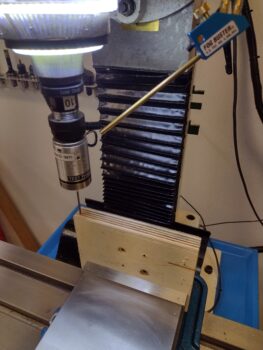
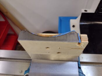
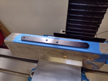
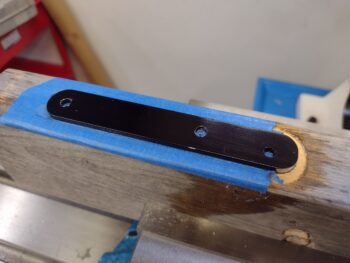
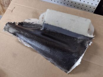
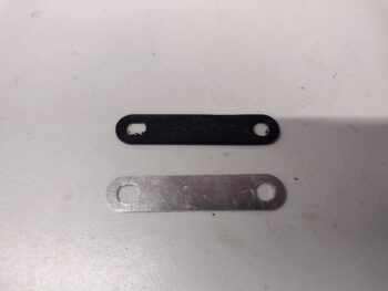
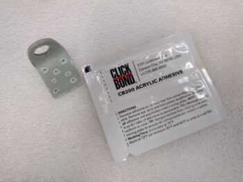
Years ago I made up a long “L” bracket by simply laying up 8-9 plies of BID on the corner of a 2×4.  I never ended up using it, but decided it would be perfect for this application so I cut a chunk off of it to use for this cable mounting tab.  I then drilled the 0.46″ hole and shaped the tab around the hole.  Finally, I drilled some smaller grip holes into the side that actually attaches to the sidewall.  Moreover, since I need to be able to place it in a very exact spot and have it stay there, I couldn’t mess around with flox and didn’t want to use 5-minute glue for attaching the entire thing.  For just a purpose as this I’ve been saving a packet of Clickbond CB200 acrylic adhesive in reserve, so I grabbed that to use here.

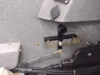
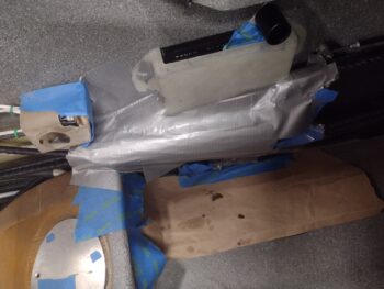
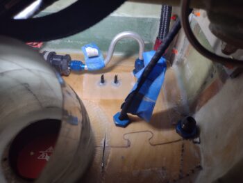
I then prepped the mounting tab and the mounting surface with some sanding and acetone cleaning in prep for the GIB throttle cable mounting tab attachment.  I then mounted the cable into the tab using blue Loctite before cinching up the retaining nuts.  Finally, since I wanted to ensure and verify my spacing is correct, I remounted the HEIM rod end to allow attaching the cable end to the throttle lever so the spacing would be maintained during cure.

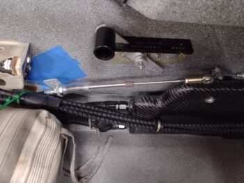
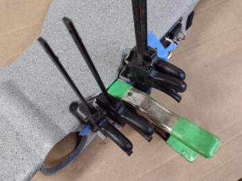
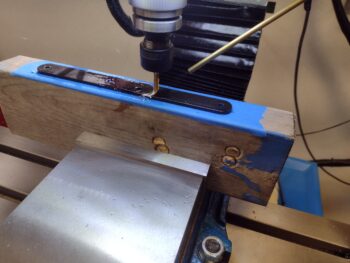
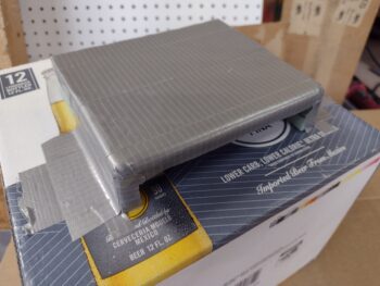
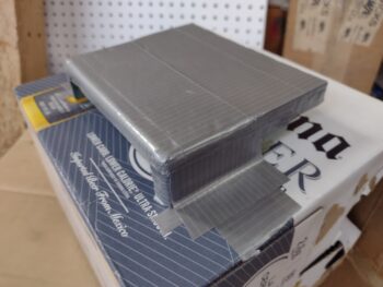
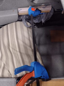
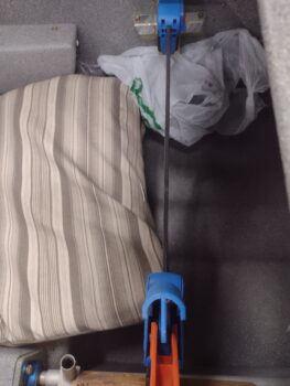
It took a bit of machinations to get the GIB throttle cable mounting tab situated in the right spot, and not surprisingly I made a decent bit of a mess with the acrylic adhesive.  Admittedly, this packet of CB200 is a bit past its shelf life date, so instead of the claimed 3-5 minute working time (which I still think is a bit optimistic) I ended up hanging upside down over the strake and into the back seat for about 15 minutes holding this mounting bracket with a large screwdriver to keep it pressed up tightly against the sidewall.  I had the cardboard and stir stick on the seat next to me so I could check the curing status while keeping the bracket held firmly in place.

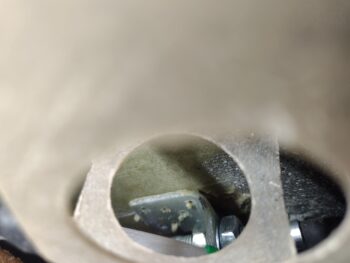
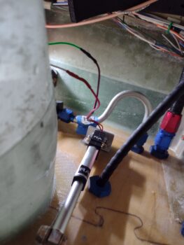
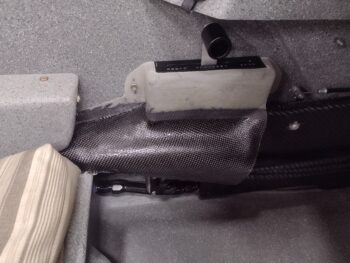
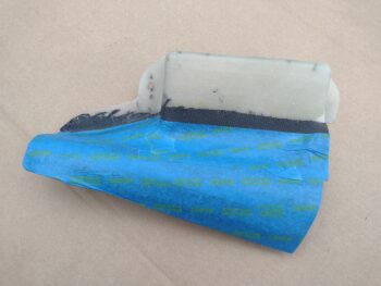
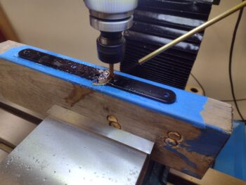
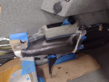
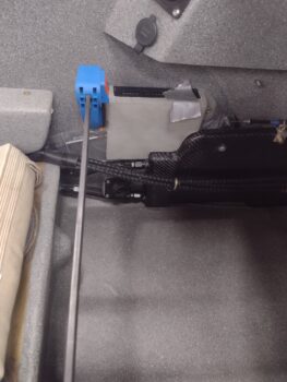
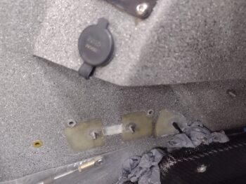
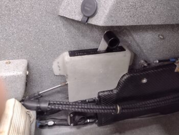
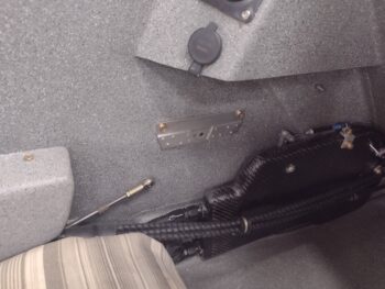
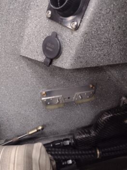
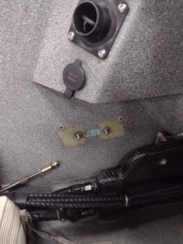
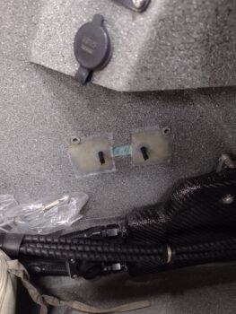
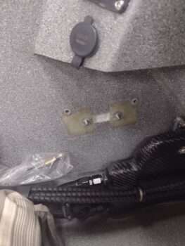
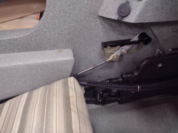
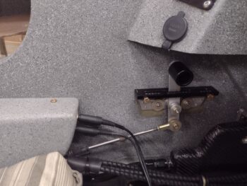
Here we have the GIB throttle cable mounted to its sidewall mounting tab, which is itself mounted via acrylic adhesive to the sidewall.  This was about 30 minutes into the cure time after I removed the blue tape that I placed to keep the adhesive from gumming up my nice paint on the sidewall just forward of the thigh support cross bulkhead (below the front edge of the left armrest bracket).

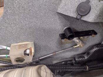
Due to a social event I had this was actually only about a half workday so about 6 hours later, late in the evening, I checked the cure status of the acrylic adhesive.  The literature on this CB200 says that at 2 hours in room temperature the bonding is at 90% strength, so I figured I was good to manipulate the throttle at nearly 7 hours later.

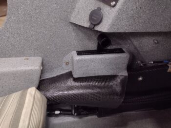
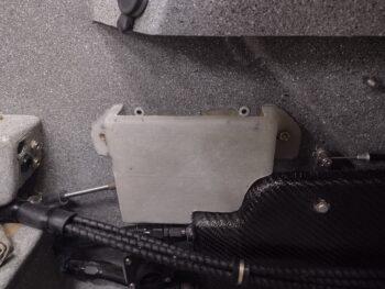
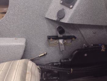
As you can see, I put the left GIB armrest in to get a visual on how the GIB throttle install looked.  Not bad IMO!

As I had done previously, I then double checked the clearance with the headset jacks to ensure I could get the cables in and out without too much hassle.  As par usual, the clearance is a bit tight, but definitely doable.

Tomorrow my focus will be in constructing and glassing a cover for the throttle quadrant and cable arm to ensure nothing obstructs their functioning during flight.  Also I’m going to extend the cover down to shield the throttle and mixture cables transiting over the face of the heat exchanger to ensure they don’t get torn up, damaged or chafed over the ensuing years of GIB passengers climbing in & out of the back seat.

Chapter 23 – GIB Throttle & RAM can

I actually started on the back seat throttle today by pulling the front left armrest off and doing the FINAL hookup of the throttle and mixture cables to the pilot throttle quadrant levers.  Normally I think of final and permanent installs as never really “final” or “permanent” since something always seems to crop up that requires uninstalling whatever it is that was installed for a “final” time.  I can tell you that it took me over 45 minutes to install just 2 cotter pins into the clevis pins that secure the throttle and cable rod-end forks to the levers… there is about zero clearance and very little capability to see up under there.

Moreover, I couldn’t reverse the clevis pins so that they stuck inboard since the frame of the quadrant was in the way, at least on the throttle lever.  So my intent after all this pain is to never have to reinstall those clevis or cotter pins again.  What a major, major PITA that was!

That being said, with the primary throttle cable installed, I then temp installed the cable that runs back to the GIB throttle.  I played around with the settings for another good 45 minutes, drilled a couple more holes in the GIB throttle quadrant lever to check the actuation and movement of the cable, lever and handle… but after a point my data collection was maxed out without the GIB throttle quadrant being actually mounted in place.

I did have enough data and info in hand to feel comfortable mounting the GIB throttle quadrant to the wall, so I pressed forward with that.  I’ll come back to the final rod end spacing and lever hole tweaking after the GIB quadrant is hard mounted to the sidewall.

First up, I disassembled the GIB throttle quadrant and used the back plate to mount 2 prepped RivNuts with AN3 bolts, after which I floxed the RivNuts into the 2 holes I had just drilled into the sidewall.  I then used a spreader clamp to keep the RivNuts securely pressed into place.

A few hours later I pulled the spreader clamp and cleaned up the flox around each RivNut… I then test fit the GIB throttle quadrant backplate back in place… it looked good so far.

I then drilled out two 3/16″ holes in the lower portion of the backplate, prepped and inserted 2 Clickbonds and floxed those to the sidewall as well… again using the spreader clamp to keep them firmly pressed into place.

Here we have the aft Clickbond showing as it’s floxed into place on the GIB left sidewall.

Again, a few hours later I pulled the spreader clamp to see how the Clickbond floxing turned out.

I then carefully removed the quadrant backplate, prepped and glassed the 2 Clickbonds to the sidewall using 2-ply BID layups.  I then of course peel plied the layups.

Note the small divot in between the Clickbonds: this is for the bolt head retainer on the outboard (back) side of the quadrant backplate.  I simply decided to mount the quadrant flush up to the wall and to do so I needed to provide space for this retainer… Later I’ll glass in this divot.

While the Clickbond layups were curing I then got busy machining the small 2″-long lever for the RAM air can butterfly valve.  This lever will poke forward from the RAM air can butterfly valve pivot rod into the Hell Hole through a small slot in the firewall and be manipulated by an electrical actuator.

I have some stainless steel on hand that will make up the final lever, but for purposes of fitting, testing, and getting the actuator installed, I’m using 0.04″ thick aluminum to dial it in. It just so happens that as I was poking around to find a good piece of scrap to use, I found the previous throttle friction lock lever to be the perfect candidate to convert for this test lever.

After trimming off each end, I then mounted the 0.04″ thick aluminum for machining.  Here it is after the holes were drilled on each end.

And after I finished machining it completely.

To give you an idea of the diminutive size of this thing I set a tape measure next to it.  As you can see it’s not even quite 2″ long.

It was getting pretty late, so with this last task complete I called it an evening and let the Clickbond glass cure overnight.