Chapter 11/13 – Fairing bottom glass

Today I started out by trimming and shaping the bottom foam surface of the elevator fairings.  I also aligned the elevation of both fairing bottom surfaces with their respective fuselage-side securing nubs.

I then trimmed and removed the foam from the aft approximate 0.4″ trailing edge of both fairings to allow for a glass-to-glass bond between the top and bottom fairing glass surfaces.

I also created a flox edge around the thread CAMLOC phenolic insert.  Here we have the left elevator fairing….

And the right side elevator fairing, prepped for glass.

The end result, as shown here on the left side fairing, was a glassed (with 2 plies of BID) and micro’d elevator fairing.  The right side of course looked pretty much the same.

Tomorrow I plan on working on glassing both the front fairing face, and the outboard side face as well. In addition, I plan on working on the instrument panel until I finally get that knocked out.

Chapter 11/13/21 – More fairing nubs

I started off first thing today by laying up glass on both the upper and lower sides of the elevator fairing securing nubs.  The tops got 2 plies of glass with a ply of BID atop a ply of UNI.  The bottom side got 3 plies of glass, with a ply of UNI sandwiched by a single ply of BID each side.  I then peel plied the layups.

I then got to work on a serendipitous discovery I had last night… and not potentially a good one . . .

Although I failed to get a shot of it as I was in somewhat of a hurry to get out the door last night, while recovering a Korey Light that had fallen down into the back seat area through one of the control tube pass-through holes in the front seat bulkhead, I happened to notice a small pond of the water in the GIB seat pan… just aft of the GIB thigh support sump tanks.

“Uh-oh!” I thought to myself, as I wondered if I had a leak in the right sump tank… as that is where I had let the water drain from the main tank to then exit out the hole on the bottom of the sump tank –where normally a drain valve would be mounted.  The only other area that could be leaking I hypothesized is the area around the 1/2″ aluminum tube between the main tank and the sump tank.  So I figured I would test both the right sump tank itself, and the fuel tube that transits the fuel from the main tank to the sump tank.

However, after cleaning out the water in my GIB seat pan, and climbing in to take a look, I realized that I had at some point —that I clearly didn’t remember— taped across the sump tank drain hole on the bottom floor of the sump tank to keep out dust, debris and critters until the drain valve was installed.

Moreover, when I had pulled the drain plug on the main tank the taped hole in the sump tank was letting just enough water through that I thought it was draining as it should… but clearly it was restricting the exit flow.

My initial test last night consisted of mimicking the previous process, so I filled the right sump tank via the main tank’s corner fuel exit drain.  The only difference was I had pulled the internal tape and installed the drain valve.  I also pulled the armrest off to check for any signs of leakage, and there were none.  Now, I should note that in prep for eventually configuring the sump tanks post-strakes, a while back I had taken all but 3 screws out of the top access plates.

Fast forward to this morning… after a whole night of holding water in the right sump tank with no leaks, my conclusion was that the exit flow from the sump tank, having been restricted by tape, caused the the water to overflow the top access port —which was secured only by 3 loosened screws— and simply flow down into the GIB seat pan.  There was zero signs of any leaks.

One thing this test also allowed me to do was drain all the water into a bucket and determine that the right sump tank holds 1.25 gal as collected, and by adding a minimal pint into the mix due to the unfilled area left forward of the access port (I expect it will hold closer to another quart) I’m calling the right sump tank fuel quantity at 1.35 gallons.

Moving on.

After checking my layups on the elevator fairing nubs to find that they still needed a bit more cure time, I decided to knock out the design and initial wood cutting for the fuselage dolly I’ll need to support the inverted fuselage after I flip it for shaping and skinning the bottom strakes.

I rounded up a bunch of scrap wood and cut it to length as I had annotated on my cut sheet.  Step 1 of the inverted fuselage dolly complete.

By this point the glass layups on the nubs had cured, and I proceeded to pull the peel ply, razor trim the excess, and redrill the CAMLOC stud holes.

I then remounted the aft nose/avionics cover to verify the fit between the glassed nubs and the elevator fairings.  I had to do a couple of iterative tweaks on the right side, but it seemed to finally settle in.

I then took all the water I had previously drained out of the right sump tank and repeated the entire test on the left sump tank.  I saw no leak issues from the main tank to sump tank fuel line, and although I only had the water in the left sump tank for about an hour before I left the shop, there were no evident leaks.

I left the water in the left sump tank to sit overnight and will check for any leaks tomorrow.  And as per my current usual, tomorrow I’ll continue work on both the aft nose/avionics cover elevator fairings and the instrument panel to get those knocked out pre-fuselage flip.

Chapter 11/13/22 – Elevator fairing nubs

I started off today taping up around the elevator fairing nubs to protect the area from any errant flox or epoxy during the attachment of the nubs to the fuselage.

I then prepped each slot with micro on the foam and then flox in the corners and edge of the slot.

Not visible in these shots of the elevator fairing attachment nubs are the ply of glass I wrapped around the inboard half of the nub that is internally secured in the sidewall.  This essentially creates a 1-ply glass bond between the top outboard edge of the slot to the inboard wall, then the same on the bottom.  I figured I would simply help add some glass back in the mix to bolster and reinforce this area as much as possible.

As you can see, I have thick black Gorilla duct tape on the top surface of the nubs to both help protect it during floxing and glassing ops, but also as a spacer to help mimic the 2-ply glass layup that the top surface will receive.

I then reinstalled the aft nose/avionics cover and buttoned it down with CAMLOCS in various spots.  There are actually CAMLOC studs securing the nubs to the bottom of the fairings, so to ensure that I had as snug of a fit against the sidewall as possible I taped the fairings to press them inwards.

As the nub-securing flox and glass cured, I got back to work on the instrument panel… specifically on widening out the mounting holes in the original composite panel to allow the installation of the Korey indicator lights in the row just over the HXr EFIS.

I started by applying duct tape (this time, I think it holds better than the blue painters tape in this application) over the row of lights and then reinstalling the panel over the tape.

I then used a razor knife to cut the outlines of the aluminum panel face Korey light holes into the tape and then removed the cut tape from the holes.

I then removed the panel again and proceeded to cut out each hole using the tape outline as a rough guide, and just kept at it for nearly an hour until I could insert a Korey light into each mounting hole.

I also grabbed a wider angle shot of the front cockpit and panel to show the 2 pilot air vents… one on each side.

Here we have a shot, many hours later, of the elevator fairing nubs secured to the sidewall with cured flox and glass.  I removed the tape and peel ply, and cleaned up the edges along the top and bottom edges where the nubs entered the sidewall.  I then reset the aft nose/avionics cover back in place —which of course now includes the elevator fairings— and re-secured the fairings to the nubs via CAMLOCs.

Note that since the smallest sized CAMLOC studs are -2s, I needed to use some washers to ensure a tight fit between the nub and fairing underside.  I will re-assess these -2s after I glass the tops and bottoms of the nubs to see how well they fit.

Here we have another shot with the CAMLOC studs removed.

And a final shot of the left and right side nubs floxed and glassed in place just by themselves.

As I was grabbing some shots of the nubs getting installed into the sidewall, I saw this shot of the underside of the forward aft nose cover… I thought it was pretty cool and showed a fair bit of the hardware for the aft nose cover, so I included it here just for fun.

Tomorrow I’ll continue on with my elevator fairings install and final tasks on the instrument panel… all again in prep to flip this bird over and glass the bottom strake skins.


Chapter 11/13/22 – Fairing mount nubs

I started out today with a quick 1-ply BID layup over top of all the Korey indicator light mounting holes for the row just above the HXr EFIS.  These holes got fairly mangled by the Fein saw so I’m trying to add a little meat back on the bones before I go after them again with the Dremel tool to ensure the Korey lights fit as designed.

Back to my panel-mounted air vent… so I bought what I thought was the same AveoAir ball air vent as the black one I stole to use on the right strake pilot vent.  I just figured it had increased in price. What I didn’t realize or notice is that ACS still sold the same model as the black one for over $20 less.

Here’s a shot of the new AveoAir Maxi air vent.  Again, I went with silver this time for more contrast with the panel.

Now, both air vent models are 1.5″ versions, but since the silver one is a higher airflow Maxi model not only does it cost more, but it also needs larger diameters for mounting… about 0.2″ both holes (since I’m embedding the vent backside part into the original composite panel, hole #1 AND the threaded interface of the front vent body through both the aluminum panel face and the glass edge on the original panel, hole #2).

My very first check was to fit the new air vent in the aluminum panel face overlay to see if it would fit.  Not only did it fit, but it looked MUCH nicer than my original black air vent, IMO.

I then needed to ascertain if I could make it so that this larger air vent could feasibly be installed in this panel configuration.  Below is my chicken-scratching drawing trying to define my mounting issues for this new AveoAir Maxi air vent to see if I could make it work.

I determined that I couldn’t increase the size of the backside panel hole since it was already infringing very closely into one of the mounted nutplate’s “personal” space, so I decided to decrease the diameter of back bracket by about 0.150″ (A/red). I then widened the narrower hole on the front panel face by around 0.2″ in diameter (B/blue).

I chose to do step B first, so I added and marked 0.1″ around the perimeter of the current vent hole.  I then used the sanding drum on the Dremel tool to make quick work of widening the diameter of this hole.

Step B:

Next up was Step A.  I chucked up the back piece of the AveoAir Maxi vent on the lathe and trimmed the diameter of the lip down by about 0.150″.


After my initial test fit into the back of the panel I had to go back for one more quick trim and pull a few thou off the diameter, but it went in nice and snug on attempt #2.

I then threaded on the front vent piece and Voila!  My panel’s new silver AveoAir Maxi high-flow air vent!

I then pulled the peel ply off the top elevator fairing layups and trimmed the edges of the glass. I have to say so far I’m really very happy with how these fairings are turning out.

I then marked up the locations on the fuselage –just aft of the elevator tube offset entry hole into the fuselage– for what will be 1/4″ thick G10 phenolic securing brackets, AKA “nubs,” for securing the aft nose/avionics cover-mounted elevator fairings to the fuselage… just one of the many securing points to keep the rather large yet lightweight aft nose cover attached to the aircraft.

After marking the fairing-securing nub locations, and a double check of thickness and width, I then cut a slot on each side of fuselage for these respective nubs to get floxed into.

At this point it was time to actually create the phenolic nubs.  I took my 1/4″ thick G10 phenolic bar out to the table saw and ripped it to 1.05″ wide.

Then on my chop saw I cut 2 pieces from the ripped portion at 1.95″ long to create the 2 elevator fairing mounting nubs.

I then test fitted the nubs into my previously cut slots… here’s the left side looking forward.

And a shot of both test-fitted elevator fairing mounting nubs looking aft.

I then mounted the aft nose/avionics cover –which at this point includes the attached elevator fairings– to test the fairing-to-nub interface.  I did a bit of minor dialing-in to these interfaces for a good half hour until I was satisfied that all was good.

Here’s one last shot of the elevator fairing-to-fuselage mounting nub interfaces.

It was quite late at this point so I called it a night.  Tomorrow I’ll flox/glass these nubs into the fuselage as they are held in the correct position via installed CAMLOC studs to the actual elevator fairings.


Chapter 11/13/22 – Elevator fairing glass

As a reminder, as of last night this is what the threaded CAMLOC receptacle blocks looked like glassed into the bottom-side notches on the elevator fairings.

Clearly the left side layup is having some issues.

I cleaned up the right fairing layup and it looked great… then I cleaned the plastic out of the threaded CAMLOC receptacle.

And ops checked a CAMLOC stud fastening into the embedded receptacle.  All good.

I then focused on the left fairing’s embedded CAMLOC receptacle block. I stripped the majority of glass off and sanded it in prep for new glass.

I then laid up 2 new plies of BID over and around the embedded CAMLOC receptacle block.  I then peel plied just the face of the phenolic block.

A few hours later I pulled the peel ply, razor trimmed and cleaned up the layup.  A huge improvement over the previous nasty layup.

Again, I dug out the plastic from the threaded CAMLOC receptacle and then ops checked a CAMLOC stud.  Again, all good.

I actually attached the right elevator fairing to the aft nose/avionics cover with micro while the left aileron fairing’s embedded CAMLOC receptacle block reglassing cured.

After I gave the left elevator fairing’s embedded CAMLOC receptacle block glass a GO, I then micro’d it in place as well.

While the attached elevator fairings’ micro cured, I then got to work on the panel.  This is actually the first time (IIRC) that I’ve had the black panel inside the plane.  I really like how it looks.

I then spent about 2 hours trimming the glass and foam away on the composite panel structure to all me to install the Garmin GNS-480 Korey indicator lights (look mid-left). I also trimmed the hole for the N-# Korey light at top left so that it would fit as well.

Here’s a closer up look at what I was working on.

BTW, what DID NOT fit was the new silver Aveo air vent.  I must have ordered the wrong one or they sent me the wrong one because it is not a direct replacement for the black vent that I stole to use for the strake leading edge vent.  I’ll have to do some research and make some decisions on this vent.

I then took the shims off the right elevator and could tell it was secured onto the aft nose/avionics cover very well.

After the left side cured, I then opened up the aft nose/avionics cover… here’s a shot of the elevator fairings with the cover open.

And a side view of the left elevator fairing when the cover is opened.

I then sanded, shaped, and prepped both elevator fairings for glass.

And then laid up 2 plies of BID on each elevator fairing, overlapping onto the aft nose/avionics cover.  I then peel plied the layups.

Tomorrow I’ll continue to work on both the elevator fairings and the instrument panel.

Chapter 11/13 – Elevator root fairings

I got back from my weekend trip a bit earlier than expected, so I was able to get out into the shop in the very late afternoon.

I started by spending a good 45 minutes emptying the water out of the right fuel tank. When it got low enough I just pulled the plug and let the water drain from the main tank exit drain down into the right sump and then out the sump drain hole, which doesn’t have the drain plug installed currently.

I then got busy designing the elevator root fairings.

After assessing the inboard elevator area and interface with the aft nose/avionics cover I put my design down on paper.

After a few iterations I narrowed down my fairing profile on paper and cut it out.  I then test fit it on the aft nose/avionics cover.  So far so good at this point.

I then rounded up my piece of PVC foam and taped my fairing profile to it.

I then traced out the template to create 2 fairings.

I marked the excess foam to be removed . . .

And cut it off with my mini-hack saw.

Because the block of foam was so thick, I used my small band saw to cut out the fairing blocks.

Voila!  Initial foam fairing blocks shaped.

Another shot of the foam fairing pieces.

Clearly a bit of trimming still required at this point.

I marked up the left foam fairing block for trimming and shaping.

And worked both sides to get the foam fairing blocks to fit.

I then made the radius cut on the aft side of each foam fairing block.

With the initial fit of the foam fairing blocks good, I then got busy on working stuff for the #2 purpose of these fairings: to help secure the aft nose/avionics cover to the fuselage via CAMLOC hard points.

To do this I’m going to embed a threaded CAMLOC (SkyBolt) receptacle phenolic block into a bottom-side notch on each fairing.  That will lock to a floxed and glassed G10 phenolic nub protruding out of the fuselage sidewall approximately 1″.

I first cut a couple squares out of my 1/4″ phenolic stock.

I then drilled and tapped the phenolic blocks . . .

to mount the threaded CAMLOC receptacles into.

After stuffing the threaded CAMLOC receptacles with plastic saran to protect the insides, I the micro’d the blocks into place into their respective fairing notches.

A bit later I laid up 3 plies of BID over each phenolic CAMLOC receptacle block to secure it to the foam fairing block.  As you can see, the right fairing block layup turned out fine, whereas I’m definitely going to have to clean up and redo the left one tomorrow.

It was quite late so I called it a night and will hit it hard tomorrow!


Chapter 13/21 – Nose cover CAMLOCs

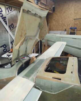
I continued on today with my work on the aft nose/avionics cover.  To reiterate, I want the aft nose/avionics cover install complete before I flip the bird over to shape and glass the bottom strake skins.

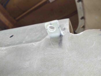
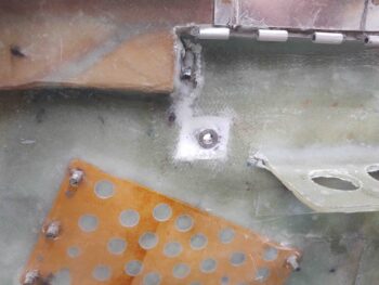
I started off by drilling the hole in the front right flange that will allow the nose side CAMLOC stud to engage the lightweight stainless steel CAMLOC/SkyBolt receptacle I riveted in place on the flange.

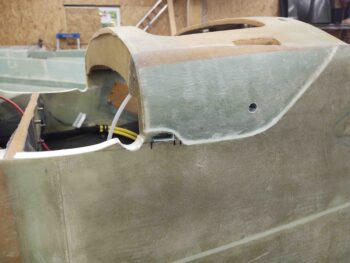
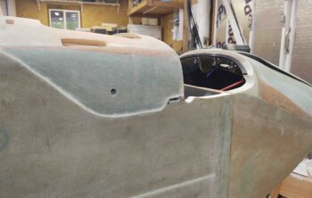
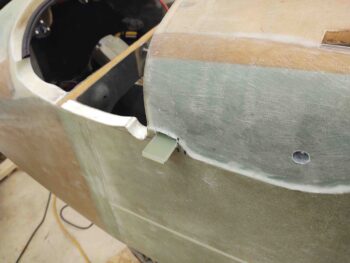
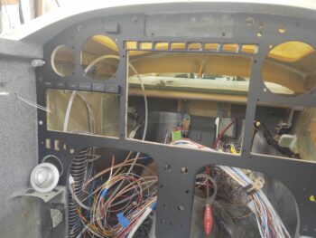
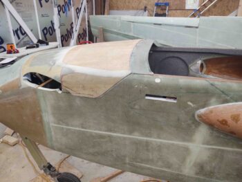
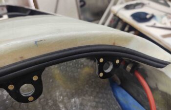
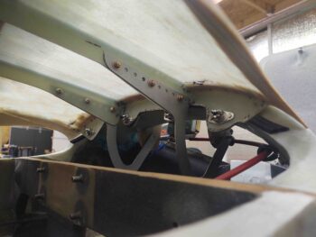
I then tested out the fit of both the aft nose cover and specifically all the 4 mounted CAMLOCs located on the front flange.  So far so good!

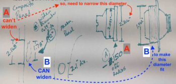
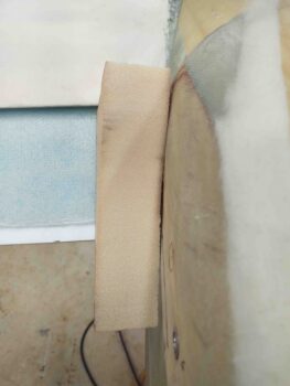
Note that I will be extending the outer flanges further outboard with glass to conform and compress the “B” seal as far outboard as possible.  This part of the nose curves to intersect the mating curve with the canard leading edge, so clearly I could not use straight G10 phenolic stock to create this section of the flange.  Moreover, I don’t consider this super critical and will do this task after I flip the bird back upright.

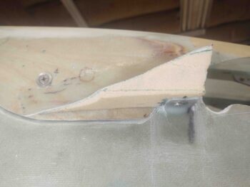
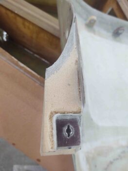
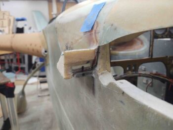
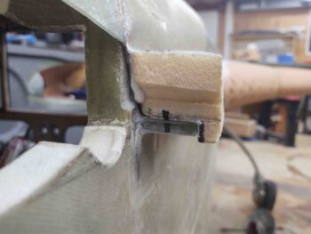
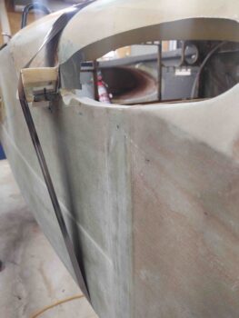
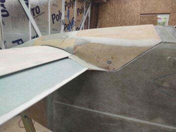
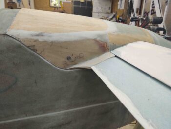
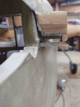
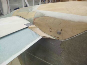
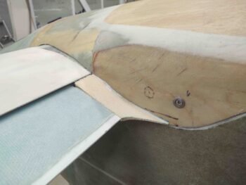
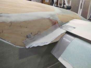
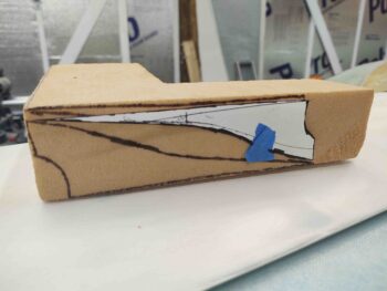
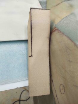
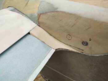
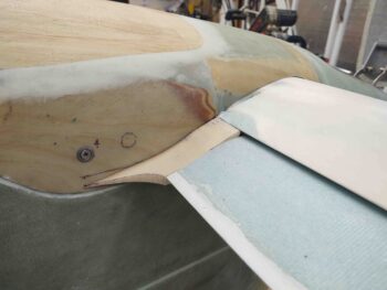
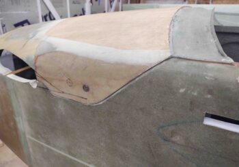
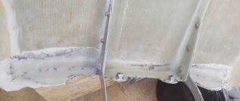
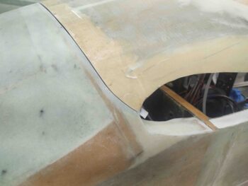
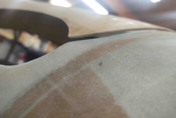
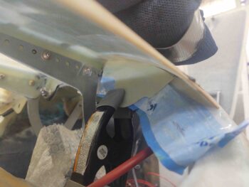
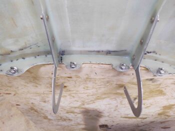
To ensure clearance with both the forward-situated nose bridge corner edge and with the canard as the cover swings either up to open or down to close, I trimmed the outboard flanges as close to each CAMLOC receptacle as possible.

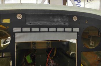
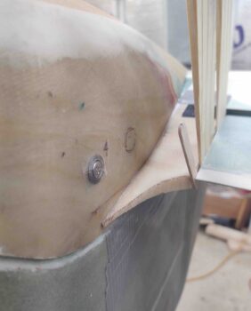
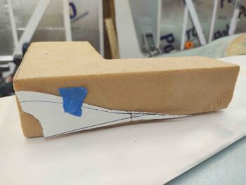
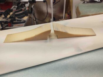
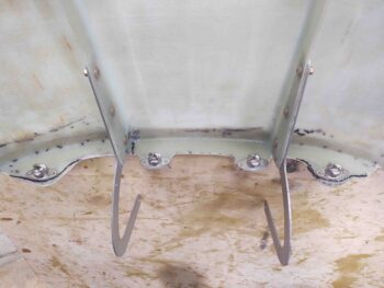
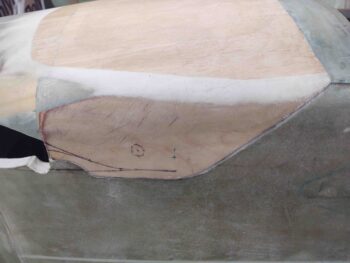
Here’s a before shot:
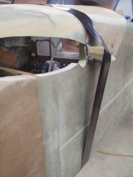
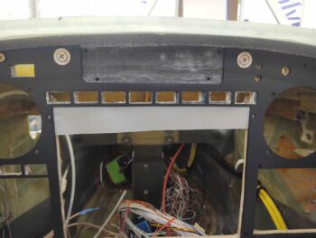
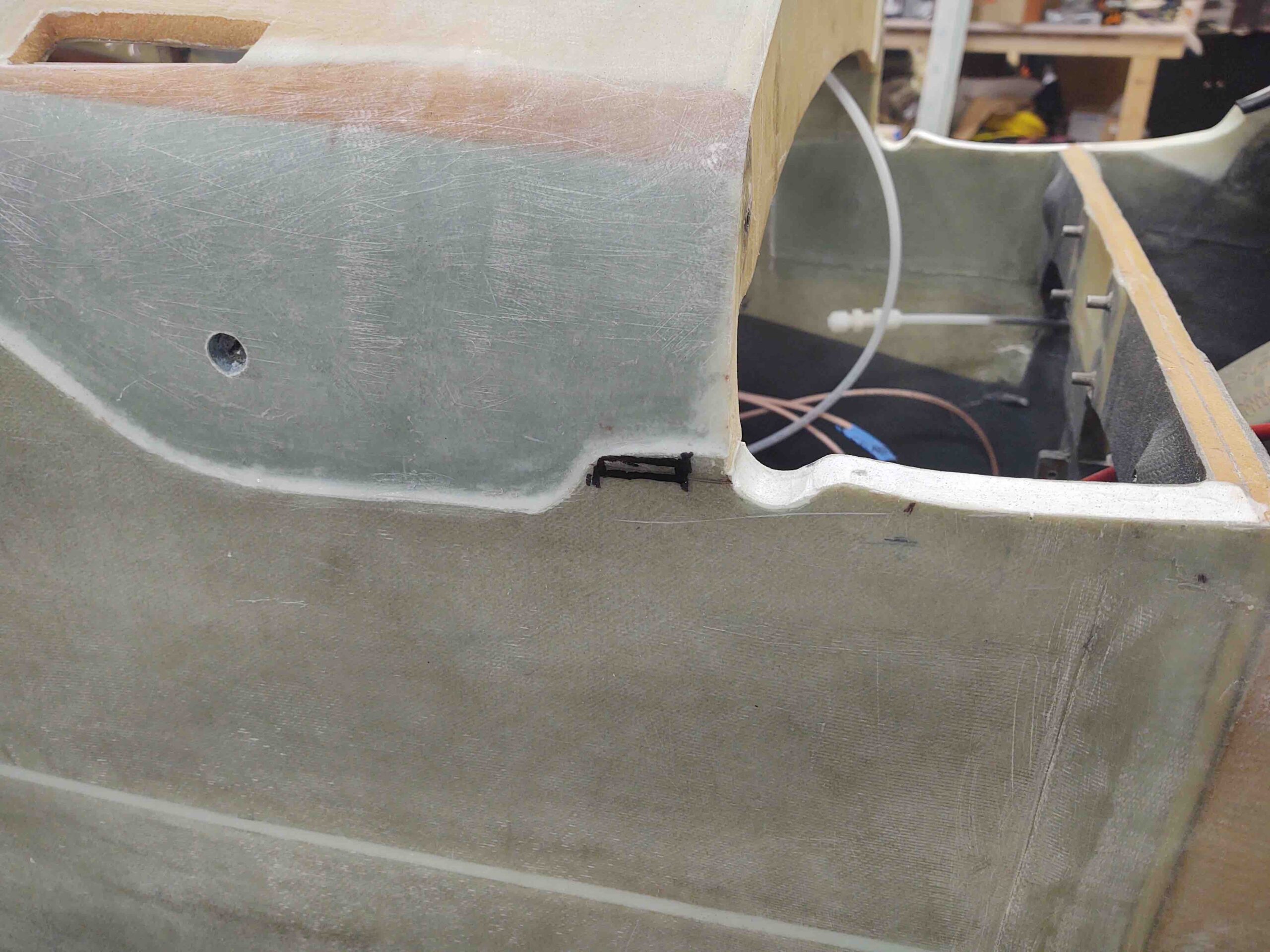
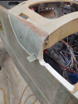
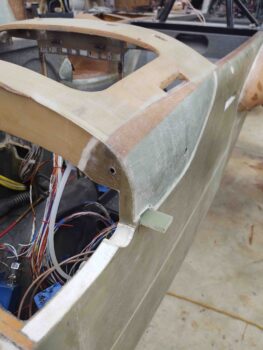
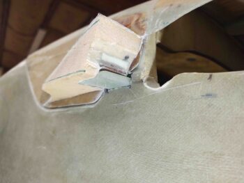
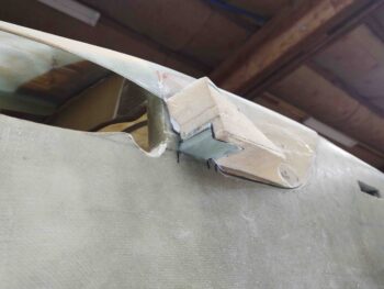
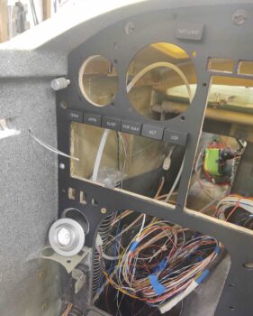
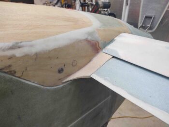
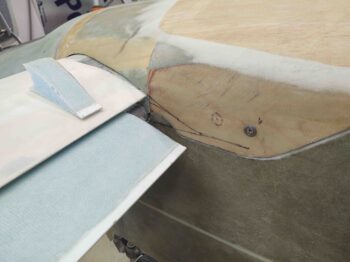
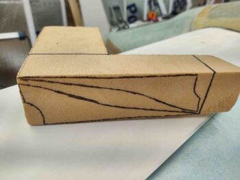
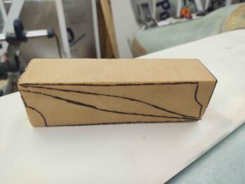
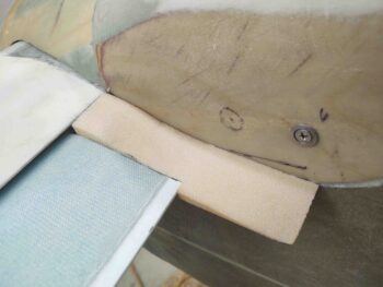
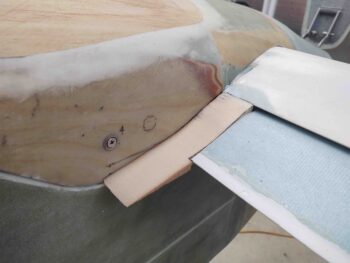
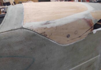
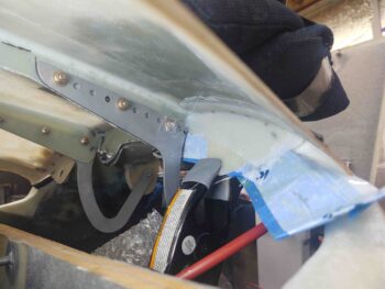
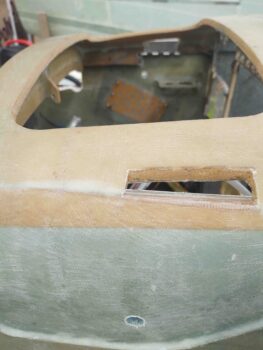
And post trim.

As I alluded to above, my priority is the securing of the aft nose/avionics cover to the airplane.  Secondary is sealing the gaps to keep moisture out as best possible.  So besides the very outboard flange extensions that will need to be glassed, the front flange with its 4 CAMLOC receptacles that secure it to the forward nose section is complete.

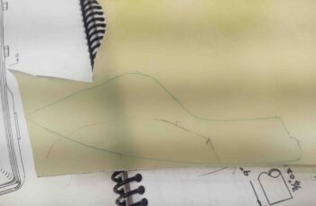
So just how is the aft nose/avionics cover secured to the airplane?  Well, there are 16 points that secure it (green denotes completion):
– 2 hinges that allow opening and closing of cover without removing from plane.
– 4 forward CAMLOCs (above)
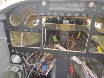
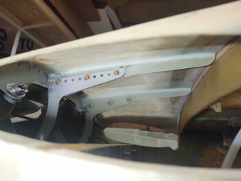
– 4 aft CAMLOCs (across top of instrument panel)
– 2 interlocking hinge segments with hinge pin (upper corner each side of panel)
– 2 CAMLOCs on each “flap” to pin them to the aircraft (discussed below)
– 2 inboard elevator fairing CAMLOCs that secures fairing to sidewall tab

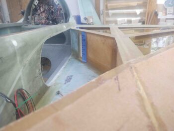
To have better access into the avionics bay to mount these next pair of CAMLOCs I chose to install them with the canard off.  Plus these are much less complex and a quicker kill than tackling the inboard elevator fairings.

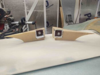
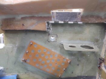
I started by doing an assessment on the final position for the CAMLOC on each side. Again, these pin down the flaps, which are fairly thin, to ensure they are literally not flapping in the breeze.

The factors as to where to locate these side CAMLOCs is a combination of optimum placement for securing the flap, relationship and clearance with the future elevator fairing, and also —and one of the most important— avoidance and clearance internal to the avionics bay side wall.

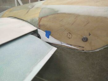
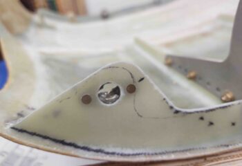
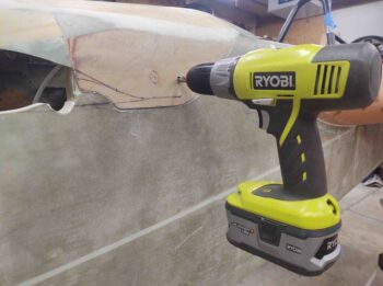
Once I cleared myself hot… and after confirming the position with a small pilot hole, I drilled the left side flap CAMLOC hole.

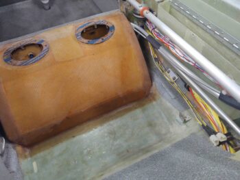
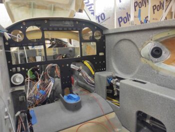
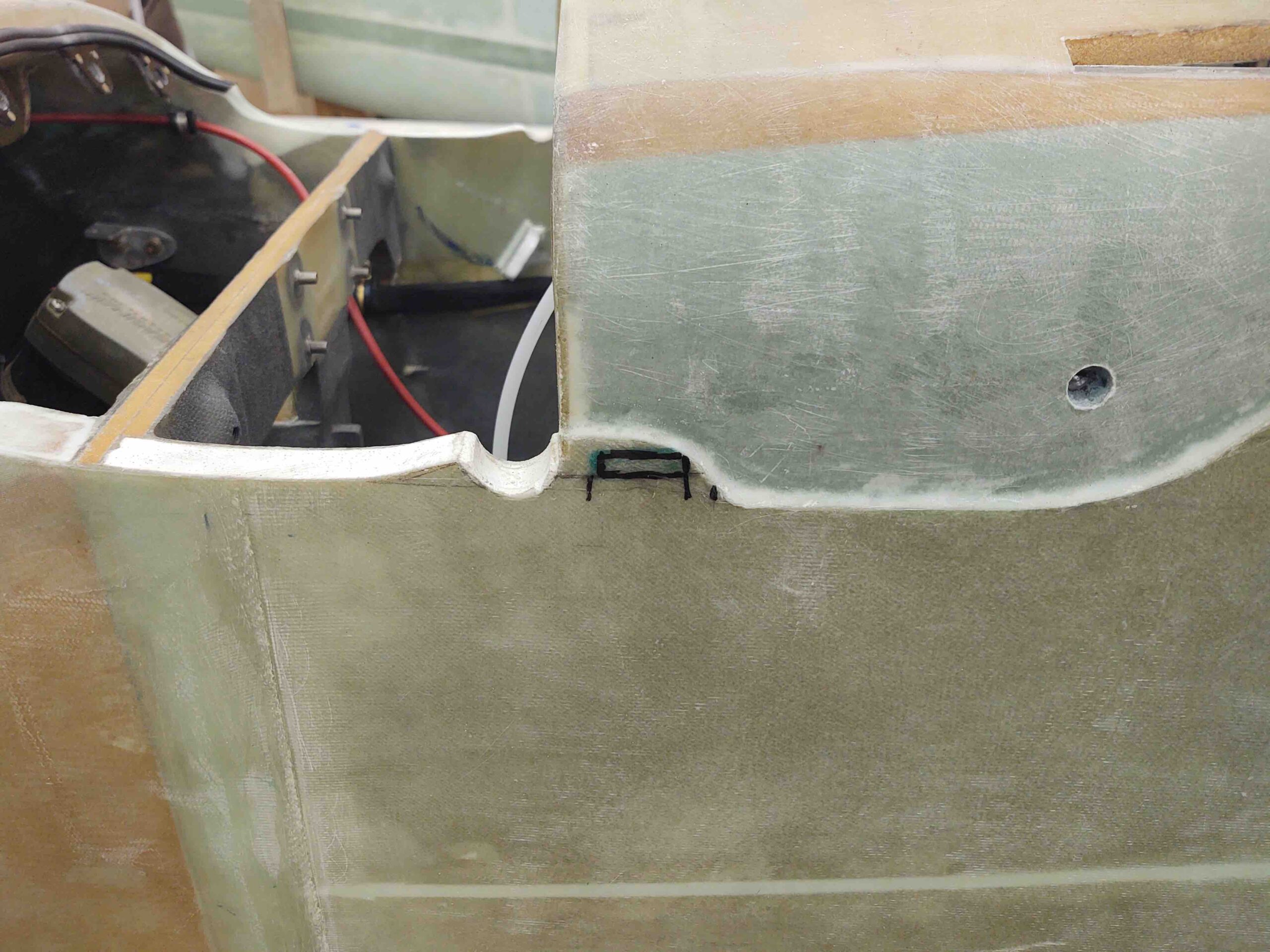
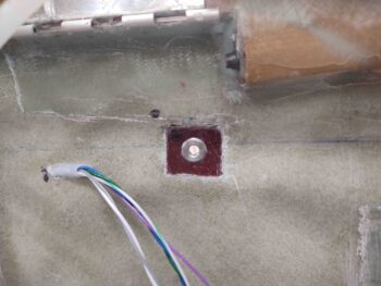
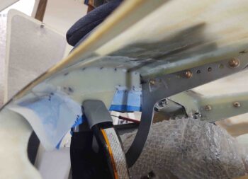
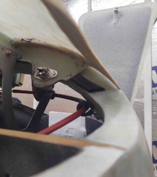
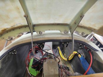
I then drilled the right.  As you can see, the right side (far side below) has both a cable connector bracket and the autopilot pitch servo to avoid.  Admittedly, and to be clear, these side flap CAMLOCs are in the same general location, but are not exactly symmetrical.

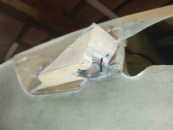
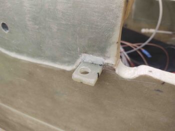
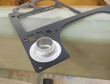
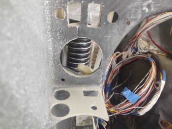
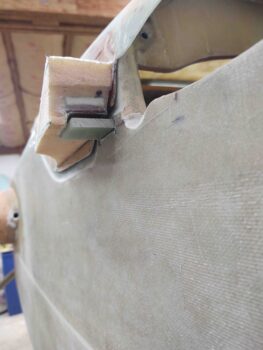
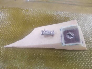
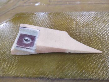
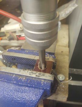
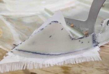
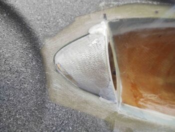
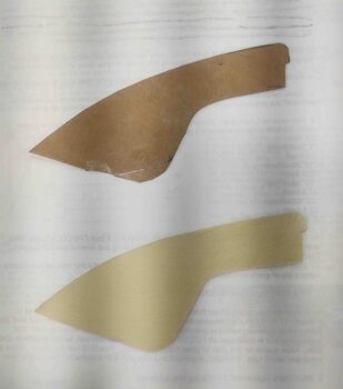
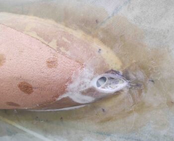
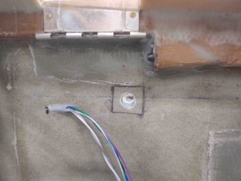
I then temporarily mounted the 1/4″ thick phenolic threaded CAMLOC receptacle block onto the surface of the right sidewall.  I then traced out the edge to mark the sidewall for cutting.

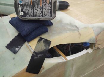
Then cut the sidewall and dug out some foam.  Although not really visible here, I dug out foam at the edges to create a flox corner.

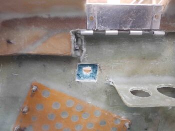
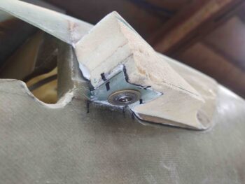
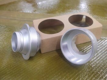
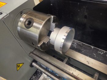
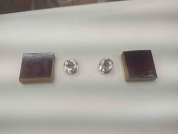
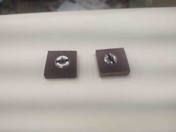
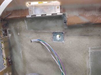
I then test fitted the 1/4″ thick phenolic threaded CAMLOC receptacle block. I made up these phenolic receptacle blocks quite a few months ago (November maybe?) and am just now installing them.

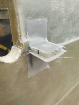
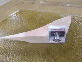
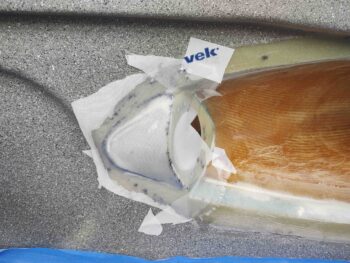
I then floxed the inside of the foam to create the flox corner around the perimeter of the hole, and then to also even up the foam surface a bit.  I then placed a small patch of BID into the hole, wet it out a bit and pressed the phenolic receptacle block –also slathered with wet flox– into the hole.

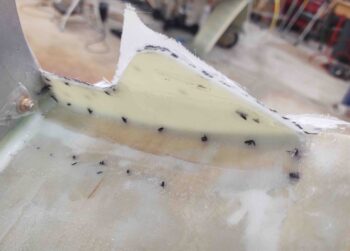
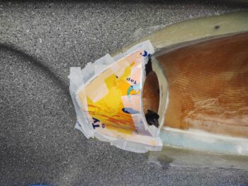
I then repeated the same thing on the left side . . . I temp mounted and marked the phenolic receptacle block perimeter edge.

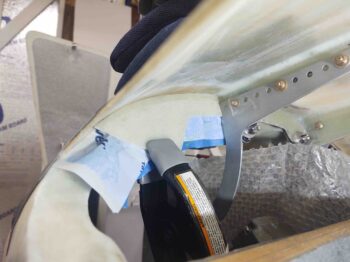
And cut the side wall glass with the Fein saw.

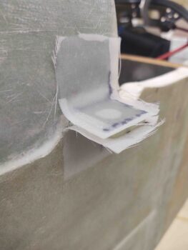
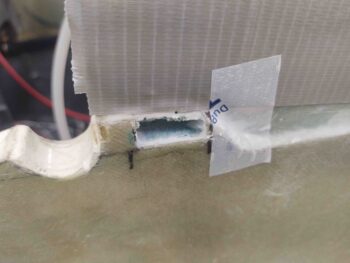
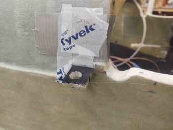
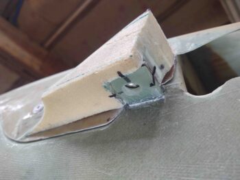
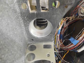
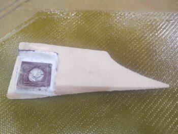
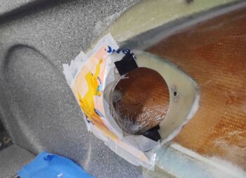
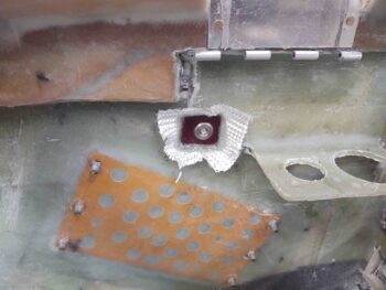
Same flox corners around the edge of the hole, with a ply of BID before I pressed the phenolic receptacle block into place.  Here you can see that I did prep the threaded CAMLOC receptacle by stuffing it with plastic (saran) wrap and then covering the front face with a patch of tape.  I did this previously on the right side as well.

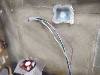
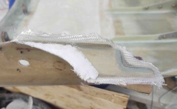
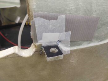
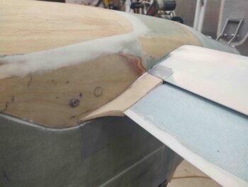
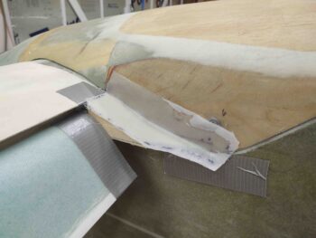
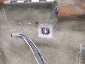
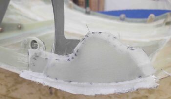
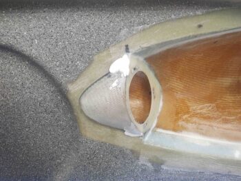
And here we have the left side phenolic receptacle block floxed and glassed in place. These steps for both sides were the initial, round 1 of glassing.

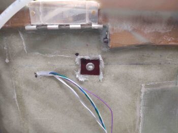
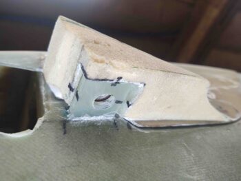
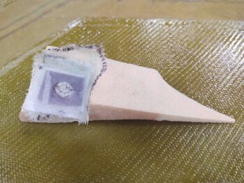
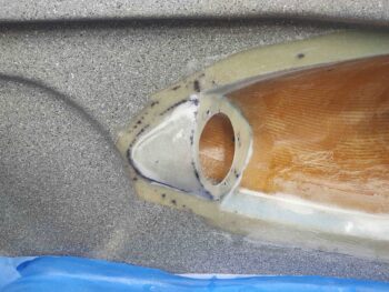
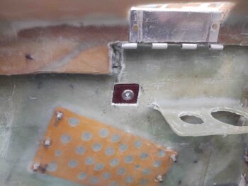
A few hours later I cut the cured glass around the phenolic receptacle block on the interior side.  The real fun was removing the glass, flox and plastic from the front face of the threaded CAMLOC receptacle.  It wasn’t overly difficult, but it did take a good 20 minutes per side.

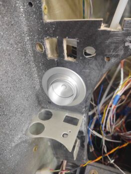
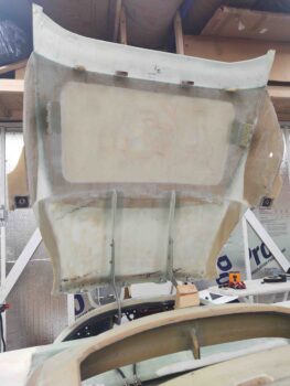
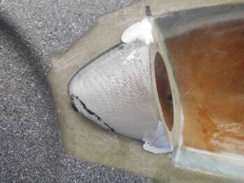
To ensure that the phenolic receptacle blocks are secure from the pushing of the CAMLOC stud from the outside in, I added a ply of BID on the inside that overlapped from each phenolic receptacle block onto the surrounding sidewall glass around it.  Since there was slight difference in elevation between sidewall and phenolic receptacle block on each side, I used micro to smooth out the transition.

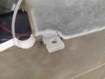
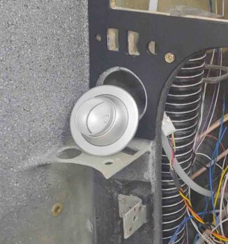
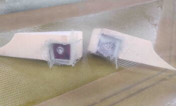
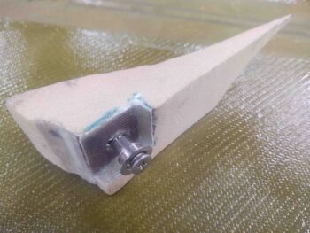
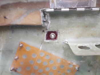
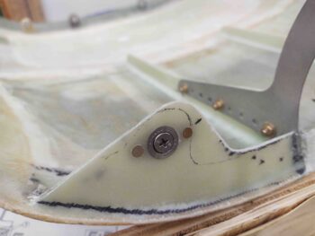
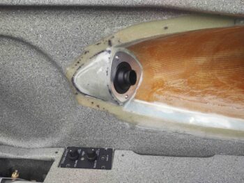
And Voila!  These layups complete the aft nose/avionics cover side flaps’ CAMLOC installation.

Since the interior ply of BID didn’t cover the center of the threaded CAMLOC (again, these are actually from SkyBolt) receptacle, I went ahead and placed the aft nose/avionics cover in place and locked it down at all the other CAMLOC stations as well.  Then I installed CAMLOCs at these freshly installed side flap CAMLOC points to have them cure completely in as correct position as possible.

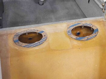
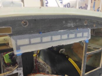
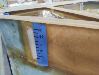
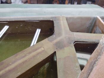
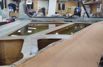
Although it was late, I wanted to get the test “fuel” (AKA water) transferred from the left tank to the right tank.  It took nearly 2 hours as I had to first prep the right tank (rubber stopper, drain valve install, remove tape, etc.) to be ready for the test fill.  As I did on the left tank I applied a strip of blue painters tape along the front edge of the fuel sight gage to annotate fuel levels in 2.5 gal. increments.

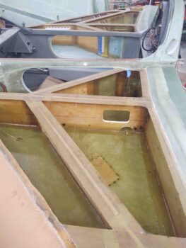
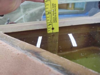
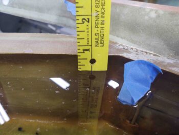
I then proceeded to transfer the water over from the left tank to the right tank (2x 1 gal, 1x 0.5 gal) and annotate the fuel site gage every 2.5 gallons.

I’ve been curious for quite a while just how much fuel my tanks will hold, and with this exercise I now know:
Left tank max capacity: 26.7 gal
Right tank max capacity: 26.3 gal

That’s obviously 53 gallons max capacity if I need it.  Not bad considering the elbow room mod takes such a big chunk of fuel out of the mix.  I’ve very pleased with the fuel capacity . . .

And even more pleased that again, just like the left side: NO LEAKS!!

I’ll be out of town for a quick trip this weekend (Sat & Sun) so no building on those days. I will of course be mentally contemplating my inboard elevator fairings and any ways to optimize or simplify those.

Chapter 13/21 – Left tank test fill

I didn’t get much done yesterday.  I ended up helping out a sick friend by watching her daughter for a while.  I did get started on positioning of the aft nose/avionics cover left flange CAMLOC placement though.

I was also able to lay up a ply of BID on the front side of the RIGHT flange on the aft nose/avionics cover…. which I peel plied.

I then laid up a ply of BID each on the aft side of both the right and left side flanges.  I then peel plied those as well.

Today I started out by pulling the peel ply and cleaning up the layups on each side flange.  I then finished drilling and installing the left flange CAMLOC receptacle… again, a lightweight stainless steel SkyBolt receptacle to be more precise.

I then did a final test fit of the CAMLOC stud… all good!

Yesterday I added about 10 gal. of water, with a bit of soap in it to reduce surface tension, to the left fuel tank.  Mainly to test for leaks of course, but I was also very curious about the capacity of the fuel tanks given that I had the inboard GIB elbow room mod and the subsequent added outboard fuel pocket.

I added the water 2.5 gallons at a time (technically 1 gal + 1 gal + 0.5 gal) in order to make my hash marks on the blue tape next to the fuel site gage.  Interestingly enough my fuel sight gage’s max topline indication is at 24 gallons . . .

while I was able to fill up the tank to 26.5 gallons.  My only limiting factor to adding –in my guesstimate– another 1/2 gallon was that the outboard of the tank was filled literally to the brim… or T-hat in this instance.

However, at the BL23/R23 rib I had a good half inch between water top and bottom edge of T-Hat.

At at the far back corner I had about 3/4″ more space to cram in some fuel.

Clearly the minimum max capacity of these tanks –IF the right fills to the same level (which I’ll test next)– is 53 gallons.  Possibly over 54 gallons.  Given the space lost to the GIB elbow room mod, I’m more than happy with that fuel capacity!

Moreover, I’m very pleased that without having even glassed the external bottom strake skin I have ZERO visible leaks!

I threw this video together to provide an overview of the strake and fuel tank build.

And with that, I called it a night!

Chapter 13/21 – Strake pilot vent done

I started today back on the aft nose/avionics cover.  With the 1-ply BID layup cured on the left front flange, I took the weights and tape off the top to check out the intersection between the cover and the nose…. not bad at all.  Clearly the ply of BID was securing the cover to the profile of the flange, something I was concerned was outside of the job description of 5-minute glue on its own.

In contrast, the right front corner of the aft nose/avionics cover still needs to have a flange segment created and thus the corner is still raised a bit.

I took this shot showing the 2 of the 3 tasks on the list to complete before the fuselage gets flipped inverted: the aft nose/avionics cover install, the right strake pilot air vent (finished, see below) and the final instrument panel install.

I removed the aft nose/avionics cover and laid up a ply of BID on the front side of the flange, after laying in a flox fillet.  I then peel plied the layup.

I had previously removed the peel ply from the aft side of the left flange and cleaned up the edges of that layup.  The aft side will get one more ply of BID for strength and rigidity.

I then got to work on the right strake pilot air vent structure.  After knife trimming the glass around the inside edge of the vent hole, I pulled the internal wall cardboard form off the internal 2-ply layup.

Overall it looked pretty good but I did have some sagging of the glass on the front lower edge.  It’s hard to tell in the pic, but the laid up glass was even with or even over-hanging the fuselage sidewall just a hair.  I could have slathered in some dry micro for the transition, but I wanted the convergence of the glass at this perimeter edge to flow more smoothly and evenly than adding more to the mix to cover it up.

Thus, like a plastic surgeon, I decided to do some judicious surgery here and remove the offending sagging area…. so I marked it first.

And then cut it out with my Fein saw.  I know when I’m creating one-off parts like this that sometimes it’s a very iterative process.  With such a small sliver missing, I started by glassing in a patch on the inside of the vent wall.  I also added micro and flox to the seams and this patched area about an hour before I laid up the actual glass… again, just to let it get fairly firm.

I then laid up 2 plies of BID as an external layup over the existing 2 plies for the internal layup.  While both plies overlap onto the fuselage sidewall, only the top ply overlapped onto the aft face of the vent structure (around the opening).  I then peel plied the layup.

About 5 hours later I removed the peel ply.  Due to all the black lines and white micro it’s a bit hard to tell that the flow is very smooth.  Once painted I think it will look really good and have very nice transitions.

I then installed the actual vent in its mounting plate to check out how it will look and function . . . Voila!  I’m very pleased with the outcome of this right side strake pilot air vent.

One reason I want to get these tasks out of the way before I flip the fuselage over is that they tend to be fiddly, in that it takes a lot of trial and error, fits, sanding, filing and refits to get these parts dialed in closely.

The same holds true on the aft nose/avionics cover.  I tell people that stop by to check out the plane build that I honestly think the aft nose cover will be one very cool and extremely functional part of the plane when its finished.  But man, oh, man is it a time suck to get this thing done.  I enjoy the creative process and try to enjoy the construction of it, but the time required to get this thing together is a bit much. Regardless, with the air vent now complete, I only have the aft nose/avionics cover and some remaining instrument panel install stuff left before I flip the bird.

With that said, I spent a good little bit of time creating a cardboard template, then dialing that in to transfer onto my 1/16″ thick stock of G10 phenolic to cut out.  I then did some final tweaking on the G10 flange before 5-min. gluing it up under the right side of the aft nose/avionics cover.  I clamped it in place while it cured.  Note that you can see some weighted shot bags above the flange on the top of the nose cover to wrangle the edge down into a more aligned position with the nose top.

After the 5-min. glue cured I laid up a ply of BID –again, to keep the front right corner of the aft nose/avionics cover aligned with the nose– on the aft side of the right flange and then peel plied it.

(Note the drilled 1/2″ diameter CAMLOC receptacle hole drilled in the left flange)

I then left this layup to cure overnight.


Chapter 13/21 – Nose cover stuff

Part of my initial tasks today was to peel ‘n stick the “B” seal on the aft edge of the nose bridge which will get compressed by the front flange of the aft nose/avionics cover.

Here’s a closer shot of the “B” seal on the right side of the aft nose bridge surface.

I then created a cardboard template of the left side forward flange for the aft nose/avionics cover and then traced out the cardboard onto my sheet of 1/16″ G10 phenolic.

Here we have the original cardboard template and the cutout G10 phenolic flange piece.

I taped up the aft nose bridge, the “B” seal and the hinge to protect them from the decent amount of 5-min. glue I slathered onto the edges of the left flange piece before clamping it into place firmly against the left CAMLOC tab.

I should note that this step came after spending well over an hour carefully sanding both the front edge of the aft nose/avionics cover and the aft edge of the aft nose bridge to get a fairly uniform gap and to be able to get the outer front edges of the aft nose cover to align elevation-wise with the forward nose surface.

Not surprisingly, both front outboard corners of the aft nose/avionics cover flare out just a bit higher than the surface of the forward intersecting nose.  So I weighed and taped this outboard front corner down to keep the intersection as even as possible between the two surfaces.

To really make sure the front outboard corner of the aft nose/avionics cover kept its shape and nice intersection with the forward nose edge, after the 5 min. glue cured I added a flox fillet on the aft side of the left flange and laid up a ply of BID to secure the aft side of the flange to the underside of the aft nose/avionics cover. I then peel plied the layup.

I then got to work on the right strake pilot vent inlet hole.  I sanded the interior of the hole and then sanded and shaped the outer edge of the hole.  It may not look the cleanest, but after a bit of cleanup micro and perhaps some inlaid glass during the strake skin layup it should be a nice rounded, smooth inlet.

With the major shaping of the external vent inlet hole complete, I then turned my sights to creating the inboard vent structure wall.  I used some thin cardboard to make up a template for the inboard wall . . .

And then laid up 2 plies of BID on the inside of the cardboard template, with the glass overlapping onto the interior edges of the strake vent structure, including the inboard edge of the aft face.

Again I should note that not only did I tape up the inboard surface of the template with smooth packing tape, but I then added peel ply so that the outer surface of this layup would be as ready as possible for an added external layup.

With that, I left these layups to cure overnight.