Chapter 23 – Engine Build: Phase II

I started out this morning at around 0630, packed up the truck with all my engine accoutrements and headed off on my 1.5 hour trek up to Winchester, Virginia for the last phase of my engine build.  I had already talked to the builder, Tom, who let me know that during some down time in between engine builds that they installed the Superior cold air induction sump and the high pressure fuel pump, and sure enough that is exactly what I found when I arrived.

Here’s the high pressure fuel pump mid-picture, just to the right of the PMag ignition.

Here are a couple wider angle shots showing more of the Superior cold air induction sump.

Although it seemed they were eager to pack up the engine and for me to get it out of their hair, I did want them to finish installing the fuel injector nozzles, the fuel injector distribution spider (and bracket) and the 1/8″ stainless steel lines in between.  Another engine builder that I hadn’t met yet, Larry, undertook the task to hook up the fuel injection lines.

With the topside fuel injection components and lines in place, and after Frank I messed around installing, moving and reinstalling some AN fittings for the main oil line and the oil heat system return line, Frank and Larry then wrapped up the engine for its trip to MY shop.

Here’s a shot of the engine wrapping to keep any potential precipitation off of it.

With such a large shop, it was a bit of a trek to get the engine down to the other end to put it in my truck, but Frank and Larry dug deep and somehow mustered the internal strength required to make it happen!

And here we go…. history in the making.

The three of us got the engine set in place with thick foam-rubber pads and then strapped it down.

An hour and a half later, both the plastic wrap and tie-down tasks had worked well, and the engine was still right in place.

I’ll digress just a bit, because before I could unload the engine I had to finish Phase III of my shop cleaning and organizing to have enough room to maneuver the engine hoist. I wanted to move the fuselage dolly so that one end was against the side wall with the other end sticking out in space, which would still be less obtrusive than it’s shown here.

However, with my fuselage dolly also being my canopy storage container, I wanted to get the canopy out of it since I plan on starting the canopy build in the next month or so.

I was impressed at how good of shape the canopy looked after it’s multi-year hibernation in the fuselage dolly.

Plus I would now get the benefit of MORE STORAGE SPACE!

With my shop furniture cleaning and rearranging out of the way, I then got down to business getting the engine out of my truck and into my shop… I started by carefully removing all the tiedown straps.

After a brief 30-min break to recharge the engine hoist with hydraulic fluid, I then backed up the truck to the shop entrance, set the engine hoist in place, and clamped the hook onto the engine.

I carefully lifted the engine up above the truck bed, but since the shop floor slants down, both of engine hoist wheels were over the lip at the door threshold.  No matter what I tried, I just didn’t have a good angle to get the wheels over the lip.  I chocked the engine hoist wheels to ensure it didn’t move, and then very slowly and carefully pulled the truck forward.

With the application of some basic fulcrum and leverage techniques, using some spare dunnage, I was able to get the engine where it belongs . . .

IN MY SHOP!!!

Here’s one of many pics of the engine.

And another after I closed the main door and got to work checking out a number of things on the engine.

I spent a good bit of time assessing how the Silver Hawk fuel injection servo would get mounted to the cold air induction plenum.

Here’s another side view with the fuel injection spider lines somewhat visible.

Also, I was VERY happy that the guys at AERO Engines hooked me up with a short dipstick and oil filler neck! Thanks guys!

Although a minor detail, I also thought it was great of them to actually install a new oil filter and wire tie it in place for me…. as you can see in the below view of the accessory case end.

Here’s a low-angle shot of the front of the engine with the cold air induction oil sump and plenum in view, as well as the high pressure fuel pump.

Although I mentioned it on my last engine post, I really like the snazzy chrome style “Titan” valve cover plates vs the old metal painted Lycoming ones…. just my preference of course.

I then temp-mounted the starter to check out the fit and also see what hardware I would need to order for mounting it, if any (I actually need to order ALL the hardware for it).

I then mounted the alternator to check for fitting and potential hardware requirements.  Moreover, I wanted to check the mounting distance from the alternator to the starter which would tell me which B&C cross link I would need to order.

In addition, I mounted the spark plug dehydrators, put desiccant in a bunch of the open orifices and taped them closed with painters’ tape.

I am very happy that this significant piece of the puzzle in my build is essentially in place.  Of course there are still a myriad of minor bits to acquire, installations to do and deconflicting issues to be done, but it’s a great feeling having this thing in MY shop!

Tomorrow a goal is to get the engine dehydrator hooked up and ensure I keep the internals on this engine DRY.

Ok… back to it.


Chapter 22/23 – Turning the tide

Today I started out by wiring up the instrument panel dimmer that handles the dimming for the Trio Autopilot, TruTrak ADI, Vertical compass card, both AG6 Warning Annunciators and possibly the Dynon intercom.

As you see in the pic below, the setup and wiring of this dimmer is much more user friendly than the dimmer I trashed yesterday, with the wire ports on this one clearly identified.

After wiring up the dimmer above, I then took a short video to provide an overview of both dimmers.  So without further ado, I’ll let the video tell the rest of the story:

I then spent the rest of the afternoon and evening doing some much needed spring cleaning in the shop.  This is really just the first round of cleaning, and the goal tonight was to gain access to, and then retrieve, the engine hoist as it will be needed here shortly to move my hefty engine around (yay!).

I started by cleaning off both the glass cutting table (a view I haven’t seen in a LONG while) and the fuselage dolly beneath it.

I then stowed the glass cutting table (again, it’s been a while).  Not seen is the myriad of stuff I took to the back room in prep for packing it up and moving it down to North Carolina.

After another hour+ of cleaning and organizing, I gained access to the shop closet where I had stored the engine hoist.  The hoist was in the back of the closet, so I had to move a ton of blue wing foam [that I’m saving for the nose] and boxes of other foam.

Finally, I carefully worked this big monster out of the shop closet and managed not to destroy anything.  I’m hoping the next time I post pictures of this bad boy it will have an engine hanging from it.

Tomorrow I’ll be heading up to Winchester, Virginia to finish (hopefully!) the engine.  If all goes well I’ll be hauling that baby home tomorrow afternoon (again, fingers crossed!).


Chapter 22 – Strike 1, Strike 2 . . .

And strike 3!  I’m out!

Or maybe the title of this blog post should have been: “How to destroy a dimmer” . . .

Hmmm….?

Well, below is the subject dimmer.  I pulled the photo of this dimmer unit off of Stein’s site, although I did not buy this specific dimmer from Stein.  I wanted this pic because it shows the SOUSOO (“Sockets of Unknown Style or Origin”) in the lower right corner.  Actually, I can spot right off that the terminals in this pic are different (read: standard)than what came with mine, which NONE of my plethora of crimpers worked on the very odd esoteric terminals included with my dimmer.

I want to start off by saying that mistakes, redos and rework is often the bane of the homebuilder.  Moreover, although sometimes there are issues with the products, I am very, very happy that people make products at home to sell to (other) builders.  Now, that being said, I am NOT a fan of this dimmer.  Or more specifically, the mechanics required surrounding the installation of this dimmer.

The instructions were vague enough that I got the terminals –which were all grossly disfigured to start with after my multiple attempts to crimp simple 22AWG wires to these frail terminal bodies– installed backwards . . . again there was no clear instructions on which crimper to use (etc.).

Thus, when I hooked it up and tested it on an LED, it didn’t work.  Then after taking some readings with my multimeter, I realized it was all in reverse.  Ok, I’ll just cut the lines and resolder the leads back on in reverse.  The crimps were so bad/frail that the wire-stripping process on the red power wire broke the socket in half, merely yanking the half-terminated wire right out of the terminal socket.   On the black ground wire it wasn’t quite as ugly, with the wire simply and cleanly exiting the terminal altogether, leaving it in the connector block.

So, with no usable connector and no extra sockets (I couldn’t have extricated the broken or stuck terminals anyway), I simply broke the plastic housing away on the dimmer itself to expose the 4 male pins to allow me to solder the wires right to the pins.

Improvise, adapt and overcome… right?!

Well, in my continuing comedy of errors, I noted on the first two pins that the solder was just not wetting out well.  Sometimes it can be a little finicky, but I will note for the record that the risk of using a soldering iron with the heat dial on the handle is exactly what happened here: it was turned down about 100° C off max (which is required on this soldering iron).  This meant my “dwell time” in fiddling with getting the solder to wet out was 2-3 times longer than it would have normally been.

No biggie (I was unaware of this at the time… so ignorance was bliss for about 15 minutes), since I found the issue by the third pin and quickly resoldered the first two pins. I then covered all my good solder joints with some nice heat shrink and all looked ok.  Here’s the finished dimmer wire connections, round 2.

And a closer shot of the soldered wire connections.

I then remounted the dimmer in my panel mockup, connected the power, ground and LED test light leads and fired up the panel.  Nothing.  I tried and tried different configurations, popped 2 (more) fuses in trying to get voltage readings off the tiny board…. and eventually pulled it off the panel to inspect it.

In inspecting the PCB, it looks as if my soldering dwell time (we’re talking 6-8 seconds vs 2-3 seconds) actually caused some cross-flow of solder on the board itself.  A bit unusual for what I’ve experienced, but it’s the only thing I can figure out, because after 20 minutes of messing around with the dimmer, it was still simply INOP.

Thus, I’ll save the heat shrink as the most expensive heat shrink I’ll probably ever buy, and order a new dimmer…just not another of this make, but rather another one of these:

I’m not a fan of hoity-toity, fancy-schmancy esoteric connectors that are difficult to work and frail in construction.  For something along the lines of a dimmer I’ll use screw post terminal blocks any day of the week and leave the “cool stuff” where it belongs, in the garbage can.

So, on my next ACS order (of course I just fired off an order earlier today!) I’ll order a new dimmer to replace this POS one.  Tomorrow will be shop cleaning/organizing day since, if all goes well, I’ll be bringing my engine back home Wednesday (fingers crossed!).


Chapter 22 – Electronic Ignition Switches

I started off today with yet another attempt at getting the wiring for the dimmers knocked out, thus my first task was to review the wiring diagram.  Well, as soon as I opened my wiring book my eyes went straight to the fuel site gage wiring.  Hmm…. well, looked like I totally forgot to wire in the 470 Ohm LED light resistor at the beginning of the fuel site gage LED wire lead.  Thankfully this end of the fuel site gage video camera & LED light leads cable is already torn apart having just looked for (and found) the electrical short.

I then removed the heat shrink from the fuel site gage LED light wires to then insert a 470 Ohm resistor in series on the positive power wire (red).  I then soldered it in place.

And of course reapplied some more heat shrink over the solder joints.

And secured both fuel site gage LED wire leads together with heat shrink.

In my latest delivered Mouser order I received the 2 slide switches that I had ordered (correctly this time!), one for the PMag “A” Power Curve to “B” Power curve switch (sw091) and the other for the Electroair MAP sensor signal cutoff switch used in troubleshooting (sw090).  I swapped the labels out with the mini toggle switches that at one point I had planned on using, and then got to work terminating the ends of the wires with narrow PIDG Fast-ON terminals.

After I crimped on the pair of Fast-ON terminals, I then applied heat shrink to the connectors and overlapping onto the wires.  I don’t know why I didn’t clue in on this earlier (it takes me a while to “get it” sometimes!), but I figured that I’ll start actually covering the business –exposed– end of a lot more of my Fast-ON terminals.

Here’s the entire setup for my PMag “A” ⇔ “B” Power Curve setting switch and my 9-pin D-Sub serial I/O cable to connect a laptop to the PMag unit to allow for use of the EICAD program.

I then prepped the Electroair MAP sensor signal wire by cutting it and prepping each for termination with a narrow PIDG Fast-ON terminal.

And here’s the Electroair setup showing the entire wiring harness for the Electroair EI control unit, the now switched green MAP sensor wire and the actual Electroair MAP sensor unit itself.

I figured I would add one more thing for show & tell, and that’s my 1/2″ ID stainless steel threaded firewall pass-thru that I picked up to assess.  As with all stainless steel, it’s a bit hefty currently, but when I end up lopping off the majority of the threaded part it should weigh in at about 2 oz. as mounted on the firewall.  I should say IF it gets mounted since I’m still in R&D assessment mode.

Here’s an aft shot of my 1/2″ ID stainless steel threaded firewall pass-thru.

A couple more things that of note build-wise is that although I have been attempting to knock out the dimmers, I just did a “standard” software update on my Mac laptop that has pretty much thrashed it.  I spent hours removing and backing up all my Gigs of build pics and build files, etc. to no avail.  It’s now very unstable and slow and I’ll have to contend with this sideline issue.

I did do a thorough assessment of my pilot map light and did a circuit redesign after some mental armchair flying to change the switch from

  • TOP: White
  • MIDDLE: Off
  • BOTTOM: Red

to

  • TOP: White
  • MIDDLE: Red
  • BOTTOM: Off

I was able to this by swapping out the switch from an ON-OFF-ON switch to a spare progressive ON-ON-ON switch I had on hand.  As you can see, this allows full down to be “OFF” to minimize having to try to nail the middle position during, say, turbulence.  Plus, it really does make it progressive and much easier to manipulate without looking, especially in trying to stay clear of the white light position during night ops.

My other piece of noteworthy news is that I spoke with my engine builder and we’re scheduled to finish the engine build this coming Wednesday, Feb 28th.

Over the next few days –in addition to some final electrical system taskers for the time being– I’ll be doing some major shop cleanup both in prep for the upcoming (I hope!) good shop build weather, and to organize space for the engine.

Chapter 22 – Video Camera Cable Test

My social calendar has actually been a bit fuller this weekend, putting me a bit farther behind on my build goals vs. what I wanted to accomplish.  Being out with my buddy last night, sleeping in a bit, getting a package with some components in it, doing more research, going down some rabbit holes, doing some more research, ordering more parts, all put a sizable dent in my day.

That all being said, I love when pieces of my various puzzles fall into place, and literally within days of me acquiring my D-Deck cooling and exhaust fans, and my pondering a solution for triggering them on an “as needed” vs continually on basis [which could A) prematurely wear out the fans and B) perhaps make the operating temp too cool for one or more components] . . . Well, if you read this month’s Kitplanes Magazine you may have noted an article written in the back by Jim Weir, of plastic airplane antenna kit fame, discussing thermal fan controllers to manipulate the on/off of component cooling fans based on TEMPERATURE.

Perfect!  As I was assessing my options of either building Jim’s version or buying one OTS, I ran across a nifty little unit on coolerguys.com that I could merely plug my two fans into and hook up power and ground and Voila! … solution integrated and complete.  My fans would then be controlled via temp, turning on when the internal GIB headrest temps reach ~88° F and turning off at 80° F (about a 10° higher set point than what Jim proposes in his article, but for plug-n-play convenience in such a small footprint, I’ll eat the extra 10°).  I found the unit on Amazon along with some other aircraft stuff I needed, pulled the trigger on the order and then spent 10 minutes updating my electrical diagram.  Thus, in the course of about 45 minutes I was able to put my fan control ops question to bed.

I then figured I should test out the fuel site gage video camera cable I made last night.  I grabbed the other end of the wire connector I purchased for the 5V camera (#3) and wired it into panel and power.  Then connected the yellow video lead up with a patch cord to check the video signal.   [The connector on the camera #3 side of this long cable allowed me to test the fuel site gage video camera at the opposite end, but since the wires are not accessible on the other end I won’t be able to test video camera #3, the topside-looking-aft video camera, until I cut this long cable in half . . . which I’ll do once I finalize my determination of required cable lengths].

Since I had plenty of cable, I ran it out a bit and set the camera up to look at something nicer than just indoors…. I figured my deck would offer a better view.

After double checking all the connections I fired up the panel and quickly set the left inset to show video.  Hmmm, a blue screen & NO video.  I rechecked my connections, checked the wiring colors since the solid red, yellow, black video camera leads get translated over to the white/orange, white/blue and white/green cable wires.  Ok, tried it again…. blue screen/no video!

I then tested the cable out (again) by doing continuity tests for each wire… good.  Hmmm, then I checked the leads again, and then checked the fuse…. ahhh, the fuse had popped. In my mind this had clearly been an earlier event (duh!) so I did what any moron would do, I shoved another good fuse into the slot just to be met with a small pop!  Well, there was my answer: I had a short … And 2 dead fuses.

After spending 5 minutes deconstructing (“destroying”) my beautiful heat shrink, I pulled the wires apart and Shazam, it did the trick.

As you can see in the inset below there is a nice video feed of the chiminea on my back deck.  Definitely good enough video quality for viewing the fuel site gage.

I’ll wait until I cut the long cable (remember, there are video cameras connected at both ends) before carefully adding more heat shrink to the wires, after ensuring there will be no more shorts of course.

I then went to yet another dinner out with some friends so that was the end of the build for this evening.


Chapter 22 – Yay, more harnesses!

Today I received my Mouser order which included the rather robust 30A DPDT relay that will replace the current S704-1 SPDT relay in the SD-8 backup alternator system.  The DPDT that I bought is admittedly a bit chunky, but it is a very robust unit and has good specs…. specs I confirmed with B&C would work fine to drive the SD-8 circuitry.

Here’s a closer shot of the new DPDT relay (on the right) that I’ll replace the current SPDT S704-1 relay (on the left) with.  As a side note, I used 3 of this model DPDT relay to drive my implementation of Marc Zeitlin’s new AEX system.  As a reminder, here I’m using this new relay to allow me to add a control circuit –linked to the SD-8 coming online– to disconnect the IBBS charging circuit while the actual IBBS unit itself stays powered up.

I then swapped out the wiring terminals from the S704-1 to the new DPDT relay.  The rather robust diode pointing to the lower left corner (above), and the short red wire pointing up (below) will be joined with the red power wire (twisted with black ground) coming in from the large blue capacitor (4 pics below) once the system is installed in the aircraft.  The connected/bundled gray wire is the new added control wire that will terminate at the coil post of relay #15 in the nose (I added relay #15 this past week to the IBBS wiring harness).

Here’s a couple shots of the new SD-8 DPDT relay now in service.

And here’s a shot of the new SD-8 DPDT relay with a clear view of the Backup Alternator Overvoltage Protection device wired in place (upper left corner).

Here’s a shot of the entire SD-8 system, minus only the PM alternator itself… which is currently mounted to the vacuum pad on the engine at AERO Engines up in Winchester, VA.  To reiterate, the big diode and unconnected short red wire (above) will be joined with the red power wire (twisted with black ground) coming in from the large blue capacitor (below) once the system is installed in the aircraft.

With the new relay situated in the middle in the pic below, starting from upper left corner the big red wire is the power feed from the SD-8 system to the battery side of the battery contactor.  This wire will feed the battery and E-Bus if I’m using SD-8 only power after having a main alternator failure.  Moving CW, the red & black twisted pair of wires is the main system power: 12V+ via the new DPDT relay with ground terminating at the hell hole ground bus. The big blue capacitor, the SD-8 voltage regulator, and the self-excite bridge rectifier are then all visible.  Again we have the entire reason for adding the new DPDT relay: the gray control wire to the IBBS recharging circuit disconnecting relay #15 in the nose, and then the diminutive but super-important OverVoltage Protection device (hanging down, off the relay) and finally the white wire that goes to the SD-8 on/off switch on the panel.

After finishing the SD-8 system relay swap, I then got back to finishing up some wiring cables, with my initial focus on the second/final cable for the fuel site gage video camera and LED light.

I started off with the second video camera for the fuel site gage.  Note that I haven’t identified what camera goes to what fuel site gage, since the length of cable required for install will drive which video camera gets mounted on which side.

I then trimmed off the un-required audio RCA jack lead (white).

And then cut the video lead RCA jack, leaving a pigtail to splice the wires into the 5-wire cable.

And also did the same for the power feed jack.  I then prepped the wires for getting solder spliced into the main 5-wire cable.

Skipping ahead, having solder-spliced all the video camera leads to the 5-wire cable (again, 5 x 24AWG wires with 3 wires used for video camera and the remaining 2 wires for the fuel site gage LED light). I then solder spliced the red and black power leads to the fuel site gage LED light.  I also covered all the solder splices with heat shrink.

Here’s a shot of the entire aft end of the is fuel site gage video camera and LED light power cable.

And a closer shot of just the fuel site gage video camera wiring.

On the other end of this lengthy 5x 24AWG wire cable I then solder spliced in the 3-wire connector for the topside-looking-aft 5V video camera.  After completing the solder splices, I normally feed the heat shrink from the opposite end, but kinda forgot the other end of this cable is occupied, so I didn’t finish the job off as I would with heat shrink.  No biggie of course since I’ll do it before final install when I figure out actual cable length requirements & split this long cable –with video camera #2 & #3 hanging off each end– in two.

As a point of note, except for some panel-side wire lead extensions I’ll solder on each of these camera harnesses, this is the last of cable building for video cameras (as far as deconstructing and rebuilding the cables) I need to do for my video camera system since the bottom-looking-aft camera will use a standard video connection cable (sans audio jacks).

Tomorrow I’ll continue with my electrical tasks until again, the weather gets a bit warmer. Pressing on!


Chapter 22/23 – Oil Cooler Decision

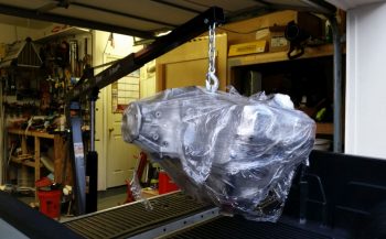
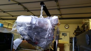
To be more specific, oil cooler decision round 2.  Unfortunately, I didn’t get it right the first time.  You see in my early thought processes I figured the Long-EZ was a well-developed design and folks had pretty much figured it out and it was all plug and play.  Boy, was off there!  Ask 12 Long-EZ builders how to do one thing and you’ll get 15 ways to do it…. with each one the exact right way to do it!

When it came time to acquire an oil cooler I just went with Mike Melvill’s choice –a 17-row cooler– because it was in fact his cowling that I was using. Makes sense, right?!  WRONG! I ordered my Airflow Systems 17-row 2008X oil cooler based on this info, but then when my knowledge matured on how the internal configuration was inside the cowling, I realized the 17-row 2008X was way too big.  In fact, I figure Mike M. must have turned it “sideways” (in comparison to it’s normal installation) to fit that monstrosity in there [I say “monstrosity” when in fact it’s only 1.6″ taller/longer than the 13-row 2006X… but of course we’re talking a Long-EZ here, and again, everything is TIGHT].

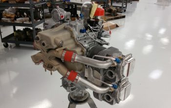
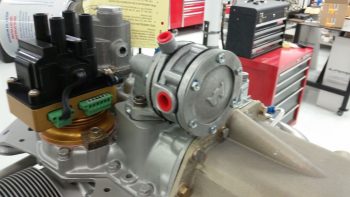
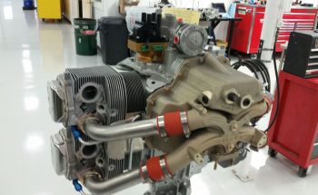
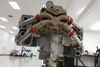
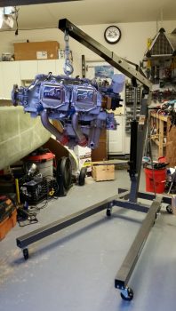
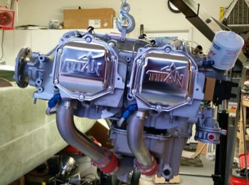
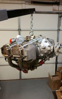
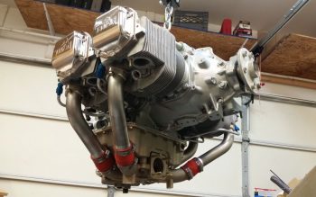
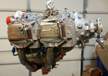
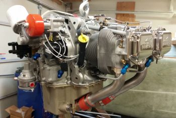
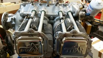
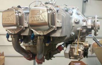
I had kept ahold of the 17-row 2008X because I had planned to run ECi’s tapered fin cylinders which, while cutting a few pounds off the engine, also, by their very design, had less cooling surface area.  However, after some discussion with my engine builder I decided to go a more traditional route (for increased maintainability, cooling and building ease while reducing cost for future overhauls/emergency replacement if stuck in Podunk nowhere) and install standard cylinders with the higher compression pistons…. again, 9.3:1 compression.

With my new cylinders on the engine I decided once and for all to finalize my oil cooler selection… again, although I had the 17-row 2008X.  I engaged Bill Genevro, Managing Director of Airflow Systems to go over my engine oil cooling requirements again (BTW, I’ve had fellow Canardians inquire why I went this route vs. the ever venerable Stewart-Warner cooler.  Well, Air Systems was recommended to me by a couple different sources associated with the Red Bull racing team.  That, and honestly… for half the price out the door, I just wasn’t yet prepared to bow down to the altar of Stewart-Warner).

I asked Bill the following:
A) If the 13-row would work in my configuration? (a bunch of spec emails ensued), then after the specs supported it (Bill said it would work fine, but he would have preferred that I still use a 15-row…. but I see so many O-320s using 9-rows, that I don’t think I’m off the mark.  In fact, just for some perspective, the 2006X oil cooler is listed for -360 and -540 motors, so it’s not a wilting flower in its own right.)
B) If I could swap out the bigger oil cooler for one two sizes smaller? … he said I could.

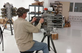
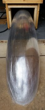
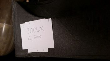
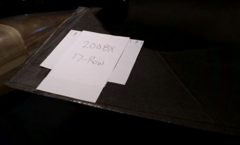
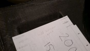
Before I fired off the 2008X out to Airflow Systems in California for a swap for the 2006X, I made up some paper cutouts of these 3 biggest oil coolers (17, 15, 13 rows) to test them out on my lower cowling, which has a nifty spot prepped and molded in it that just needs to be cut out for the oil cooler.

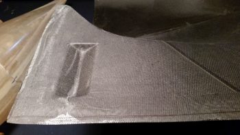
The smallest 13-row oil cooler, was –not surprisingly– a near-perfect fit.

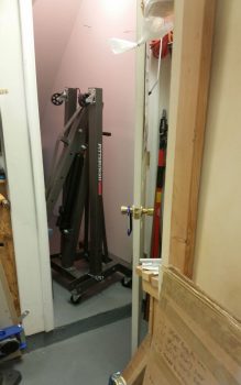
Here’s another shot so that you can better tell where I’m situated on the lower engine cowling: the forward left corner.

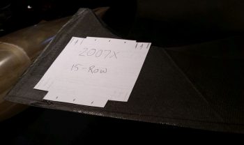
The 17-row 2007X wasn’t too bad, but it was starting to overhang out over what will be the air scoop for my Berkut-style armpit intakes.

I didn’t do a full separate paper cutout of the 17-row 2008X, just the center part which has the biggest footprint.  As you can see it goes right up to the left edge of the lower cowling. This could present an issue in that I don’t know yet where the exact left edge of the cowling is located since it may very well need to be trimmed to fit properly.

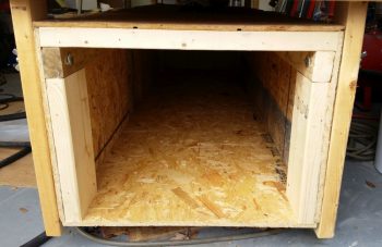
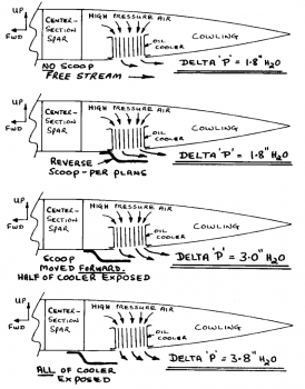
If you’re wondering, what is that indentation on the engine cowling? So did I for a couple years (remember, I bought my cowlings at the VERY beginning of my build).  Mike Melvill was quite clever in adding this to his cowling plug in that it’s the air scoop that hangs down in the airstream at the front of the oil cooler opening in the cowling (see two pics below).  As Dick Rutan found out in his tests for oil cooling on the Voyager, configuring the oil cooler opening in this fashion more than doubles the Delta ‘P’ from 1.8 H2O with just an opening to 3.8 H2O with this scoop preceding the oil cooler opening.

Now, I just had a lengthy and informative conversation with Joe Coraggio the other day, and something Joe said in regards to weight reduction really resonated with me.  Joe relayed that he had in fact made his cowlings from scratch out of Carbon Fiber, but that in the ensuing mods and redos on the cowling construction, which then mandated a bit more filler here and there, that his cowlings actually turned out to be pretty much the same weight as stock E-glass cowlings.  Not bad, and definitely better than if he had started with just E-glass, but it gave me a huge lesson learned: Don’t modify the cowlings unless absolutely necessary! I mention this because Mike Melvill was able to cut the weight of the original E-glass cowlings down by over half on his carbon fiber cowlings, which I now have a set of… the one last thing I want/need to do is start mucking around with them and end up in Joe’s situation (I thank Joe for being honest and frank about his build adventures, and sharing with me and others to allow us to optimize our own builds…. thanks Joe!)

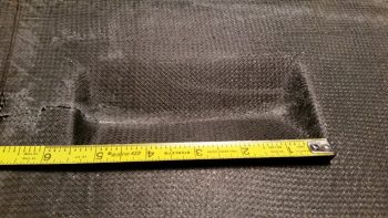
With all that in mind, I measured the width of the pre-molded oil cooler scoop on my lower cowling: 5.5 inches.

In addition to my discussion with Joe, I of course went back and reviewed my notes on oil cooling before spending any time, energy and money sending my 2008X oil cooler to be swapped out with a 2006X.  The last thing I wanted to do was burn more time and money on something that I may have overlooked, or worse yet, discovered years ago and simply forgot in the present day only to revert back to a previous less-than-optimized decision (happens way too many times in an extended build like this… maddening!).

I reread that so many builders state that the place to put the oil cooler is simply just below the alternator and starter so that the air exits with the exiting engine cooling air.  Probably not a bad place at all to put it, and it appears to have worked for many.  However, the criticism of the “plans” position prior to these builders/owners swapping their oil cooler position is often unfounded or misplaced (IMO) since I’ve noted how in so many of these cases they simple disregarded the findings that Dick Rutan discovered in prepping his oil cooling system for an around-the-world flight in the Voyager aircraft.  Yes, it may be a bit counterintuitive, and I’m sure there is some credence to the ever-present drag argument on this design, but personally I’m not going to argue with Mike Melvill or Dick Rutan, who both have flown this oil cooler design around the world . . . 3 times!!  If you think I’m nearly name-dropping, check this out:

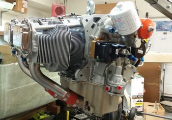
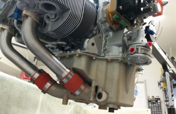
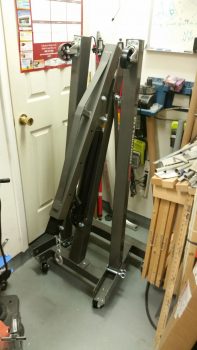
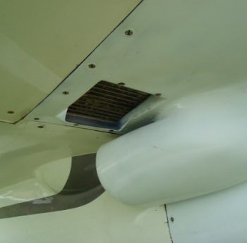
Here’s a real-world example of this oil cooler configuration on Mike Melvill’s Long-EZ.  You can see here that Mike did in fact turn his oil cooler so that the oil lines enter in through the top of the oil cooler facing forward vs the top of the oil cooler facing inboard towards the engine (right), the latter being how I’ve seen this configuration on the majority of canards. My configuration –again, the latter– allows for significantly shorter oil lines.  In addition, there’s no cooler body overhang above the air intake scoop.  Of course final install will be mandated by the final configuration of the engine situated within the cowling, so at this point I’m still technically in the planning (e.g. prognostication) stage.

Ok, so with my overarching goal of get this bird in the air combined with my self-ascribed mandates to “do no damage” in not messing about with cowling redesigns… and don’t change a design that works (i.e. this oil cooler position/configuration), my final check was to assess the actual cooling area of each oil cooler in regards to the pre-molded oil cooler scoop.

By this point the 17-row 2008X was a clear No-Go.  I then checked the 13-row 2006X and the actual airflow area width was spot-on with my pre-molded oil cooler scoop width of 5.5″.

As you can see, the 15-row 2007X’s (which honestly I was leaning towards “making it fit”) actual airflow area width was just too wide compared to my 5.5″ pre-molded oil cooler scoop width and would require a COWLING MODIFICATION which as I’ve stated above is in the just-say-no category.

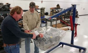
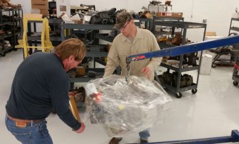
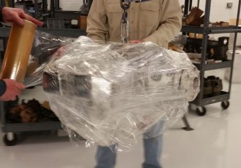
So, the 2006X was the clear winner, and with that I relabeled the box and sent the 2008X back to Airflow Systems this afternoon.

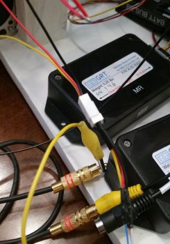
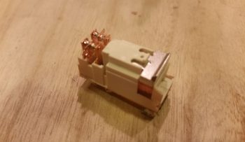
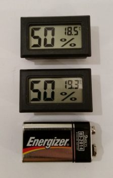
Upon returning home I checked my mail and lo & behold, the long lost humidity sensors/ meters for my engine dehydrator system finally arrived.  They’re a bit off in temp reading –which I don’t really care about– but in the house they are spot-on regarding their humidity readings.  As you can also see by the 9V battery that I included for size reference, these meters are quite small.

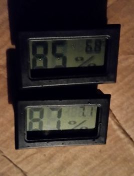
I checked the weather online and saw that the humidity was rated at 88% at Mount Vernon, a few miles from here.  So, I took my humidity meters out on the deck and left them there for a good hour before remembering that they were out there.  I snapped this pic an hour after the 88% report and again, a few miles away from the reported site (not expecting them to be exact either).  These are fairly close and really in line with what I read about these meters (in that with high and low extremes they may stray more from the actual humidity vs midrange where the reading tends to be closer to actual).

Regardless, they’ll definitely do for what I need in my engine dehydrator.  Good stuff!

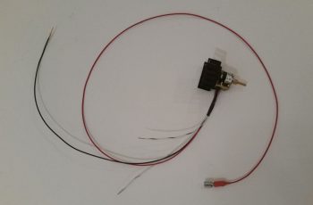
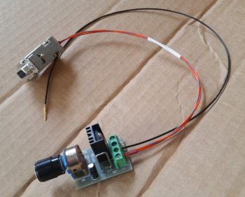
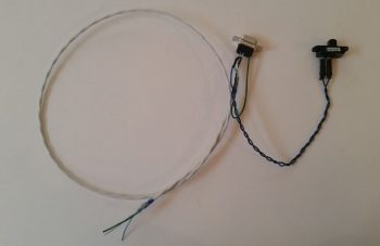
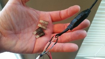
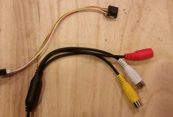
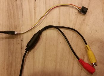
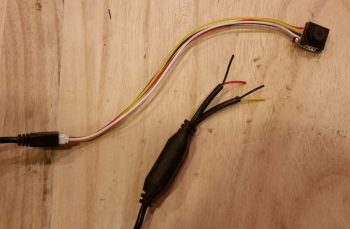
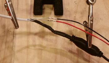
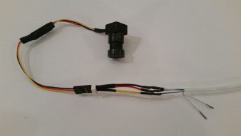
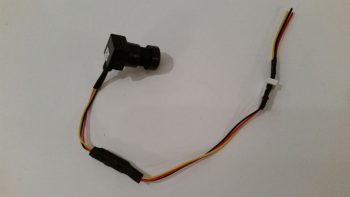
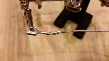
On my venture out this afternoon to mail off my 2008X oil cooler, I ran an errand for a friend of mine who asked if I could pick up a FitBit at a local vendor for her daughter and ship it to them.  Well, the place I went to pick it up was a huge computer parts warehouse which serendipitously had the cable lead for my topside 5V video camera.  Here I’ve cut the lead and will solder it onto the end of the 5x 22AWG-wire cable that I picked up from Stein.

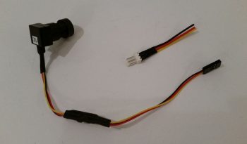
Here’s the lead terminals connected.  Again, this is the topside camera that will be mounted in the pilot’s headrest and face aft towards the engine.

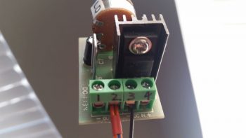
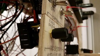
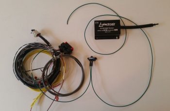
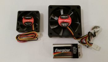
In addition, I kicked myself for having submitted an order to Mouser for the new SD-8 DPDT relay but once again forgetting to order the cooling/exhaust fans that B&C highly recommends for the SD-8 voltage regulator.  Since the finned/air cooled Electroair EI control unit is mere inches away from the SD-8 voltage regulator, not to mention the heat sinked SD-8 bridge rectifier, I decided to kill 3 birds with one small cooling fan attached to the side of the D-Deck/GIB headrest housing.

As you probably surmised, the larger fan is for cooling with external air and the smaller fan is an exiting warmer air exhaust fan.

With all my assessing, shopping and shipping shenanigans completed, I then got busy on the GIB heated seat warmer (I should note that on my adventures I actually found some thin diameter Rosin-core electrical solder at Home Depot…. yeah!).

I started out by replacing the seat warmer unit’s ground wire by soldering in a length of Tefzel wire.

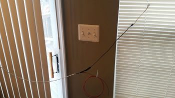
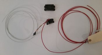
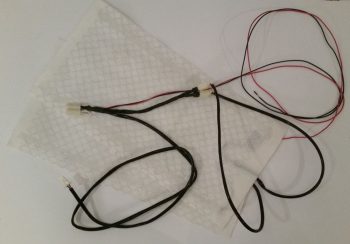
I then went down to the shop and measured out the distance from the heated seat warmer relay to the GIB seat “crease.”  Obviously, this seat warmer will require much lengthier leads going aft than the front seat warmer.  In fact, since the length of these 4 separate leads is over 6 feet long each, I upped the wire diameter for each lead to 18 AWG just to be on the safe side (20AWG would certainly have worked ok but since these leads are for heating elements with steady state current draw, I wanted to be on the “clearly safe” side of the equation, thus the rational for upping the gauge to 18AWG).

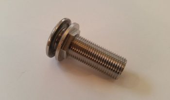
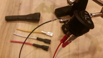
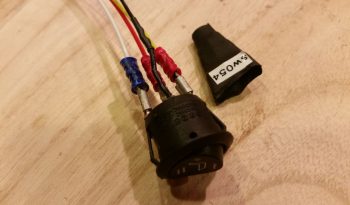
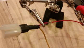
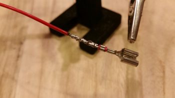
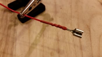
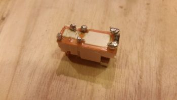
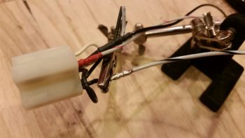
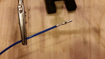
Again, just as on the front seat warmer I repurposed the locking PIDG Fast-ON tab by attaching the 18AWG power lead to it.

I then solder spliced the 18AWG power lead to the Fast-ON terminal.

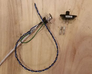
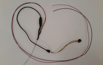
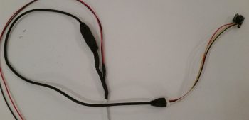
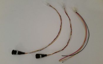
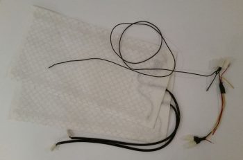
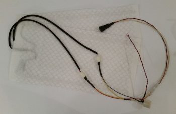
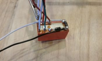
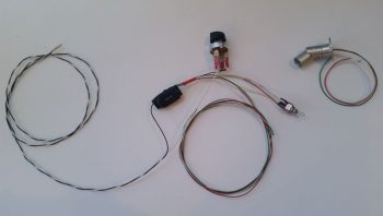
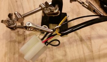
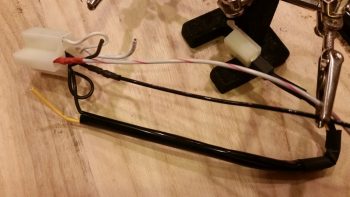
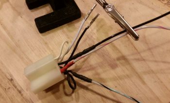
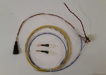
I then grabbed an interim shot of the GIB seat warmer wiring harness with the main ground lead and the seat warmer power feed wires replaced with new Tefzel wiring.

The thick black cable on the bottom is a feed to one of the 2 seat warming pads…

Which I then lopped off to leave just a stub of the black ground return wire remaining.

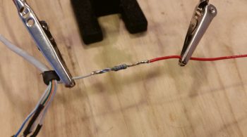
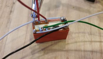
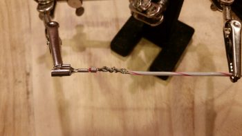
I then stripped the black ground return wire to prep it for splicing to the new 18AWG white with black stripe Tefzel replacement wire.

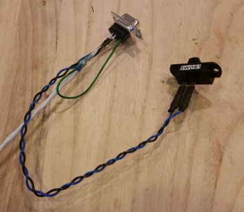
I then soldered the new 18AWG white with black stripe Tefzel replacement wire to the short length of the black ground return wire.

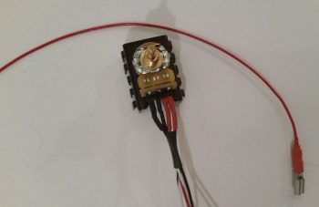
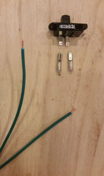
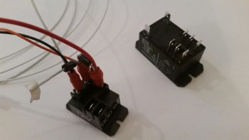
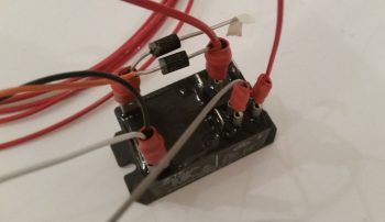
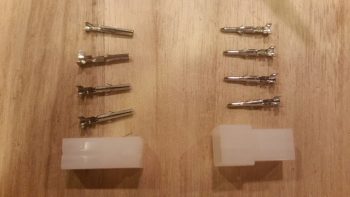
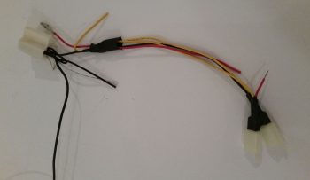
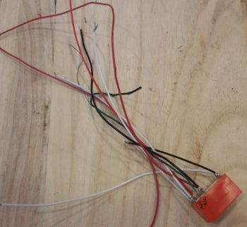
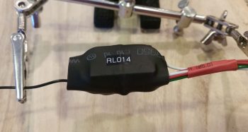
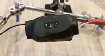
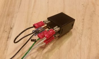
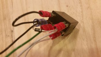
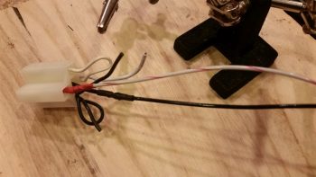
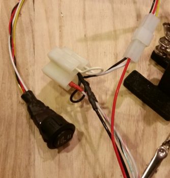
I then terminated the white and black switch wires with Mini-Molex sockets.  Not sure if I mentioned this last night, but the connectors coming out of each relay for the switches are reversed between the front and aft seat warmers, so there’s no way to get the switches mixed up since they physically cannot connect to the wrong seat warmer relay.

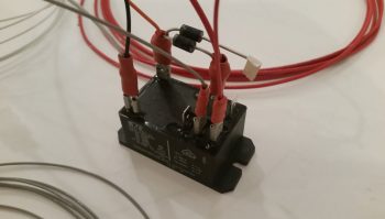
I then terminated the main system power wire (red) with a Mini-Molex socket and snapped it into the switch connector block.

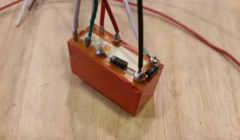
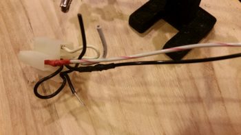
Again, I’m being a bit cautious here in my wiring selection, so knowing that 18AWG is a tad robust for the job, I only upped the wire size of the blue wire –that connects the yellow power leads together for a single lead into the switch connector block– to 16AWG.  BTW, these yellow leads are the other side of the white/red and white/black seat warming pad power leads (situated in pairs, with lower seat warmer: white/red + yellow  / upper seat warmer: white/black + yellow).

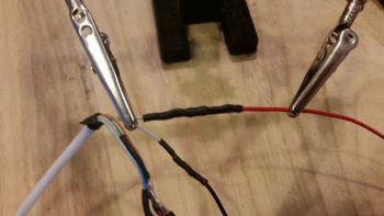
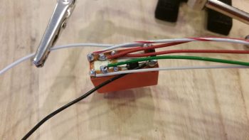
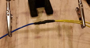
I then soldered the blue 16AWG lead to the 2 yellow 18AWG leads.

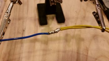
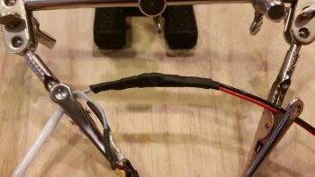
And then covered the solder splice with heat shrink.

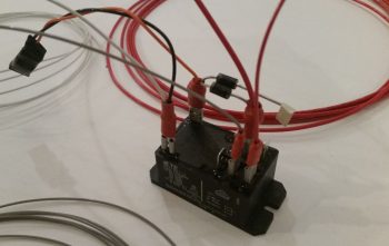
I then terminated the end of the blue wire with a Mini-Molex connector.

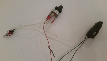
Since I am once again out of wire labels, and for these long-run wire leads I need them to be labeled, I’m holding off on the last task of soldering in the seat warming pad connectors until I can get the wires labeled (Point of note: my somewhat new requirement on wire labeling is that if you can see the components with the wire clearly running between the two components, I’m not overly concerned about affixing a label on the wire since it’s clear what it goes to).

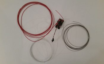
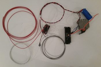
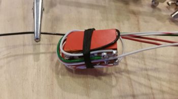
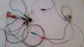
In addition, I weighed what is in the pic below and was actually pleased to find that even with these very long wire runs I am just a HAIR over the original wiring harness weight: 4.05 oz stock weight vs. 4.25 oz after Tefzel wire swap out.  A slight Δ of 0.20 oz more for a lot more wire… not bad.

The weather is forecasted to be in the 40s tomorrow, and not overly warm for the next week or so.  As you can imagine, I’m going to stick with these incredibly MUNDANE (read: UGH!) electrical system tasks until the weather seriously improves enough to allow for sustained shop work.


Chapter 22 – Front seat warmer rewire

Today was another heavy research day… I keep having new information serendipitously presented to me via FaceBook, etc. ….  then I ask a question, discussions ensue, and I find myself trying to finalize various configurations on my build (not bad, but often not my intent).  Today it was specifically regarding firewall cable pass-thrus.  Yesterday it was information that Chris Randall shared on FB about wiring up the EIS4000.  I’m grateful for the information to be certain, but these little heading changes do eat up some time.

I finally got to the actual build early this evening.  All told I spent well over 4 hours rewiring the front seat warmer system with Tefzel wire vs the automotive wire it came with. There were a few places I didn’t swap out the wiring since the amount of wire that would have been removed (relay jack jumpers) or the configuration just wasn’t worth the effort.  So, all in all I’d say I ended removing and replacing about 70% of the automotive wiring with the Tefzel.  Not bad.  And, in the process reduced the wiring harness weight by over 2 oz. Nothing to shout from the rooftops of course, but at least I didn’t ADD weight!

I started out by focusing on the front seat warmer switch rewiring.  I did replace the PIDG Fast-ON terminals on the switch since I wanted the higher grade Fast-ONs, plus it was just easier and faster.  Moreover, I’m getting critically low on my fine wire solder (the good stuff!).

Here’s the front seat warmer switch after I rewired it with Tefzel wire and new terminals.

For the connector that goes on the end of the switch’s 4-wire harness, I chose to go with a 4-position Mini-Molex connector.  As I mention often, I’m not a huge fan of Molex, but this fits the bill for a lightweight, easily built connector on a non-critical component.

I finished the front seat warmer switch conversion, including the attachment of the Mini-Molex connector, and then I knocked out the GIB seat warmer switch conversion as well. The wire bundle on the far right is one of the original switch wiring harnesses.

Here’s how the front seat warmer assembly looks (minus the switch harness) as it comes from the factory.

Here I’ve removed a couple of the larger unneeded sub-harnesses, and am working on the main lead wire bundles to the two separate heating pads (seat bottom and seat back).

Here’s a closer shot of the main area of the wiring harness.  The white connector in the upper left corner will attach to the relay that is already mounted in the fuselage.  The two connectors in the lower right attach to the actual seat warming pads.

I then rewired the front seat warmer harness with Tefzel wiring.  Since the Fast-ON connectors in the relay jack have locking tabs, I figured it would just be easier to cut away nearly all the automotive wire and solder in almost completely new segments of Tefzel wire.

I then soldered the power wire to the Fast-ON tab.

And then covered it with heat shrink.

Here’s the new & improved front seat warmer setup with the majority of the wiring swapped out for the much more robust and safer Tefzel wiring.  Again, it also reduced the overall weight by a couple of ounces…. not bad.

I didn’t realize I was so low on solder until I nearly ran out this evening. I’ll order some more solder in the next day or so, but that will help facilitate my transition back into shop mode.


Chapter 22 – GIB Cabin Lights

I started out today with a goal to complete 2 things: 1) The GIB cabin map & floor lighting relay circuit wiring and 2) the front seat warmer rewiring to replace all the auto-grade wiring with Tefzel wiring.  Well, as things go on this build, I was only able to complete goal #1… but complete it I did (with a video even!) so that’s something.

I started out by reviewing the wiring circuit for the GIB cabin map & floor lighting relay, which is relay #14.  After re-familiarizing myself with how it all goes, I got some wires and diodes and got busy.

Here’s how it looked when I started.

I then added a couple of diodes, one as the flyback diode across the coils and the other for the ground lead to common.

As I was looking for a fairly lengthy ground wire I ran across a twisted pair of 22 AWG white and black wires about 5 ft long that I had picked up from Stein at some point. Knowing that I was running low on opportunities to use this kind of pre-configured stuff I quickly pressed it into service.

A point of note, however, only the black ground wire below is from the twisted pair.  The white wire is about 9″ long and goes to the white light/red light selector switch.

I then added in the green and white control wires that are used to power either the white or red LED lights on the map light (an either/or setup).

I then finished soldering all the other wires onto the relay tabs.

I then wrapped the wires around the relay and tied them with cable lace to ensure the wires were secured in place.

I then covered all that with a 1″ diameter piece of heat shrink, and finished off the relay build with a couple of labels.  Here’s side A and side B.

And here’s the whole GIB cabin map & floor lighting relay circuit wiring with the map light added into the pic. Since the floor lights are already mounted into the fuselage I couldn’t/ didn’t add them here.

Then I ran into an issue…. took me a while and some in-depth step-by-step troubleshooting to first ascertain that I hadn’t wired anything incorrectly, then next re-evaltuate my circuit to ensure I actually designed it correctly, then finally I was specifically able to narrow down my issue to the relay coil.  It was just spotty and unreliable…. for unknown reasons (to me anyway) it would work here, but not there.

I then slightly modified the circuit and used a SPDT automotive relay that I had on hand and it worked a treat (for you Dave!) . . . so I yanked the “old” relay, finalized the new circuit design, did a final test, and then wired up the new relay.

Here’s a couple shots of the new 12V SPDT automotive relay that I swapped out the “old” DPDT relay with (I’m running low on solder and honestly didn’t want to take the time, so I used PIDG Fast-ON terminals):

After I finished wiring up the new relay, I tested out the circuit.  It looked good so I figured I would try out my Christmas present from Marco: a tripod for taking NON-bouncy videos (the wimp said my videos were making him seasick…. man up! ha!).  So here it is:

With another fairly thorough test completed during the video taping, I then cut another piece of 1″ diameter heat shrink, wrapped the relay wire leads to secure them, then heat shrank it all.  Of course I then re-labled my new relay #14.

I snapped the cover off the “old” relay to see if I could see any damage or scorch marks in case I had fried it somehow (I did fry a diode about 6 months back, but the relay seemed fine…. I guess not).

In addition to getting the GIB cabin map & floor lighting relay wired up, I also spoke with Bill at Airflow Systems to see about the possibility of swapping out my 2008X 17-row oil cooler for a 2006X 13-row oil cooler.  Since I’m not using tapered cylinders on my IOX-340S engine now and my compression is not super high (9.3:1) then I’m going to make my life easier (we discussed the specs and oil cooling requirements of course) when it comes to oil cooler placement and installation by picking up an oil cooler that’s about 1.5″ less in length than I have currently.  Thus, I plan on sending my 2008X in for replacement here within the next week.

As for build tasks, the weather is getting warmer . . . during the day.  But for the next 7-10 days we still have dips down into the 30s at night.  I do plan on getting into the shop, but I will get some more of these electrical system tasks knocked out during the next couple weeks as well.


I’m here . . . still kicking!

As I mentioned in my update post, since I’ve been back I’ve been swamped with a number of “maintenance” type tasks both on the build and in my personal life.

Starting out, normally when I head south for a few days I take an hour or so each night and update my website by parsing out all my blog posts into the respective build log chapters. Well, as you may have noticed, with all the cold weather we’ve been having here I have been focusing mainly on the electrical system.  Ok, so when I tried to get into my electrical system web page it came back with a fatal error since the size allocation for the page wasn’t enough to edit it!  In addition, WordPress had just come out with another version update and I wanted a good site backup before I did the WordPress update.  In short, it was just too much of a hassle for me to mess around with while I was gone.

When I got back I researched what I needed to do to update the page size allocation limit. I logged into the server, did a site backup and then proceeded to hack into some root directory files to allow me to up the page size allocation limit.  Once that was done, I could then finally get into my Chapter 22 – Electrical System page to edit it.  My edit actually consisted of taking a good amount of the content and parsing it out to other pages, some already existing, and a number that I just created.  Once I did that, I then proceeded to do my normal updates.  To be certain, all this together was no small feat (since I had been remiss in doing any updates in the past 2 months) and all told it took over 12 hours, over a couple days to knock out.  Yes, it’s not specific airplane building stuff, but it should be the last major reorg of my site before this plane is flying.

In addition, since I’ve been back, I also updated my GRT Mini-X’s software and downloaded all the new Seattle Avionics chart and approach plate data.  Plus, I updated a few checklists on the HXr.

As you can see, it’s been a very data-centric past few days.  But with all that behind me, I updated my task/to-do list and I’m ready to get to it.

BTW, I spoke with my engine guy and I we should be figuring out when to finish this darn thing in next week or two.

Finally, the weather should be getting warmer here in the next week, so I will start slowly getting back into shop mode.  There are some electrical tasks I want to finish up, but I’ll probably work those for a few days and then start multitasking between those and shop tasks.