Chapter 23 – RAM can SCEET bracket

Starting off, here’s a pic of my preferred location for mounting the fuel injection flow divider on the bottom side of the engine: the underside engine aft mounting flat.  Notice the engine case notch just forward of the flat, which ends where I’m pointing at with a screwdriver.  Any point forward of the screwdriver begets interference problems between bracket and engine case.

I then tested out the fit of the Version 4 bracket.  It fit fine, but I decided to round the corners significantly to remove unneeded bracket material: aka weight.

I had been looking at various metals to use out of curiosity.  Something a bit stronger than the ‘ol standard 6061 aluminum, but other metals like stainless steel meant a bit trickier machining while other aluminums like 2024 or 7075 meant poorer corrosion resistance (read: Alodine required).  Thus I simply planned for the ubiquitous 1/4″ thick 6061 T6 for Version 5 and kicked off the 3D print of that.

I then sliced off another 1/4″ off the front attach point of the air induction 180º tube and reattached it with duct tape to the mock cardboard mounting plate.

I then remounted the cowling and checked the latest clearance between the induction tube and the bottom inside cowling.  Interesting… just as I had hypothesized, the shorter the attach point of the tube the more it was driving down the entire tube assembly towards the cowling.  It makes sense since the tube angle is much more significant than the drop angle of the cowling bottom moving forward.

This clearly means I need to start back at the beginning and do whatever tweaks I can do OTHER than shorten the original attach tube.  More to follow…

I then spent the rest of day testing out and dialing in the milling machine.  First off I tested my SuperFly facing tool on a block of wood.  It worked near-flawlessly.

I then tried it again on the rough edge of the scrap piece that I cut off of the 6061 block that I’ll use to machine the RAM air can SCEET tube adapter bracket.  The Superfly bit in a little more than I wanted it to, but that allowed me to tweak my post processing.

I then flipped the scrap piece 90º so that it was flat in the vise, just how the part stock will be.

I then again tested out the SuperFly facing tool on this scrap stock, and once again, it came out awesome… Taking about 0.005″ off the top surface, just enough to provide a beautiful near-mirror flat surface.

I then used the SuperFly to hit the front (interfacing) side of the RAM air can SCEET tube adapter bracket.  Part of the machining flow was to then drill 4 holes to mount the entire piece to a wood backing plate to machine it further.

Admittedly, dealing with the Fusion 360 updated software changes and not following my own task list, I failed to probe all the tool lengths and crashed my hole starter drill mill when it failed to clear the first hole coming out.  Thankfully this is aluminum and nothing was damaged except my pride.  About a 2.5″ diameter circle around the holes will be bored out from the inside to create the air pass through… so all that material encompassing the crashed hole will get removed anyway (thankfully!).

I then inverted the stock and mounted it to my 3/4″ plywood base with two 3/16″ bolts and two #3 screws.

All this testing and prep took a good bit of time, so I plan to finish the machining tomorrow.

Chapter 23 – Spider wrangling

My intended goal for the day was to finalize the configuration of the air induction tube attached to the aft side of the fuel injection servo, but that didn’t happen.

First off, I will note that although I have a lot of pics in this post of the fuel injection flow divider mounting bracket versions and test installs, I really didn’t spend that much time working on it.

I started off spending about 15 minutes installing my modified design of the fuel injection flow divider mounting bracket.

This bracket version flushed out a couple of issues right off the bat.  First, in the pic above note the red arrow which is where the bracket is pressed up against the bottom surface of the engine.  The bracket is too long/wide and needs to be shortened/narrowed to move it aft on the motor (right in the pic).

Also, the third bolt hole (aft/right side) was contaminated with paint or something, and I had to use a tap to try to clear it out.  I got about 3/8″ in but hit something that was making it impossible, with the access I had at this point, to get enough torque on the tap to break through.  Thus, since this is not the main priority I simply punted and decided to go with the forward (left side) two bolts and press on.

Today was the second of two beautiful days with warmer weather in the low 60’s.  I decided to get some outside household tasks knocked out, which burned up a few good hours.  But while it was still light out (and warm!) I took the opportunity to cut my recently delivered block of 6061 aluminum that I ordered for the RAM air can SCEET tubing attachment adapter bracket.

This chunk of 6061 is 1″ thick x 4″ x  6″.  The SCEET adapter bracket needs to be 4″ x 4″ square, so I’m going to trim down the long side to just over 4″ wide.

To be specific, I marked my cut line at just a hair over 4″, at 4.07″.  Normally I would use my horizontal band saw to cut this but it is not cutting straight lines and I didn’t feel like spending an hour or two messing around with it to get it aligned properly… which I probably should have, but I’m feeling way behind the power curve time-wise with all the engine/cowling challenges that I’m currently dealing with.  So I used my chop saw, which I know cuts straight… albeit the blade has a much wider kerf.

Here’s the end result of my 6061 stock trimming.  The final width turned out to be right around 4.093″ wide, just a wee bit wider than the cut line I marked.  Of course I’d much rather be 0.09″ over than under 4″… so pretty darn good in my book!

Pic #2 (right) shows the cut end… a little rough but not bad.  All but a ~1/4″ of this edge will be removed anyway!

Again, I spent maybe 10 minutes tweaking my Fusion 360 CAD file to create the latest mod, Version 3, of the fuel flow spider mounting bracket… which I then kicked off the 3D print to be whirring away while I trimmed the 6061 stock above.

I pulled the old Version 2 bracket off and put the new Version 3 bracket on… As Maxwell Smart (most of you are hopefully “mature” enough to remember him) from “Get Smart” used to say, “Missed it by that much!

Again, the bracket is encroaching on that one edge on the bottom center line of the engine by literally around 1/16″ … so close!  I’m using the yellow-tipped pointer to ID the area of interference.

Here’s a wider angle shot to show how the fuel flow divider will look installed on the underside of the engine (IF and when I choose to move it down there).

The time lapse between the above pic and the one below is about 4-5 hours.  I cut more wood outside on the table saw for the mounting base to machine the 6061 aluminum stock that will be the RAM air can SCEET tubing attachment adapter bracket.

I then went to do some test cuts to ensure the alignment was good on the milling machine when I hit a wall regarding the Fusion 360 CAM post processing software.  Apparently at some point getting back online and starting to use my Fusion 360 software involved them updating my software, which changed the parameters and profile of my milling machine, lathe and plasma cutting table.

Apparently their lovely “upgrades” and “improvements” hit after I machined the wood end plugs for the rudder return springs.  This evening I couldn’t get the Fusion 360 CAM software to produce the post processing files I need to tell the milling machine’s Acorn control software how to machine the part.  I finally got some post processing files out of it, but they still aren’t 100% and seamless as before.

It is probably impossible to convey the intensity or level of my being pissed off.  Having worked in the IT/communications field for half my military career, I dealt with geeks all the time wanting to change things “for the better” with no underlying driving requirements… which it seems this is exactly what the cell phone, computer OS and these Fusion 360 geek assholes seem to do with reckless abandon.  My cell phone camera being a perfect example… if it works, don’t mess with it!

Rant over… partially.

I then tweaked the fuel flow divider mounting bracket by moving the bolt mounting holes forward (to the left) by 0.15″.  I then trimmed the right edge by the same 0.15″.

Perhaps you noticed that my last two 3D prints look much better than the previous ones, with the print lines running diagonally on the part vs straight across? That I’m not getting any edges curling up?  This is due to me updating my Cura slicing software a while back and it wiping out all my slicing profiles for PETG and PLA.  Yep, more geeks at work… helping “improve” things.

Well, my fault I guess for updating the software.  Of course I have screenshots of my profiles, but there are a dozen screens and countless parameters… so I am slowly dialing in my old parameters that actually worked.  Much as I am in the process of doing with Fusion 360. And to new “improved” versions of these softwares and their updates?  From here on out I need to just simply learn to say “No!” (although Fusion 360 is mostly cloud based so no opting out).

. . . . I warned you!  I’m pissed.

Tomorrow I’ll continue to work on dialing in my CAM post processing software to get the RAM air can SCEET adapter machined.  Then onto finalizing my air induction tube to get it glassed and mounted as well.

Chapter 23 – Induct, induct, induct

I had to run some errands this morning so I grabbed some hardware for the fuel injection flow divider and mounting bracket.

After I returned home, I then mounted the fuel flow divider to the mounting bracket with 10-24 screws.

With the bottom cowling off, I then went to test mount/fit the 3D-printed fuel flow divider and bracket assembly.  Immediately I realized that in my rush job to model the mounting bracket up in CAD that I had messed up the dimensions for the actual attach portion of the bracket, which should have been a bit wider than the round portion up higher where the actual flow divider attaches.  With the bracket’s bolt holes misaligned, I went ahead and mounted it using the center hole.

The setup was definitely good enough though to allow me to assess the possible mounting of the fuel injection flow divider on the underside of the engine.  I decided that I would want the flow divider as close to the original fuselage station as it is mounted up top.  Clearly as far forward would be better for mitigating any negative aft CG impact.  Plus, the more equidistant and centrally located the flow divider should translate into shorter lengths of fuel injection lines required.

Jumping ahead a few hours, I spent about 10 minutes revising my fuel injection flow divider mounting bracket to offset the flow divider forward while still using the same engine mounting pad.  I figured two hefty 5/16″ bolts should hold it fine, so I eliminated the center bolt hole, facilitating easier install, less cost and less weight.  Tomorrow I’ll check out this new design.

I then got onto trimming and testing out Version 4 of my air induction 180º intake tube. After looking at it for a good little bit, I decided to trim the front tube at the intersection with the fuel injection aft face at a slight angle, to get the in-rushing air to enter in a bit straighter.  I cut a line with 5/32″ off the top and 1/4″ off the bottom.

I then remounted the Version 4 intake tube onto the aft face of the FI servo.

And once again remounted the bottom cowling.  As I suspected, I really didn’t get much from my trim.  I noted with the angle that the tube attaches to the aft face of the servo, I have 2 opposing actions going on when I trim the front of the tube to push the entire assembly forward:  A) Trimming/moving the tube forward pushes further forward in the “chute” that is the bottom of the cowling, that drops down as it goes forward.  That’s a good thing, but the drop is a bit shallow.

However, action B) is that with the angle of the top part of intake tube curving somewhat sharply upwards as it goes aft, when I trim the front of it to push the entire assembly forward, I’m also dropping it down a hair as well.

So the question is, which action is making the most difference and winning out?

Using my 0.27″ cardboard spacer, I could see it was definitely easier to slide in and out under the cardboard bottom edge, but that really only gives me more clearance of maybe 0.01″ to max maybe 0.02″ more.

The good news is that my air is entering the servo a bit straighter, but at slightly less total straight distance, and I didn’t really gain much as far as clearance.  I’ll have to ponder on this a lot more to see if any panaceas jump out at me.

Meanwhile, I received my respective ACS and McMaster-Carr orders today, which allowed me to assembly the components for my Sniffle Valve assembly.  Years ago, when my engine builder warned me about installing a Sniffle Valve, I did some research to get as much info as I could.  I ran across Matt’s RV-7 build blog and noted how he angled his Sniffle Valve to get around an exhaust pipe.

Well, I may need to angle mine to get around the 2.5″ SCEET duct that will connect the RAM air can to the fuel injection servo.  Regardless if I angle it or not, I will need to attach a drain tube to it to exit out the bottom of the cowling.

I started by gathering up all my newly acquired components that will make up the Sniffle Valve assembly (left pic).  And then used my Dremel Tool to remove and shape a good bit of the material on the threaded barb fitting to allow it to fit inside the AN -4D fitting nut (right pic).

Here are all the Sniffle Valve component parts assembled.

I then test mounted the Sniffle Valve assembly into its port on the bottom of the cold air plenum.  Again, if there is enough clearance between the Sniffle Valve and the SCEET tubing, I may not need the 45º street elbow, but better to have it on hand just in case.

This shot might give a better perspective of how the Sniffle Valve can be angled to avoid the SCEET induction air tube.

I’ll further note that I also just received a barbed brass “Y” fitting that will tie the Sniffle valve runoff tube to the mechanical fuel pump overflow drain tube to then allow me to have only a single tube exiting out the bottom of the lower cowling/firewall flange.

I’ll continue working the air induction system and engine components install tomorrow.

Chapter 23 – Induction shenanigans

I started off today by re-mounting the trimmed cardboard air induction tube mockup in place on the aft cardboard plate already in place on the aft face of the fuel injection servo.  Note that pic #2 shows the targeted mounting flat for the probable move of the fuel injection flow divider to the underside of the engine.

I then put the bottom cowling back on to check the clearance between my cardboard air induction tube mockup and the inside bottom of the cowling.

The good news is that there is actual clearance, the not so great news is that the clearance I got with cardboard tube mockup version #2 was just a hair over 1/8″.

Yep, a game of compromises . . . .

I completely redrew and made up another cardboard mockup for the cold air induction tube for my 180º turnaround into the fuel injection servo.  I cut another 3/16″ off the tube at the entrance into the FI servo, pushing the entire tube forward 3/16″.  Trimming here helps since the bottom of the cowling slopes downward as it goes forward.

In addition, I reduced the radius of the curve by 0.08″ to 1.92″ vs. my original 2″ radius, which I copied from the Airflow Performance elbows bolted together.  Again, compromises.

I then reattached my new Version 3 air induction tube to the aft face of the FI servo.

You can see that the clearance between the bottom of the servo and the forward tube of this duct has been greatly reduced, albeit still acceptable.  You may be able to see that now the forward pointing part of this tube is significantly higher than the top edge of the RAM air can opening if you drew a straight line from the aft tube.  More on this below.

I then re-mounted the bottom cowling and checked the clearance.  The cardboard I’m using is 0.269″ thick, so round up for an easier 0.27″.  Clearly over double from what I got from the Version 2 mockup, but still a bit too close for comfort… at least for me.

My plan is to trim another 1/4″ off the tube at the attach point/aft face of the fuel injection servo to move the entire tube/duct forward 1/4″ as well.  This should get me hopefully another 0.03″ to 0.05″ in clearance.  Maybe just a scant more with the bottom slope of the cowling in its diverging from the bottom edge of the tube.  Understandably not much, but it still gives me just over 1.5″ of straight air going into the servo air intake entrance —albeit at an angle— and at the risk of repeating myself: I’ll take what I can get!

Clearly the next version of the mockup will be #4.  Hopefully this gets me acceptable clearance results that I can live with, focusing of course on the lower aft curve area.  To then smooth out the transition between the RAM air can and this air induction tube, I will most likely make up a Version 5 that has the front forward point part of the tube angled down a bit to be as much in line with the RAM air can opening as possible, while maintaining a good clearance with the bottom cowling.

As I was involved with my fun-with-cardboard arts and crafts shenanigans above, my 3D printer was busy creating a basic mockup that I had modeled up in Fusion 360 of my fuel injection flow divider.  I put the spec’d threaded mounting screw holes in it so I can attach it to the mounting bracket that I’m also creating.

Here is the real fuel distro “spider” next to my 3D printed version, which looks a bit bigger since it’s one solid color, but they are the same size.  I didn’t take any extra time to create the intricate features on the top, I just threw a cylindrical cap on top to represent the overall height of the flow divider.

As soon as the fuel distro spider came off the 3D printer, I kicked off the 3D print of my fuel flow divider engine mounting bracket and let it run.  Here’s the result.

I called it a bit of an early night and enjoyed a nice dinner Jess cooked up for us.  I’ll get back on the build tomorrow.  I will note that I’ll be out of town next week for almost the entire week on vacation, then back to it again after that.  January will be a very busy month for this build!

Chapter 23 – FI servo duct fitting

I started off today by transferring my paper 180º air induction tube and bracket drawing to a more 3D version of it in cardboard.  The bracket portion is very close to what the flat bracket portion will be that attaches to the aft face of the FI servo, while the flat cardboard mockup of the tube is of course to check vertical clearance… although I did also check width as well (down below).

I tried as best possible in these shots to capture the almost perfect alignment between the cardboard “tube” and the RAM air can inlet… although clearly with this distance a perfect alignment is not an absolute necessity.

One more shot from the aft side… my camera lens is offset, as this was meant to show everything in excellent alignment on the centerline.

I then mounted the bottom cowling… which thankfully I was able to get completely installed.  You can see a very slight deformation of the bottom of the cardboard tube mockup, about 1/16″ I’d guess.  Since this is at the aft end of the engine and cowling, I’d like a bare bones minimum of 3/8″ clearance, while 1/2″ would be even better.

It may be hard to see, but before removing the cardboard tube mockup, I made a Sharpie mark at the aft end to denote where the tube turned upwards on the aft side.

I then took a 2.5″ diameter tube I have on hand and placed it inside the bottom of the cowling with the edge resting on that Sharpie mark: to ensure I had clearance in all directions, but specifically left and right, for a 2.5″ diameter air duct tube.  As you can see, I do.

The mockup showed that some configuration tweaks were going to be needed, which means compromise on my requirements.  Reluctantly I trimmed a 1/2″ off the straight length portion of tube where it will attach to the aft face of the FI servo.  This now gives me only 2″ of straight air going into the servo vs 2.5″ … again, I have to take what I can get.

In addition, I also angled the tube at the entrance just a bit more to raise the entire duct up a bit.  This will be the last angle increase I do, and I probably should have stopped at just the 1/2″ trim in length.  But I’ll put this back on (tomorrow) and see how the clearance looks.

I then confirmed some dimensions on the aft face of my RAM air can where I’ll need an adapter to attach the 2.5″ SCEET tubing coming from the FI servo air duct tube above.  I modeled up the adapter in Fusion 360 CAD and grabbed a screen shot.  Now, I will point out that the final version will have chamfered corners, but that will be a subsequent milling operation so this is the first phase version of the SCEET tube mounting adapter.

Switching gears slightly . . .

I got a comment from Dave Adams, a very knowledgeable Canardian, on my last YouTube video build update where he advised me to consider mounting the fuel injection flow divider on the bottom (cold) side of the engine to ensure the fuel stays cool in the lines.  I get it.

But I had a some in-depth talks with Buly and my engine builder, who both had their spiders mounted up top, and neither had an issue with it up there over countless hours of operation. So now I really do want to know first hand what the difference is between running the fuel spider up top vs down below, but as I thought about remounting the fuel spider down below later on after the bird is flying, I pondered on what this would entail baffling-wise.

I don’t think the mechanics of moving the flow divider down below is all that crazy difficult, just time consuming (read: tedious) and a little pricey if different length stainless steel fuel injection lines are required.  However, again, the real issue I’m starting to see is maybe having to redo some baffling.  I’ll assess further.

Regardless, I went ahead and scoped out a good bit of the details of moving the fuel flow divider/spider down below.  I honestly don’t remember, and couldn’t find after a few minutes of Internet searches, what the 3-holed angled pad is on the aft underside of our engines (front side for tractor drivers), but that’s where I decided to mount the inverted fuel flow divider (ok to mount in this configuration per manual). And yes, my initial swag conveyed that at least 2 new fuel injection lines would need to be bought for relocating the spider down under, as well as some new hardware.

I mic’d up the dimensions of the this possible fuel spider new mounting pad as well as the fuel distro spider body and ginned up a mount in Fusion 360 CAD.

To be clear on where these CAD’d and machined adapters/brackets/mounts will go, I plopped them into the first pic from above.

Tomorrow will be round 2 of mocking up the 180º air induction tube to ensure that I’ve got the minimum clearance required.  Then I’ll start working on the best way to construct it to ensure a nice clean internal surface on the air duct tube.

Chapter 23 – Fuel Injection & More!

Merry Christmas and Happy Holidays everyone!

Over the last few days, besides getting ready for Christmas and truly enjoying this holiday (for what it really is!), I’ve been doing a lot of research on primarily my fuel injection system, but also a multitude of other engine components, including fuel system stuff too.  I’ve dropped a number of orders for fittings, more stainless steel hose, hardware, and aluminum and stainless steel for machining induction tube adapters, cable brackets, etc.

Today I finalized my Course Of Action (COA) assessment.  I found a critical error I made with labeling one of the Precision Airmotive diagrams in getting my throttle lever push-pull direction backwards.  Once caught and corrected, that pretty much nixed COA 3 —fuel injection servo facing forward as I had planned from very early on.

COA 1 has the FI servo facing forward as well, just inverted 180° from COA 3.  Since this puts most of the offset “mass” of the servo to the left and up high (clearly opposite of COA 3), it would require a spacer in between the two ~”90º” elbows to allow clearance for the topside -4 fitting (still no room for it on the bottom) and Sniffle Valve.

Using a spacer for COA 1 puts me right back as having a lot of the same issues as I was fighting with COA 3.  Worse, it really jacks up what little clearance I had —due to the contour of the bottom surface of the cold air plenum— for the top -4 fitting.  Moreover, the alignment between the fuel injection servo intake and the RAM air can exiting air is awful… off elevation-wise by over 2″ in a distance of about 5″ from face to face.

The bottom line is that both forward facing COA 1 and COA 3 are no-go’s.  That leaves me with only the aft-facing COA 2 as the last viable option.  Clearly I need to make this option work.

First up, my plan to buy my way out of work failed.  Unless I resort to some major surgery on the Air Performance air induction elbows, specifically the bottom one, then I’m once again left with no clearance with the bottom inside of the cowling.

To facilitate adding components and adapters, obviously the elbow mating flanges are square with threaded studs to attach to servos, filters, plenums, etc.  The squareness of the flange required for threaded studs and the area required to place a gasket for a nice airtight seal adds to a lot of the volume of these elbows.  Plus, let’s be honest in that they are a bit hefty at over 1.5 lbs. total… more than that once all the hardware is added.

By simply changing the shape of the bottom elbow to a comparatively thin-walled round tube, it would eliminate a lot of the lower clutter that cause the clearance issues with the inside bottom cowling.  Thus, using the same curve radius: 2″, I drew up a possible replacement for the combined elbow assembly.

I’ll note first that I wanted as much of a straight shot as possible entering the fuel injection servo to calm the air down and have it less turbulent as it enters the servo.  My limiting factor is going aft, where I will hit the wall —literally— since at 6.6″ aft of the servo face will be the aft lower baffle wall to seal off the hot vs cold side of the engine cooling air.

With a constant 2.5″ diameter duct and maintaining a 2″ minimum diameter curve, this gives me just a hair over 2.5″ of “straight” air prior to entering the servo… with one caveat: to get the entire ductwork up higher and off/away from the bottom cowling “floor,” I canted the straight segment up around 5º from the start.

I have to say that initially, this configuration looks fairly promising.  I dropped the bottom tubing going forward down from the servo plate 1″ to allow for clearance with the bottom port cover plug, but I do have wiggle room to scooch the entire duct up a bit if required.  Tomorrow I’ll make up a quasi-3D model of this duct, test it out on the servo and then check the clearance by mounting the bottom cowling.

Almost certainly more tweaks to follow …

In other news: off and on all day I’ve been playing around with locations to mount the external oil Verrnatherm (more research on that required) and the engine sensors.  With so little space for these components, it’s really driving me to minimize the use of “traditional” manifold blocks and simply go with 1/8″ NPT 3-way T-fittings, as here with the oil pressure sensors that were in a manifold that I’m chucking out in lieu of employing a more diminutive T-fitting.

I also assessed installation locations and configurations for the manifold pressure sensors block and the fuel pressure sensor.  This exercise resulted in a slew of Adel clamps, fittings and hardware being added to the “to-buy” list.

The long slog continues!

Chapter 23 – Fuel Injection Servo COAs

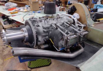
Yesterday, as a retired military officer, I spent a few hours doing what I was best trained to do: build a PowerPoint slide deck that covered the possible COAs, or “Courses of Action” for the possible configurations for installing the fuel injection servo. Of course it was replete with pros and cons for each one, as well as specific install requirements for each configuration as well.  I also took a detailed look at the throttle quadrant control movement vs. servo throttle and mixture levers manipulation, and servo levers configuration and range of motion for each COA.

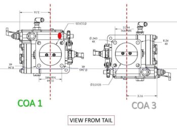
I ended up with 3 different possible install configurations, with the current way as COA 3.  COA 1 is to simply flip the fuel injection servo upside down as compared to how it’s currently installed.  Most of the mass of the servo is low and to the right (thus the current location of the cowling interference), which I would then of course transfer to higher and more to the left.  This would most likely result in having to actually put a spacer in the middle of the two elbows to allow clearance for the top -4 fuel line port.

COA 2 is to mount the fuel injection servo directly to the cold air intake plenum, facing aft.  The drawback to this configuration is possibly having 180º air —most likely more turbulent than if coming in straight— entering the servo intake.  I’ll need to call Allen at Precision Airmotive again and confirm whether or not that is an issue.

Today I flushed out all I could on the present configuration, COA 3, and then assessed COA 2 as well, since COA 1 requires physically moving fuel ports (read: snipping safety wire) on the servo.

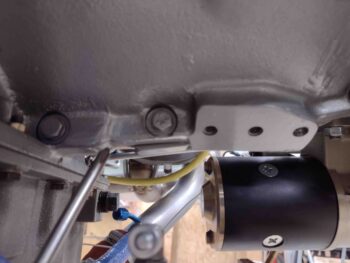
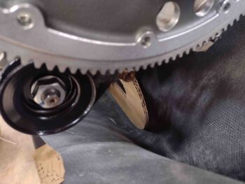
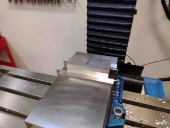
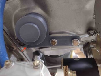
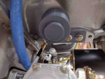
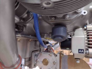
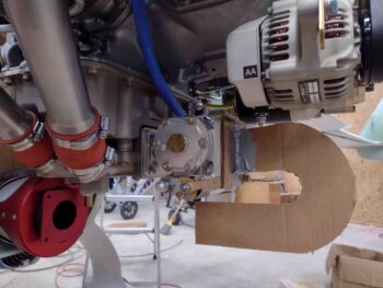
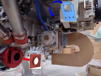
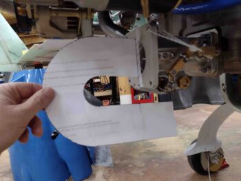
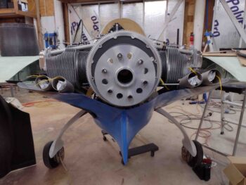
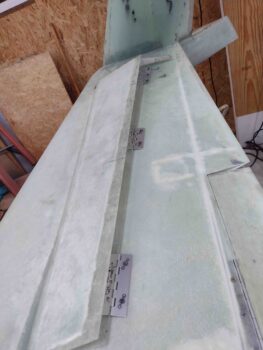
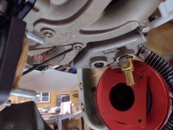
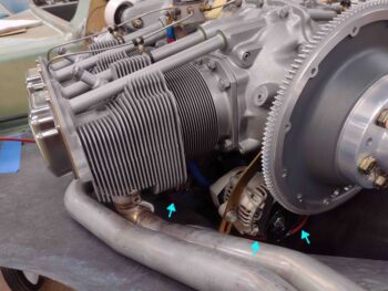
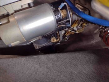
I determined that I wasn’t truly accounting for all my data points regarding the installation of the fuel injection servo unless I at least temporarily mount my Sniffle Valve… the install location on the bottom of the cold air induction plenum which I’m pointing out in this pic:

What is a Sniffle Valve?  Well, for those with a cold air plenum it is a safety valve to ensure that any type of liquid, be it fuel that drains back down from the intake manifolds or perhaps water entering into the system after a good rain is drained free and clear from the cold air intake plenum prior to engine start.  Specifically, it’s to ensure no fuel is pooled up in any quantity that when ingested at engine start would induce a backfire.  No muy bien!

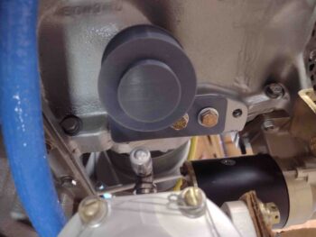
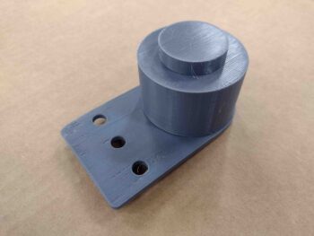
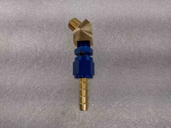
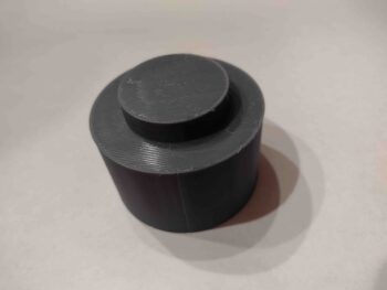
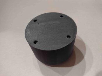
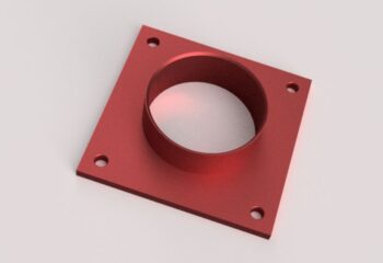
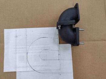
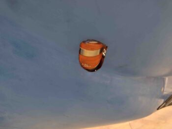
You can of course make a Sniffle Valve yourself, but it is just easier in my opinion to buy one from the good folks over at Airflow Performance.  Here’s what it looks like from the outside.

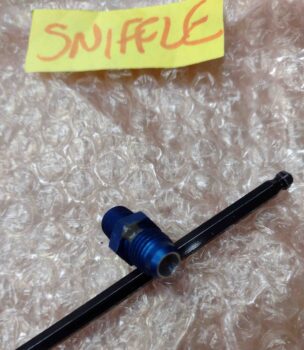
Inside is a ball bearing that falls down/open in its natural state when the engine is off, thus opening the port for all unwanted liquids to exit the plenum during the engine-off state.  Once the engine is started, the vacuum from the air induction system pulls the small ball bearing upwards and keeps it locked in the closed position until the engine is turned off.  Simply but very effective.

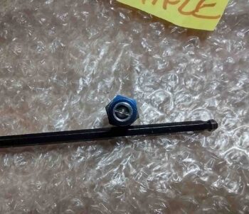
Since our Long-EZs are placed in the grazing positions after engine shutdown and prior to engine start, I am using the forward Sniffle Valve port to drain away any excess/unwanted fluids.  Since this engine is mounted “backwards” I’ll note that on a “normal” install most tricycle gear planes would use the other port, which would be the forward one.  Also in a tractor configuration, the Sniffle Valve port I’m using is what the taildragger bubbas would use.

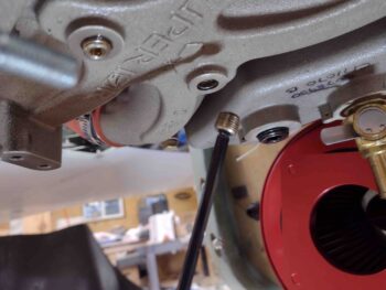
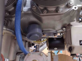
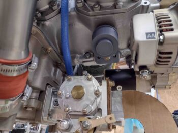
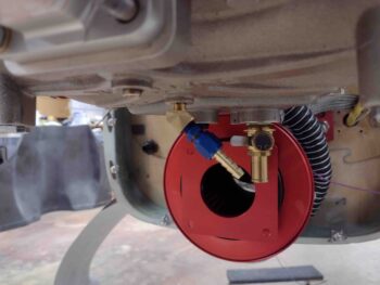
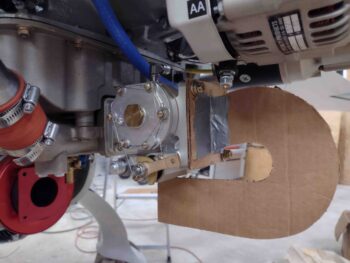
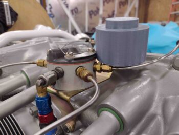
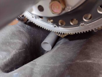
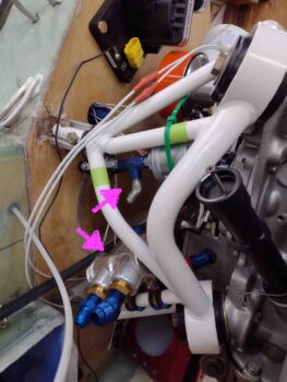
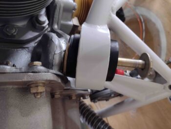
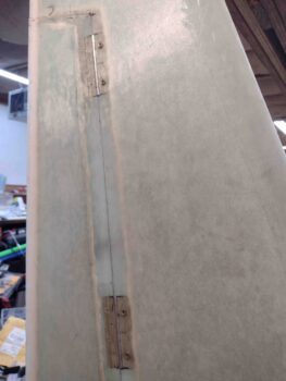
I installed the Sniffle Valve without any thread goop simply as a temp install to ensure clearance with the fuel injection servo, as we have here:

I didn’t grab any shots, but after some trial and error with the current FI servo configuration (COA 3) I determined that by adding washers again to make the bottom elbow 90º (versus actual 85º) and with a 0.090″ spacer in between the two “90º” elbows, I could get some actual clearance between the lower right side of the servo and the bottom of the cowling… maybe 0.08″.  The main fuel hose would still definitely have to be moved from the right side to the left, requiring more circuitous routing.

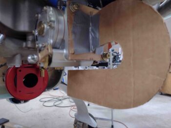
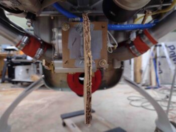
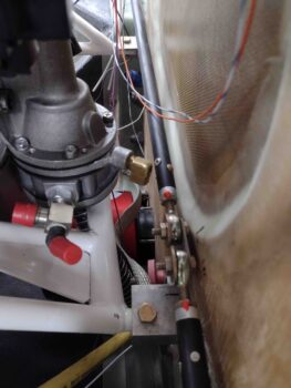
I then grabbed a fairly thick aircraft cable and tested the throttle and mixture cable loop back that would be required for those cables.  I even talked to a custom cable shop in California to inquire about how much I could bend these cables without inducing negative pressure on the cables or effect good operations.

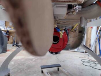
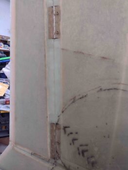
You can just make out the red cable in areas of the lower cowling.

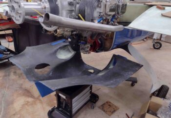
I then took the bottom cowling off to assess fuel injection servo install COA 2.

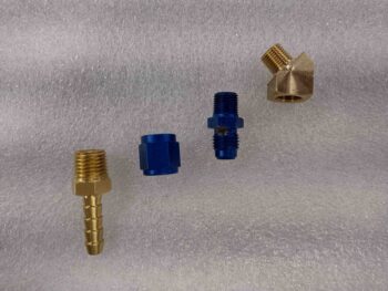
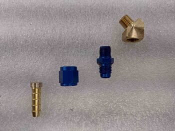
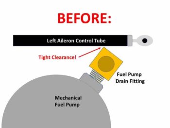
I should note that yesterday I also did an inventory and took a hard look at what options I had for installing an angled fitting into the mechanical fuel pump drain port that would allow acceptable clearance with the left aileron control tube.

I assessed a 90º aluminum barb fitting I had on hand (that I bought specifically for this), but it actually jutted out farther from the fuel pump body than did the brass 90º fitting (with female threads for a straight barb fitting).  The more I looked the more I realized that the brass fitting I had was about as low profile as I was going to get without rolling my own.

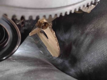
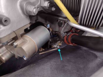
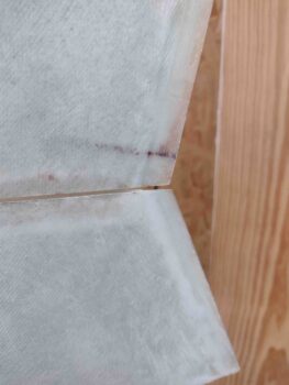
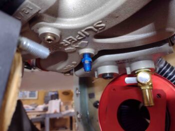
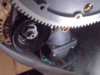
With the bottom cowling off and decent access the firewall area, I wanted to thoroughly flush out this brass 90º fitting to see if it could be used, or if I needed to keep looking for other options.  I had tried the fitting in place, and observed a couple of days ago that there was a scant bit of clearance until I went full right aileron.  Then the left forward corner of the brass fitting just kissed the aileron control tube.  Note that this is with the brass fitting hand tightened into place, so I’m fairly certain I can get one more full revolution of insertion here.

In looking harder at the brass fitting, I realized that it was a cube with the male threads protruding out one side, with the round threaded female port on the bottom to then thread in a barb fitting.  The round channel for the female threads left quite a bit of meat at the corners, which was exactly the area causing the interference issue with the left aileron control tube.

I took the Dremel and knocked down the corner edges a good bit, and after a couple of rounds had an acceptable amount of clearance with the aileron control tube.  Never as much clearance as I would like, but enough that I seriously don’t think under normal flight ops it would cause any interference issues.  Moreover, with now completely rounded edges of the fitting exposed to the control tube, any possible contact during, say, some high G maneuvers would only result in some momentary minor rubbing and possible paint blemishing vs any edges catching against each other.

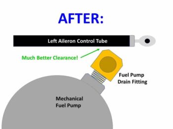
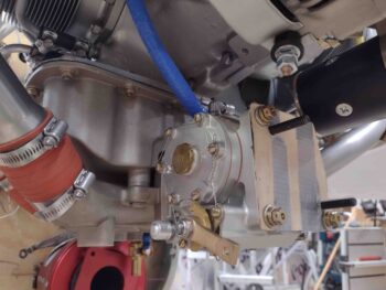
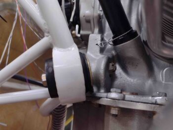
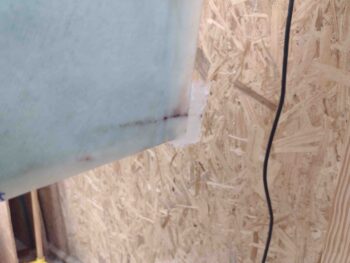
Here we have the mechanical fuel pump drain 90º brass fitting installed (remember! here it is only hand tight) after I rounded the sharp-edged corners.  Clearance is still tighter than I’d want, but this is about as good as it’s going to get unless I can find (or make) a lower profile fitting.  I’ll keep on the lookout, but I’m going to call this acceptably ok until that happens.

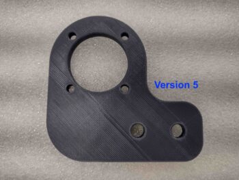
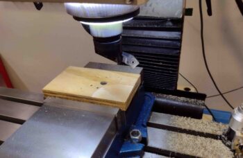
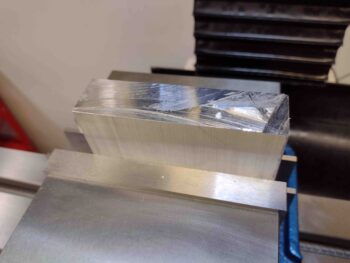
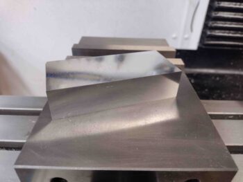
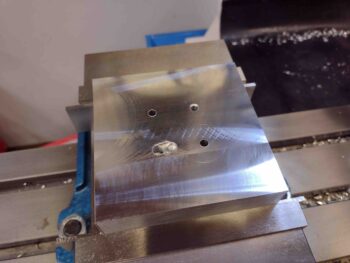
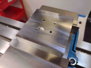
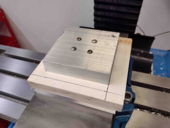
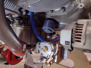
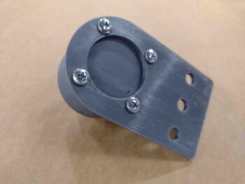
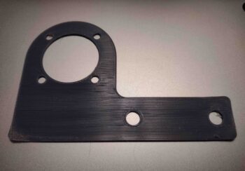
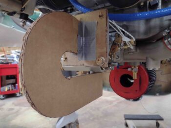
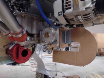
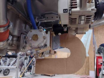
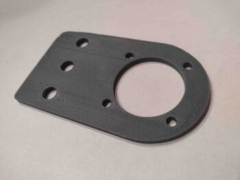
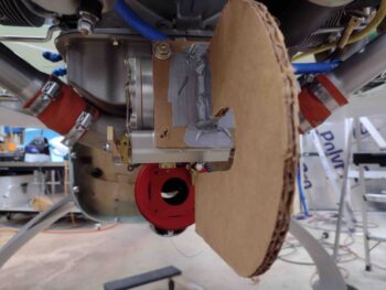
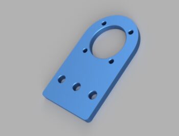
I then ginned up a thin plywood bracket to attach to the (now) aft face of the fuel injection servo as it is mounted facing aft directly onto the cold air intake plenum (COA 2).  I installed 2 CS 5/16″ screws to allow me to then mount the elbows onto the servo.

Which I did here.  Obviously the elbows aren’t installed in a perfectly tight and flush manner as they would be with a proper adapter bracket, but certainly good enough to give me an idea on cowling clearance.

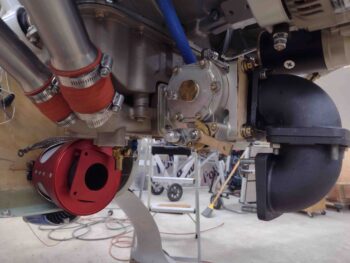
I have to say that the more I looked at COA 2, the more I really like this configuration.  It places both fuel lines in very optimal positions with about as zero interference or clearance issues you can get with this install.  It also places the throttle and mixture levers at good angles and distances from the bracket hard points on the bottom of the cold air plenum.  Moreover, although it requires much tighter length tolerances, it eliminates throttle and mixture cable U-turns in the cowling… with direct Point A to Point B cable runs from throttle quadrant to levers.  Again, so far the biggest drawback is the potential issue with turbulent air entering the servo from the directly attached 180º elbows.  Well, and clearly a slight hit on aft CG as well.

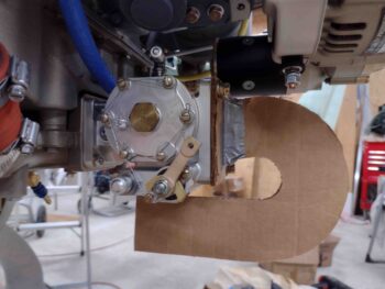
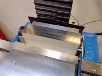
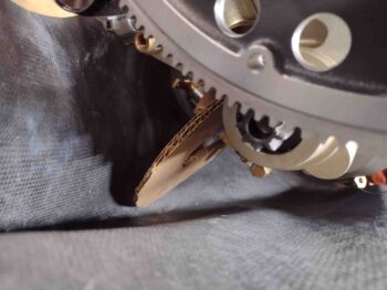
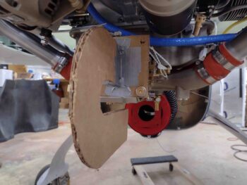
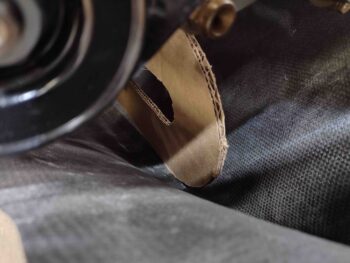
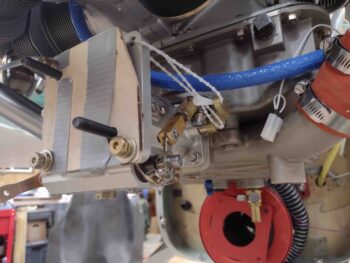
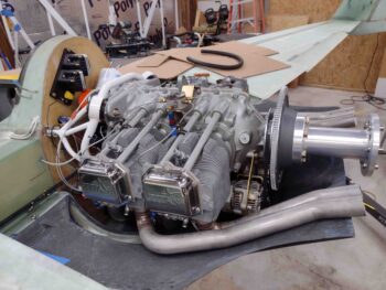
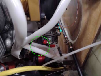
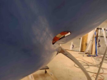
Well, my temporary plywood bracket with attached elbows exposed exactly what I had hoped it wouldn’t: interference between the ~180º elbows and the inside bottom of the cowling…. so much so that with all the CAMLOCs installed on the right side of the cowling, there was no way to get ANY CAMLOCs installed on the left side.

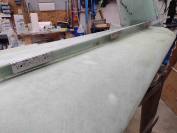
Here’s a shot from the right side of the aft-facing fuel injection servo and the ~180º elbows that are interfering with the bottom cowling fitting.

While not what I had hoped for, the data that I’m collecting from these various COA test installs is helping build a decision matrix for getting this fuel injection servo installed in the most optimized manner for this engine-cowling combo.  If I go with COA 2, it appears that I would pretty much have to fabricate my own air duct to get the air from the RAM air can into the fuel injection servo.  This might ultimately be a blessing in disguise given that I could most likely make it tighter and thus possibly add 2-4″ of a straight air intake just before it enters the fuel injection servo.  Not to mention that it would almost certainly be much, much lighter than these 2 bulky aluminum elbows.

Pressing forward!

Chapter 23 – Engine mounts shimmed

Today I finalized setting up the engine hoist which allowed me to remove the bottom engine mount bolts, lift the engine slightly and slip in an AN970-7 large area flat washer as a shim between the mount/engine flange interface on each side.

Here I’m installing the shim on the lower right engine mount.

And here I’ve shimmed the lower left engine mount using an AN970-7 washer.  Note that this is a test run on the shimming to see how well it works.  There is still a very good chance that I will pull the engine off the mount, work & tweak a number of things before then re-attaching the engine to the mount…. subject to further assessment.

I used my digital level and found that with the lower engine mounts shimmed that the engine was now sitting at 1.5° on the left side and 1.8° on the right side (vs plans 2°).  Remember, I haven’t leveled the fuselage so these are loose numbers and relative to the current longeron angles, and each other.  I know my shop floor is uneven, so I would not be surprised if there is a slight induced twist to the fuselage due to it sitting at an angle in the shop for the wings to fit on.

I then prepped the lower cowling and gathered up everything to put it back on the bird.  I’ll point out that I remounted the fuel injection servo on the 90°+85° elbows.

The lower cowling was a bit difficult to get on, more so than usual, and I found the main culprit being the fuel injection servo (see below).

I will note that there is definitely more noticeable clearances with the right side exhaust pipes… very close to them not having to be reworked if push came to shove.  The left side exhaust pipes (above) though went from pressing hard into the bottom cowling to simply touching the bottom cowling… those still need some serious remedy.

My guess is that I probably gained somewhere around 3/16″ more clearance on the aft end between motor stuff and cowling.

The issue with the cowling being so difficult to get mounted back on is that I tried going with the 90° top and 85° bottom elbows to mount the fuel injection servo.  There is a safety wired port on the bottom of the fuel injection servo that is definitely protruding downward and pressing into the bottom cowling floor keeping it from sitting in its normal, higher position.

Moreover, with the 85° elbow in place the primary fuel line connection port has ZERO clearance with the bottom cowling (light blue arrow)… I can’t even slip a thin popsicle stir stick under the port cap, between it and the cowling.

Clearly, the fuel injection servo configuration will have to be reworked, and I have about 3-4 different options that I’ll entertain on just how to do that.  To be clear, the very LAST option is reworking the bottom of the bottom cowling to allow it to fit.

I also assessed the fuel feed hose exiting the mechanical fuel pump clearance with the frame of the engine mount (dashed green circle).  In 2018 I reported that I would be running this fuel hose on the inboard side of the engine mount frame tube, but I think that was before I added the fire sleeve.

It might be hard to tell in the pic below, but there are two angled engine mount tubes inside the dashed green circle.  The lower one in the background has a steel flange welded in place. At this point I’m certain that I have no choice and I’m going to have to grind off about 1.5″ inches of the aft edge of the flange to allow me to mount an Adel clamp and route the house OVER that lower engine mount tube and then down to the fuel injection servo that route.  There is simply almost no clearance on the inboard side with the fire sleeve installed on the primary fuel feed hose.

I also took a good look at the fuel pump drain fitting (not installed) clearance with the aileron control tubes (light blue arrow)  The engine mount shims of course had pretty much zero impact on the fuel hose routing above, but I would say with the shims in place the clearance here opened up by maybe 0.1″… still very tight, but there IS some clearance and the issue workable.  Again, where is there NOT tight clearances on these birds??

I’m thinking that simple up/down component-to-cowling clearances aren’t as noticeable as angular clearances.  Probably the most notable beneficiary of shimming the lower engine mounts is the right aft cold air induction manifold pipe. It clearly moved slightly aft and up and protrudes very noticeably less than before.

Here is a straight on shot of that.

And you can really see it here, with the cold air induction pipe protruding out way less than before.

My main priorities and concerns with the engine components-to-lower cowling clearances are 1) fuel injection servo – most likely remedied by re-configuring its position
2) exhaust pipes – my preferred remedy would to have them re-welded to fit better, before any possible/required bottom cowling skin rework.
3) Hershey Kiss spinner (specifically flow guide fit) – noting that Mike Melvill had no flow guide [not sure why?], I don’t see this spinner fitting at any point.  I will most likely send it back to Catto or sell it outright.  I think for this type of spinner to work it must have a non-lamp shade style flow guide… one that is more like what Klaus uses/sells (or used to anyway).

Chapter 20 – Winglets/Rudder complete

I started off today by pulling the peel ply off the single BID ply layup on the aft bottom corner of the right rudder.

I then razor trimmed and lightly sanded the edges.  It definitely reinforced the tweaked corner and did exactly what I hoped it would do.

With my K1000-3s finally delivered, I removed the right rudder and installed 2x K1000-3s on the bottom hinge, and one each on the middle and top hinges, for a total of four (4) K1000-3s installed tonight (7 total installed overall).

I then reinstalled the right rudder with all the bolts in place.  I need to do a minor bit of tweaking on the right rudder alignment, as well as some judicious sanding, but overall everything looks really good.

I then repeated the process on the left side rudder.  First I installed the 4x K1000-3s.

And then reinstalled the left rudder, secured with all the required number of bolts.

The left rudder is a lot less of a troublemaker than the right, so I have no notable squawks to report.

Here are closer up shots of the left rudder hinges with all the bolts installed.

Tomorrow will be a bit of a light build day, but I do plan on getting back to work on the engine and cowlings.

Chapter 23 – Engine & Cowling Plan

First off, I’ll let ya’ll know that I’ve had a cold for the last couple of days so I’ve been taking it easy as I assess my engine vs. cowling position issue.

Yes, over the last few days I’ve had a bit of an epiphany on my engine and I thought I would share it with you.

I have to face this issue down, and seriously determine and fix why I’m having any interference or just really tight clearances on my cold air induction pipe, my fuel injection servo, my exhaust pipes. my RAM air can, my mechanical fuel pump drain with my aileron control tubes, and now my prop spinner.

My initial assessment, again, is simple: something just ain’t right in Denmark…. the engine looks like it’s sitting in there fine, but all the indicators tell another story.

Ok, my troubleshooting skills may be slipping I guess.  But I think I’ve got at least two contributing factors.  My bad for not thinking this out better:

Here goes:  Mike Melvill had an O-235 and rigged his engine to be level at 2° nose high per plans… Or about 2° engine high at level longerons.

He then swapped his O-235 out for.an O-360, same mounts pretty much.  Cowling goes on the new engine which is still set at 2° high.

With a planned more powerful motor, I went with 1.4°… but am measuring even less.than that.  Probably not surprising since it’s been on the engine mount for 4 years now.

Now, my bird isn’t on a level floor, nor did I level it, so probably some slight variance.  But I’m measuring 1° on left, 1.2° on right as far as prop up in the back.  That equates to 0.2″ low on left and 0.16″ long on right if I were to bring it back up to 2°.  Significant when you’ve got close to zero clearance on the left exhaust pipes, and a lot of tight clearance issues with a myriad of other stuff.

When I was talking with Marco I wasn’t sure what angle I had set my motor at, but on my blog I noted that I set mine for 1.4º.  I used a .224″ spacer to get to 0.0º on the engine mount, while plans requires a 0.25″ spacer to get to 0º.

Looking at my buddy Dave Berenholtz’s blog, I noted he had a seemingly much tougher time getting the bottom cowl on than I did.  The major difference in our installs is that Dave had an O-320 motor installed on the plane to confirm that the bottom cowl needed to be angled back, or down on the back end.

In addition, Dave’s front top corners are about where mine are, which means the bottom of his cowl where it meets the bottom of the fuselage/firewall is most likely trimmed a good bit more than mine, angling his bottom cowl down on the aft end.  I would think that mounting the bottom cowl as he did caused issues on getting the sides lined up because the back end was actually where it needed to be.

I didn’t have the issues along the sides because I didn’t have my motor installed (huge error) and all seemed peachy keen installing it upside down.  Since, as I pointed out in my video, I only trimmed a max of 3/16″ off each side, most of it way less than that since it was a slight angle, I grossly underestimated how jacked up the cowling was in its design as far as NOT being anywhere close to plug ‘n play.

So…
1.  With my engine angled slightly down in the back more so than stock plans,
2.  Not confirming engine to bottom cowl fit with the engine in while installing lower cowling
3.  Resulting in engine sitting slightly low (some of that may be from 4 years on mounts) and cowling significantly higher compared to stock

I need to take some significant steps to mitigate my engine configuration issue.

#1 – I’ve been researching shims on engine mounts.  Apparently not that uncommon.  A number of reports of engines that start to sag or droop, and shims are used to get them back up to previous level.  I spoke with the Lord mounts folks and, with caveats and warnings to replace old mounts, I’m leaning seriously towards not replacing my mounts and shimming the bottom mounts to bring the engine back up to 2º.
#2 – After I shim the motor up, I’ll then assess its position.  I then need to be prepared for some possible major rework on the lower cowl to re-skin the aft area to open it up for exhaust pipes and spinner/flow guide.
#3 – I will work what I can on the exhaust pipes to possibly have them angled up just a scooch to add even more clearance.

I expect all this to add about a month to the build completion date.

Yep, mods can bite hard sometimes eh?