
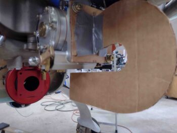
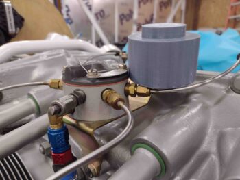
I started off today by re-mounting the trimmed cardboard air induction tube mockup in place on the aft cardboard plate already in place on the aft face of the fuel injection servo. Note that pic #2 shows the targeted mounting flat for the probable move of the fuel injection flow divider to the underside of the engine.
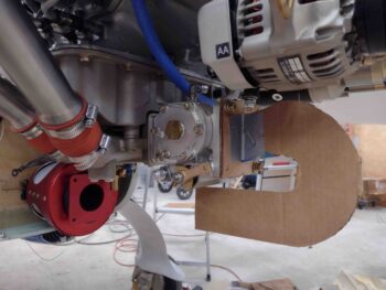
I then put the bottom cowling back on to check the clearance between my cardboard air induction tube mockup and the inside bottom of the cowling.
The good news is that there is actual clearance, the not so great news is that the clearance I got with cardboard tube mockup version #2 was just a hair over 1/8″.
Yep, a game of compromises . . . .
I completely redrew and made up another cardboard mockup for the cold air induction tube for my 180º turnaround into the fuel injection servo. I cut another 3/16″ off the tube at the entrance into the FI servo, pushing the entire tube forward 3/16″. Trimming here helps since the bottom of the cowling slopes downward as it goes forward.
In addition, I reduced the radius of the curve by 0.08″ to 1.92″ vs. my original 2″ radius, which I copied from the Airflow Performance elbows bolted together. Again, compromises.
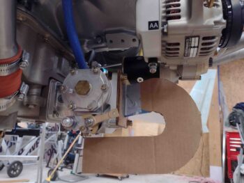
I then reattached my new Version 3 air induction tube to the aft face of the FI servo.
You can see that the clearance between the bottom of the servo and the forward tube of this duct has been greatly reduced, albeit still acceptable. You may be able to see that now the forward pointing part of this tube is significantly higher than the top edge of the RAM air can opening if you drew a straight line from the aft tube. More on this below.
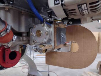
I then re-mounted the bottom cowling and checked the clearance. The cardboard I’m using is 0.269″ thick, so round up for an easier 0.27″. Clearly over double from what I got from the Version 2 mockup, but still a bit too close for comfort… at least for me.

My plan is to trim another 1/4″ off the tube at the attach point/aft face of the fuel injection servo to move the entire tube/duct forward 1/4″ as well. This should get me hopefully another 0.03″ to 0.05″ in clearance. Maybe just a scant more with the bottom slope of the cowling in its diverging from the bottom edge of the tube. Understandably not much, but it still gives me just over 1.5″ of straight air going into the servo air intake entrance —albeit at an angle— and at the risk of repeating myself: I’ll take what I can get!
Clearly the next version of the mockup will be #4. Hopefully this gets me acceptable clearance results that I can live with, focusing of course on the lower aft curve area. To then smooth out the transition between the RAM air can and this air induction tube, I will most likely make up a Version 5 that has the front forward point part of the tube angled down a bit to be as much in line with the RAM air can opening as possible, while maintaining a good clearance with the bottom cowling.
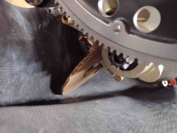
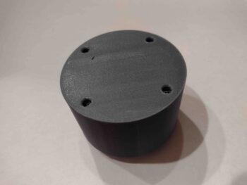
As I was involved with my fun-with-cardboard arts and crafts shenanigans above, my 3D printer was busy creating a basic mockup that I had modeled up in Fusion 360 of my fuel injection flow divider. I put the spec’d threaded mounting screw holes in it so I can attach it to the mounting bracket that I’m also creating.
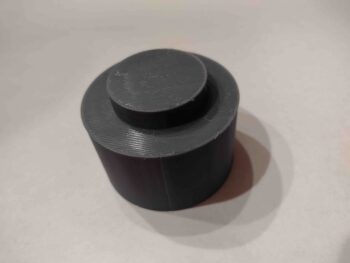
Here is the real fuel distro “spider” next to my 3D printed version, which looks a bit bigger since it’s one solid color, but they are the same size. I didn’t take any extra time to create the intricate features on the top, I just threw a cylindrical cap on top to represent the overall height of the flow divider.
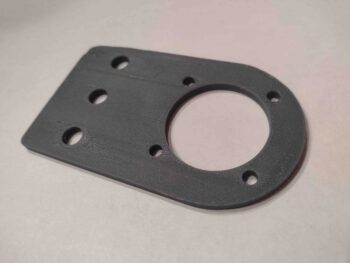
As soon as the fuel distro spider came off the 3D printer, I kicked off the 3D print of my fuel flow divider engine mounting bracket and let it run. Here’s the result.
I called it a bit of an early night and enjoyed a nice dinner Jess cooked up for us. I’ll get back on the build tomorrow. I will note that I’ll be out of town next week for almost the entire week on vacation, then back to it again after that. January will be a very busy month for this build!