
I had to run some errands this morning so I grabbed some hardware for the fuel injection flow divider and mounting bracket.
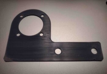
After I returned home, I then mounted the fuel flow divider to the mounting bracket with 10-24 screws.
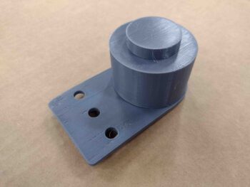
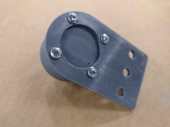
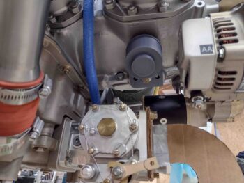
With the bottom cowling off, I then went to test mount/fit the 3D-printed fuel flow divider and bracket assembly. Immediately I realized that in my rush job to model the mounting bracket up in CAD that I had messed up the dimensions for the actual attach portion of the bracket, which should have been a bit wider than the round portion up higher where the actual flow divider attaches. With the bracket’s bolt holes misaligned, I went ahead and mounted it using the center hole.
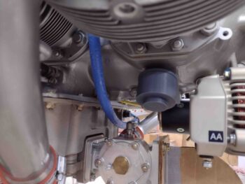
The setup was definitely good enough though to allow me to assess the possible mounting of the fuel injection flow divider on the underside of the engine. I decided that I would want the flow divider as close to the original fuselage station as it is mounted up top. Clearly as far forward would be better for mitigating any negative aft CG impact. Plus, the more equidistant and centrally located the flow divider should translate into shorter lengths of fuel injection lines required.
Jumping ahead a few hours, I spent about 10 minutes revising my fuel injection flow divider mounting bracket to offset the flow divider forward while still using the same engine mounting pad. I figured two hefty 5/16″ bolts should hold it fine, so I eliminated the center bolt hole, facilitating easier install, less cost and less weight. Tomorrow I’ll check out this new design.
I then got onto trimming and testing out Version 4 of my air induction 180º intake tube. After looking at it for a good little bit, I decided to trim the front tube at the intersection with the fuel injection aft face at a slight angle, to get the in-rushing air to enter in a bit straighter. I cut a line with 5/32″ off the top and 1/4″ off the bottom.
I then remounted the Version 4 intake tube onto the aft face of the FI servo.
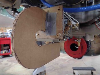
And once again remounted the bottom cowling. As I suspected, I really didn’t get much from my trim. I noted with the angle that the tube attaches to the aft face of the servo, I have 2 opposing actions going on when I trim the front of the tube to push the entire assembly forward: A) Trimming/moving the tube forward pushes further forward in the “chute” that is the bottom of the cowling, that drops down as it goes forward. That’s a good thing, but the drop is a bit shallow.
However, action B) is that with the angle of the top part of intake tube curving somewhat sharply upwards as it goes aft, when I trim the front of it to push the entire assembly forward, I’m also dropping it down a hair as well.
So the question is, which action is making the most difference and winning out?
Using my 0.27″ cardboard spacer, I could see it was definitely easier to slide in and out under the cardboard bottom edge, but that really only gives me more clearance of maybe 0.01″ to max maybe 0.02″ more.
The good news is that my air is entering the servo a bit straighter, but at slightly less total straight distance, and I didn’t really gain much as far as clearance. I’ll have to ponder on this a lot more to see if any panaceas jump out at me.
Meanwhile, I received my respective ACS and McMaster-Carr orders today, which allowed me to assembly the components for my Sniffle Valve assembly. Years ago, when my engine builder warned me about installing a Sniffle Valve, I did some research to get as much info as I could. I ran across Matt’s RV-7 build blog and noted how he angled his Sniffle Valve to get around an exhaust pipe.
Well, I may need to angle mine to get around the 2.5″ SCEET duct that will connect the RAM air can to the fuel injection servo. Regardless if I angle it or not, I will need to attach a drain tube to it to exit out the bottom of the cowling.
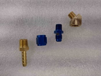
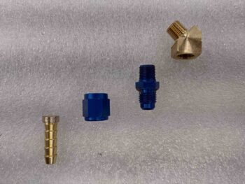
I started by gathering up all my newly acquired components that will make up the Sniffle Valve assembly (left pic). And then used my Dremel Tool to remove and shape a good bit of the material on the threaded barb fitting to allow it to fit inside the AN -4D fitting nut (right pic).
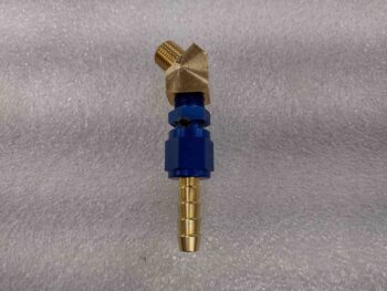
Here are all the Sniffle Valve component parts assembled.
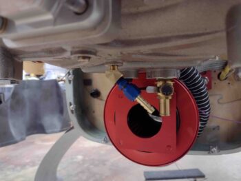
I then test mounted the Sniffle Valve assembly into its port on the bottom of the cold air plenum. Again, if there is enough clearance between the Sniffle Valve and the SCEET tubing, I may not need the 45º street elbow, but better to have it on hand just in case.
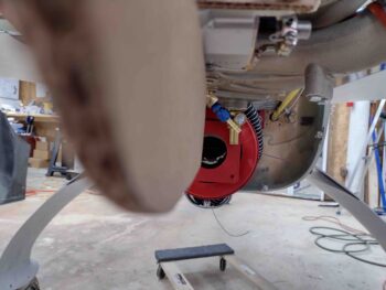
This shot might give a better perspective of how the Sniffle Valve can be angled to avoid the SCEET induction air tube.
I’ll further note that I also just received a barbed brass “Y” fitting that will tie the Sniffle valve runoff tube to the mechanical fuel pump overflow drain tube to then allow me to have only a single tube exiting out the bottom of the lower cowling/firewall flange.
I’ll continue working the air induction system and engine components install tomorrow.