
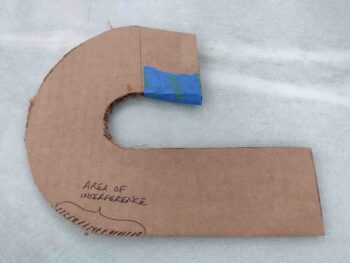
I started off today by transferring my paper 180º air induction tube and bracket drawing to a more 3D version of it in cardboard. The bracket portion is very close to what the flat bracket portion will be that attaches to the aft face of the FI servo, while the flat cardboard mockup of the tube is of course to check vertical clearance… although I did also check width as well (down below).
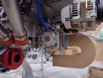
I tried as best possible in these shots to capture the almost perfect alignment between the cardboard “tube” and the RAM air can inlet… although clearly with this distance a perfect alignment is not an absolute necessity.
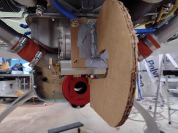
One more shot from the aft side… my camera lens is offset, as this was meant to show everything in excellent alignment on the centerline.
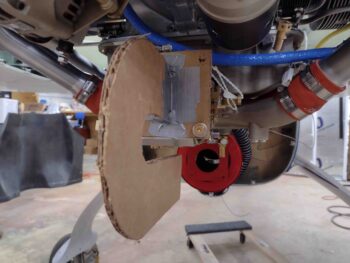
I then mounted the bottom cowling… which thankfully I was able to get completely installed. You can see a very slight deformation of the bottom of the cardboard tube mockup, about 1/16″ I’d guess. Since this is at the aft end of the engine and cowling, I’d like a bare bones minimum of 3/8″ clearance, while 1/2″ would be even better.
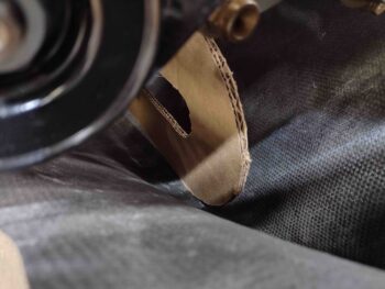
It may be hard to see, but before removing the cardboard tube mockup, I made a Sharpie mark at the aft end to denote where the tube turned upwards on the aft side.
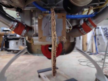
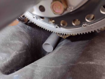
I then took a 2.5″ diameter tube I have on hand and placed it inside the bottom of the cowling with the edge resting on that Sharpie mark: to ensure I had clearance in all directions, but specifically left and right, for a 2.5″ diameter air duct tube. As you can see, I do.
The mockup showed that some configuration tweaks were going to be needed, which means compromise on my requirements. Reluctantly I trimmed a 1/2″ off the straight length portion of tube where it will attach to the aft face of the FI servo. This now gives me only 2″ of straight air going into the servo vs 2.5″ … again, I have to take what I can get.
In addition, I also angled the tube at the entrance just a bit more to raise the entire duct up a bit. This will be the last angle increase I do, and I probably should have stopped at just the 1/2″ trim in length. But I’ll put this back on (tomorrow) and see how the clearance looks.
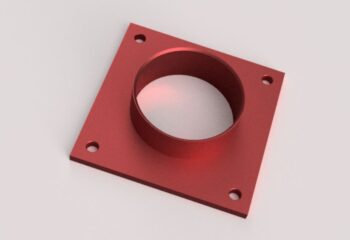
I then confirmed some dimensions on the aft face of my RAM air can where I’ll need an adapter to attach the 2.5″ SCEET tubing coming from the FI servo air duct tube above. I modeled up the adapter in Fusion 360 CAD and grabbed a screen shot. Now, I will point out that the final version will have chamfered corners, but that will be a subsequent milling operation so this is the first phase version of the SCEET tube mounting adapter.
Switching gears slightly . . .
I got a comment from Dave Adams, a very knowledgeable Canardian, on my last YouTube video build update where he advised me to consider mounting the fuel injection flow divider on the bottom (cold) side of the engine to ensure the fuel stays cool in the lines. I get it.
But I had a some in-depth talks with Buly and my engine builder, who both had their spiders mounted up top, and neither had an issue with it up there over countless hours of operation. So now I really do want to know first hand what the difference is between running the fuel spider up top vs down below, but as I thought about remounting the fuel spider down below later on after the bird is flying, I pondered on what this would entail baffling-wise.
I don’t think the mechanics of moving the flow divider down below is all that crazy difficult, just time consuming (read: tedious) and a little pricey if different length stainless steel fuel injection lines are required. However, again, the real issue I’m starting to see is maybe having to redo some baffling. I’ll assess further.
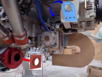
Regardless, I went ahead and scoped out a good bit of the details of moving the fuel flow divider/spider down below. I honestly don’t remember, and couldn’t find after a few minutes of Internet searches, what the 3-holed angled pad is on the aft underside of our engines (front side for tractor drivers), but that’s where I decided to mount the inverted fuel flow divider (ok to mount in this configuration per manual). And yes, my initial swag conveyed that at least 2 new fuel injection lines would need to be bought for relocating the spider down under, as well as some new hardware.
I mic’d up the dimensions of the this possible fuel spider new mounting pad as well as the fuel distro spider body and ginned up a mount in Fusion 360 CAD.
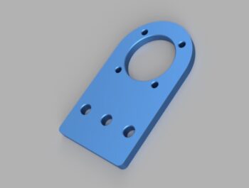
To be clear on where these CAD’d and machined adapters/brackets/mounts will go, I plopped them into the first pic from above.
Tomorrow will be round 2 of mocking up the 180º air induction tube to ensure that I’ve got the minimum clearance required. Then I’ll start working on the best way to construct it to ensure a nice clean internal surface on the air duct tube.