
Merry Christmas and Happy Holidays everyone!
Over the last few days, besides getting ready for Christmas and truly enjoying this holiday (for what it really is!), I’ve been doing a lot of research on primarily my fuel injection system, but also a multitude of other engine components, including fuel system stuff too. I’ve dropped a number of orders for fittings, more stainless steel hose, hardware, and aluminum and stainless steel for machining induction tube adapters, cable brackets, etc.
Today I finalized my Course Of Action (COA) assessment. I found a critical error I made with labeling one of the Precision Airmotive diagrams in getting my throttle lever push-pull direction backwards. Once caught and corrected, that pretty much nixed COA 3 —fuel injection servo facing forward as I had planned from very early on.
COA 1 has the FI servo facing forward as well, just inverted 180° from COA 3. Since this puts most of the offset “mass” of the servo to the left and up high (clearly opposite of COA 3), it would require a spacer in between the two ~”90º” elbows to allow clearance for the topside -4 fitting (still no room for it on the bottom) and Sniffle Valve.
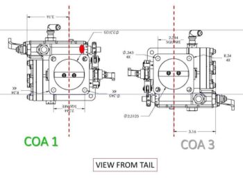
Using a spacer for COA 1 puts me right back as having a lot of the same issues as I was fighting with COA 3. Worse, it really jacks up what little clearance I had —due to the contour of the bottom surface of the cold air plenum— for the top -4 fitting. Moreover, the alignment between the fuel injection servo intake and the RAM air can exiting air is awful… off elevation-wise by over 2″ in a distance of about 5″ from face to face.
The bottom line is that both forward facing COA 1 and COA 3 are no-go’s. That leaves me with only the aft-facing COA 2 as the last viable option. Clearly I need to make this option work.
First up, my plan to buy my way out of work failed. Unless I resort to some major surgery on the Air Performance air induction elbows, specifically the bottom one, then I’m once again left with no clearance with the bottom inside of the cowling.
To facilitate adding components and adapters, obviously the elbow mating flanges are square with threaded studs to attach to servos, filters, plenums, etc. The squareness of the flange required for threaded studs and the area required to place a gasket for a nice airtight seal adds to a lot of the volume of these elbows. Plus, let’s be honest in that they are a bit hefty at over 1.5 lbs. total… more than that once all the hardware is added.
By simply changing the shape of the bottom elbow to a comparatively thin-walled round tube, it would eliminate a lot of the lower clutter that cause the clearance issues with the inside bottom cowling. Thus, using the same curve radius: 2″, I drew up a possible replacement for the combined elbow assembly.
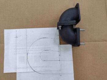
I’ll note first that I wanted as much of a straight shot as possible entering the fuel injection servo to calm the air down and have it less turbulent as it enters the servo. My limiting factor is going aft, where I will hit the wall —literally— since at 6.6″ aft of the servo face will be the aft lower baffle wall to seal off the hot vs cold side of the engine cooling air.
With a constant 2.5″ diameter duct and maintaining a 2″ minimum diameter curve, this gives me just a hair over 2.5″ of “straight” air prior to entering the servo… with one caveat: to get the entire ductwork up higher and off/away from the bottom cowling “floor,” I canted the straight segment up around 5º from the start.
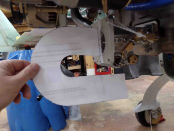
I have to say that initially, this configuration looks fairly promising. I dropped the bottom tubing going forward down from the servo plate 1″ to allow for clearance with the bottom port cover plug, but I do have wiggle room to scooch the entire duct up a bit if required. Tomorrow I’ll make up a quasi-3D model of this duct, test it out on the servo and then check the clearance by mounting the bottom cowling.
Almost certainly more tweaks to follow …
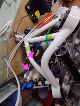
In other news: off and on all day I’ve been playing around with locations to mount the external oil Verrnatherm (more research on that required) and the engine sensors. With so little space for these components, it’s really driving me to minimize the use of “traditional” manifold blocks and simply go with 1/8″ NPT 3-way T-fittings, as here with the oil pressure sensors that were in a manifold that I’m chucking out in lieu of employing a more diminutive T-fitting.
I also assessed installation locations and configurations for the manifold pressure sensors block and the fuel pressure sensor. This exercise resulted in a slew of Adel clamps, fittings and hardware being added to the “to-buy” list.
The long slog continues!