Chapter 24 – More Hell Hole fill

Today was a short work day since I had some personal stuff I needed to take care of.  However, I was still able to get another strip of foam added to the Hell Hole cover/floor.

This strip of foam, about 2.5″ wide, filled in right behind the previous one at the front side of the Hell Hole. I set up my dam/form just as I did before, even with the requisite clamps.

I then whipped up some pour foam and poured it into this next section of Hell Hole cover/floor.

A bit later I pulled the form off.

I shaped the outer surface of the freshly inlaid pour foam section to match the surrounding level of the existing foam, and then prepped the interior surface for glass.

I laid up a ply of BID overlapping about an inch on all sides, again on the inside surface.  I then peel plied the layup.

I’m thinking that tomorrow I should be able to finish the repetitive task of pour foam and glass and move on to constructing the RAM air scoop.

Chapter 24 – Filling Hell Hole

Today was all about refining the aft bottom fuselage and Hell Hole cover plan, and then filling in the parts of the remaining opening between the two Hell Hole side fills that covered the bottom surfaces of the main gear.

The goal here is to fill in a good majority of the Hell Hole cover, or floor, in small sections that can be somewhat easily and manageably glassed.  The first strip was along the aft edge of the lower fuselage where the Hole Hell arguably officially starts.

I made up a duct-taped-covered cardboard dam/form/mold and secured it in place.  The clamps on each side are pressing against wood strips that keep each end of the flat mold piece pressed tightly against the existing Hell Hole floor.

I then whipped up a batch of pour foam and poured it into the form.

Here’s another shot of the quick-curing pour foam.

I had assistance today from my beautiful helper, Jessica —in her shop debut— as she very adeptly cut, cheese-grated and leveled the freshly inlaid pour foam to match the existing sides.

Here’s the final result from Jess’s handiwork… very nice.

I then walked Jess through her first fiberglass layup as we got the front edge of the inside Hell Hole to aft fuselage edge glassed.

Jess then helped me make up the form on the aft side of the Hell Hole opening, on the front side of the firewall, with a strip about 2.5″ wide.  She whipped up her first batch of pour foam and did an excellent job filling in yet another section of the Hell Hole cover/ floor.

Although I didn’t get any pics, a bit later I then removed the excess foam off this last pour and shaped/leveled it to match the foam on each side.  I then glassed the inside surface with a ply of BID overlapping onto each side and of course also onto the firewall.  All the layups were peel plied on the Hell Hole floor surface (foam) as much as possible.

Tomorrow I’ll press forward with filling strips of the remaining Hell Hole opening in and then glassing them on the inside.


Chapter 24 – Hell hole corners

I started out today trimming the inside right Hell Hole wall/corner/floor layup and pulling the peel ply.  It’s not the prettiest layup on this bird, but everywhere I looked it came out nice and solid.

Here’s the aft side where the interior right Hell Hole wall intersects with the front face of the firewall.

Before I proceeded any further on enclosing the Hell Hole with foam and glass, I figured I needed to run the Nick Ugolini Princeton Long-EZ fuel tank probe wires from the Hell Hole up (again, down in this configuration) into the CS spar.  Even with the bird inverted and most of the Hell Hole open it took me about 45 minutes to run the right side wire, whereas it only took 3 minutes to run the left.

I then built the form over on the left side of the fuselage to fill in below (above as situated here) the gear leg and create the left side lower “corner” wall for the Hell Hole.

Here’s another shot of the left side form, from the outside.

I then filled it up with pour foam.

And removed the forms a bit later.


Here’s the lower left side Hell Hole “corner” foam in its initial state.

I then cut, sanded and filed both the inside and outside of this freshly poured foam.

And then laid up a ply of BID, in 5 pieces… so there were a number of overlaps.

Here’s a final shot of the lower Hell Hole “corner” glassed on the interior.  Note that I peel plied from the inboard edge outward with a 2″ wide strip.

I then left the layup to cure overnight.

Chapter 24 – Lower fuselage/hell hole

I started this morning by filling in the very aft area of the lower fuselage with pour foam, obviously inside the dams/forms I created last night.

A little while later I pulled off the forms.

Here are a couple side shots of the applied pour foam up to this point.

And a look at it from the aft firewall.

I then used a hacksaw blade and my “cheese grater” to knock down big pile of cured pour foam.

I then set up a form to fill in the area under (“over” when inverted) the right gear leg.  In addition, in this inverted state I set up a “floor” to in turn create a section of the bottom floor of the hell hole. Moreover, I set up the thickness so that once the foam cures it’s at the appropriate height to glass almost immediately with only minor tweaking.

Here’s another shot of the form for the right hand “corner” of the exterior hell hole floor/wall.

And a couple external shots of that form configuration as well,

And here is all that with the pour foam in action.

After the pour foam cured, I then removed the forms and knocked down the excess foam.

I then dialed in the surface level of this freshly added foam with my sanding block.

I cleaned up the inside, removed excess foam and sanded the surface to rough it up a bit from the smooth glossy surface it gets from curing against duct tape.  I also ensured all the transitions between foam and existing fuselage structure was even and worthy of glass.

After micro’ing up the foam I then laid up a ply of BID, in 3 pieces, that overlapped onto the lower longeron, firewall and aft fuselage edge. I then peel plied the inboard (nearest the opening) edge with 3″ wide peel ply tape.

This was definitely a challenging layup primarily due to the lack of access I had to the areas where I was laying up the glass.  I used the bigger stir sticks as a squeegee in the corners and to ensure the glass was attached to the foam with as few bubbles and air gaps as possible.

I then left this layup to cure overnight.


Chapter 21/24 – Lower fuselage/hell hole

Today I started out by removing the NACA shaped plug from the NACA scoop I glassed last night with 2 plies of BID.  I also razor trimmed the glass and pulled the peel ply up.

As with many things on this build the scoop isn’t perfect, but I’m thinking it meets the minimum design criteria and will work fine.  Its appearance of course will look much better after some micro finishing.

I then turned my attention to the strake/wing junction layup that I also knocked out last night.  I secured a long straight edge to the marked intersecting line with a clamp and tape.

And then cut the line with the Fein saw.  I was able to remove the tape and foam from the first 10″ or so, which provides a pretty good view of how the entire intersection will look.  I’ll add a ply or two of BID on the inside to reinforce these flanges once I remove the wings.

With the strake/wing intersections glassed and gap minimized to about 1/16″ I then pressed forward with filling in the lower aft fuselage and hell hole.

I’ll state that of course there is no one right way to do this, and I’ve seen a lot of builders simply create dams and pour all the foam virtually at once and then start carving.  I would probably do this normally, but in my current mood I decided to attack it with a bit more precision.  Which of course will take a bit longer.

I started on the right lower sidewall, just above the gear leg, to create the lower fuselage wall.  My goal is to create the wall about an inch thick that will then allow me to roll right into glassing the interior surface of the hell hole.

I also want to get the requisite gaps in place on the top of the gear leg (underside as situated here) taken care of right off the bat, then get the lower gaps (topside here) taken care of in short order following that.

Another shot of the right internal lower fuselage/hell hole wall forms.

I then created an external side form for the lower right fuselage.  Not surprisingly, it took a bit time –trial and error– to make these forms.

I then taped the external lower right fuselage form into place.

Here’s a view from the “top” side . . .

And a shot after I poured the first batch of foam into place on the lower right fuselage.

Here’s a shot a bit later, with the lower left fuselage foam poured in place.

Also you can see where I determined the point of conversion on the lower fuselage with a straight line coming from the firewall bottom edge.  I marked these convergence points — left, right and center– on the lower fuselage (abound mid-point on the Kevlar) and then built a dam just a bit forward of the convergence marks.

Here we have the front area –on the lower aft fuselage– all dammed off and ready for pour foam.

It was quite late at this point, and since pour foam cures fairly fast I decided to call it a night and start fresh tomorrow.

Chapter 21/24 – Wing/Strake Junctions

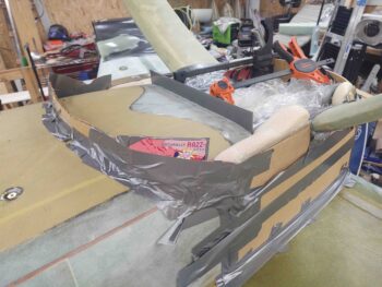
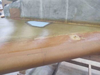
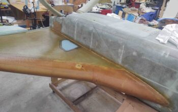
Over the last week or so I’ve asked Marco to take some pics of his flying bird, JT, as he has it down for some upgrades.  The pics I requested were of the strake-to-wing junction since I suspected, and had noticed in passing, that they were not constructed as the build plans would have you do so.

Today I doubled down on my effort to come up with a plan for creating both the wing and strake intersection (gap) lips.  I noted my buddy Dave Berenholtz went with 3 plies of BID across the gap, and then micro filled later.  In retrospect this may have been the easiest route and I mighta oughta shoulda taken it.

I also queried Mike Toomey on how he went about working his strake-to-wing junctions, which was fairly inline with what I found in the old CSA issues as spelled out by Ken Miller.  They both recommended filling the gap with foam first, then glassing.

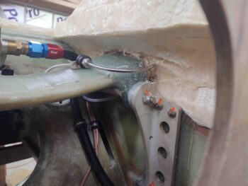
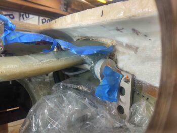
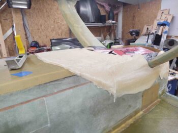
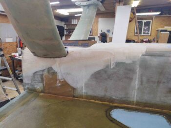
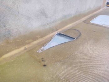
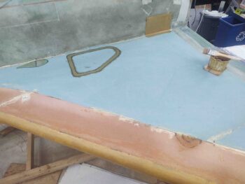
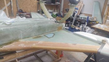
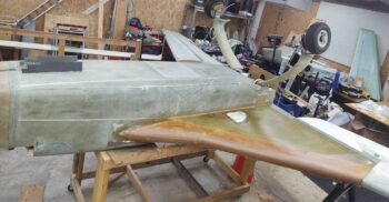
Regardless of any method I used, the front edge of the right wing needed the micro fill that I had put on years ago to be removed before I could layup any glass over it.  So I marked a line about 1.5″ wide…

and then sanded away the micro fill.

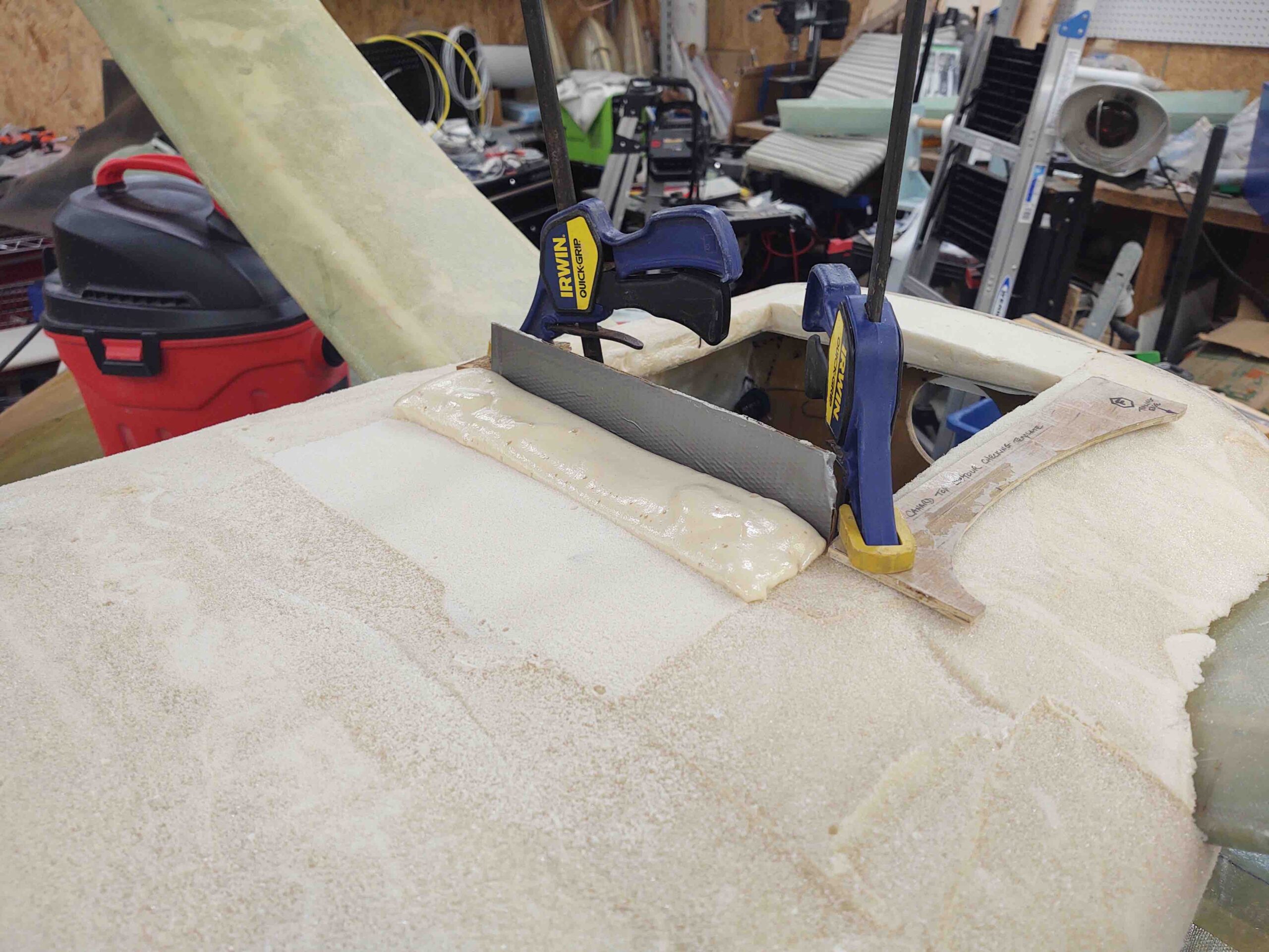
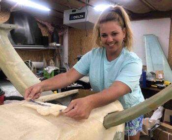
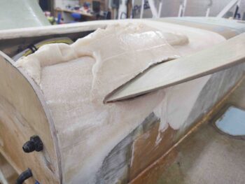
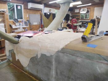
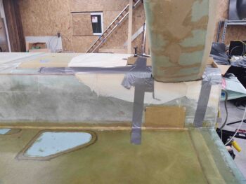
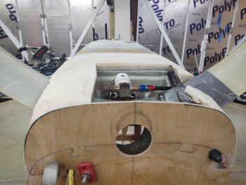
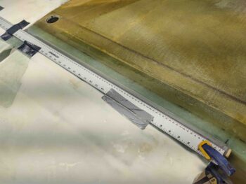
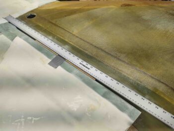
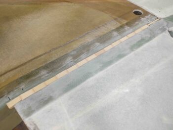
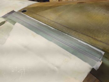
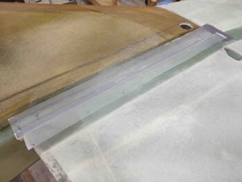
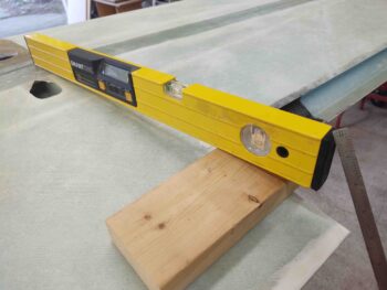
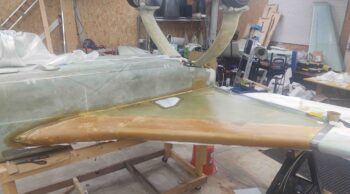
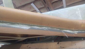
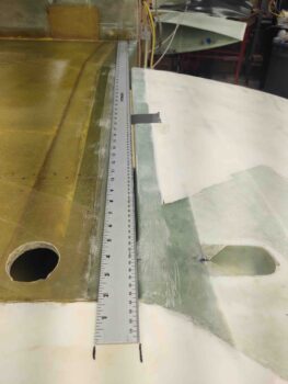
As per Ken Miller’s instructions, I used a long straight rule that allowed me to make alignment marks on each end for what will be the cut line that will mark the respective edges of the glass lips… which themselves will cover this gap.

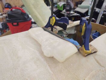
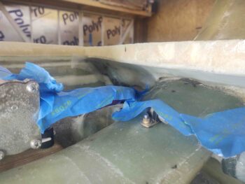
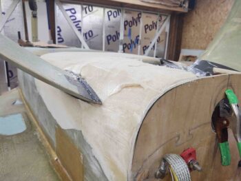
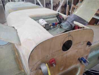
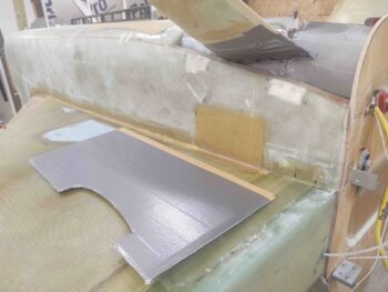
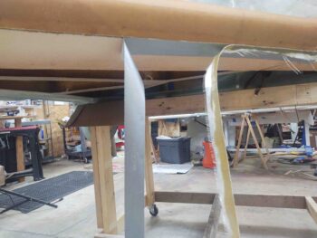
Somewhat like Marco’s bird JT, I wanted the major/wider lip on the aft side of the strake, and the minor/narrower lip on the front of the wings.  I taped a temporary 1/4″ plywood spacer onto the front face of the wing to give me what will be that narrow lip.

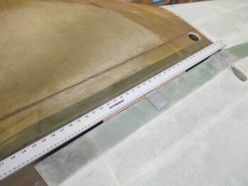
Here’s another shot of the long rule and marks to create a narrow lip on the wing side and wider lip off the strake.

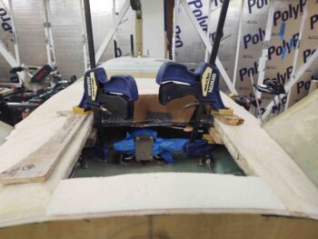
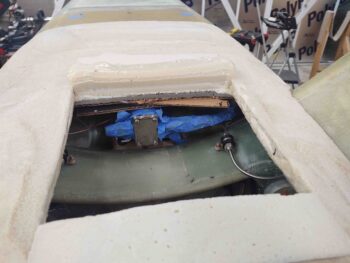
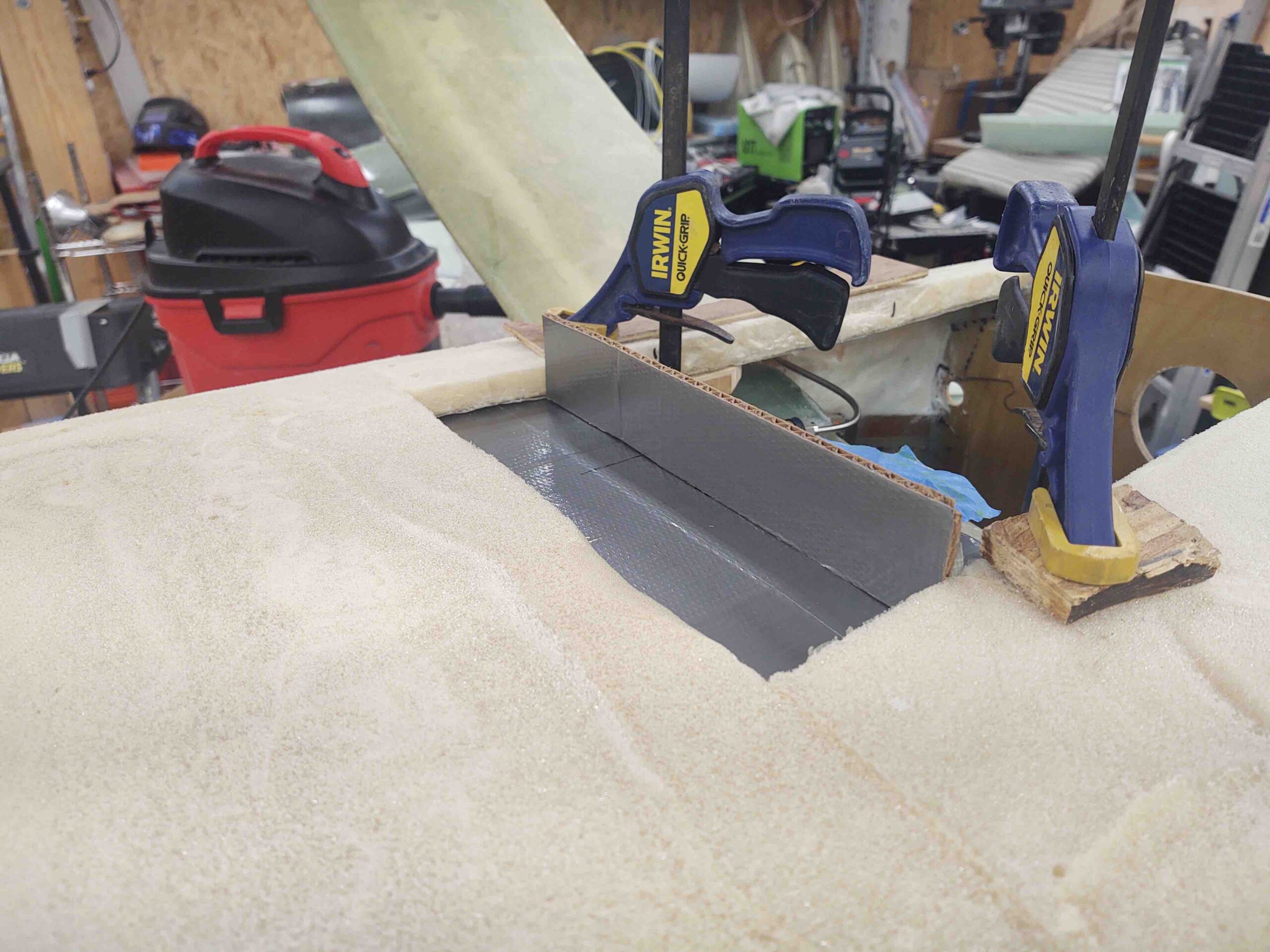
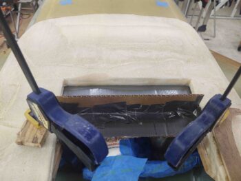
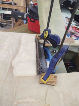
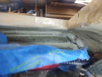
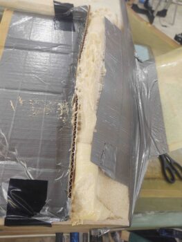
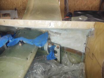
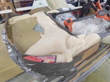
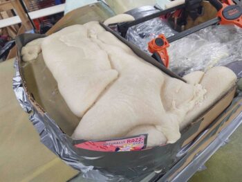
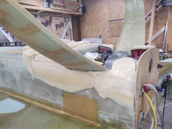
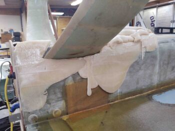
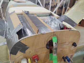
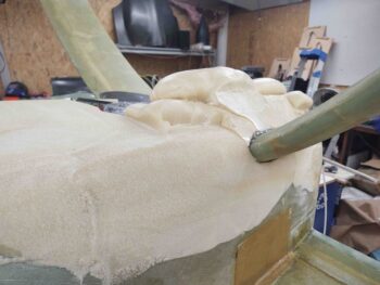
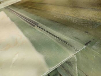
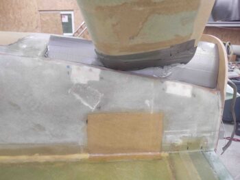
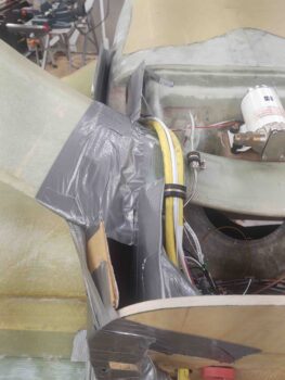
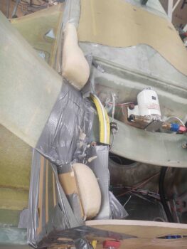
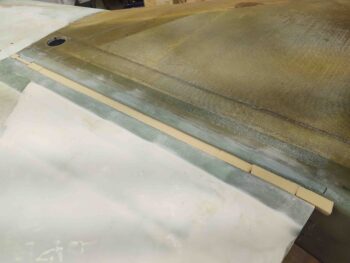
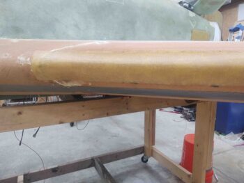
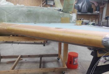
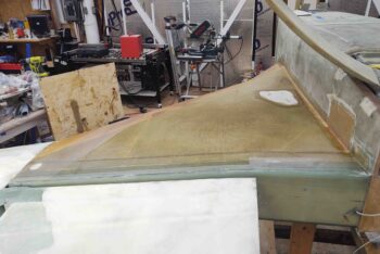
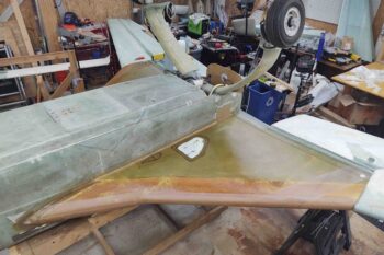
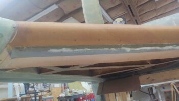
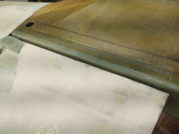
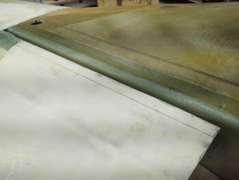
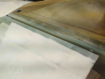
Since I have so much scrap urethane foam hanging around, I went ahead and used that to fill in the strake/wing gap… again, as per Ken Miller (urethane) and Mike Toomey (spray foam).

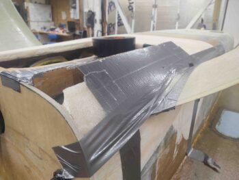
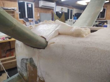
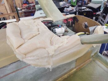
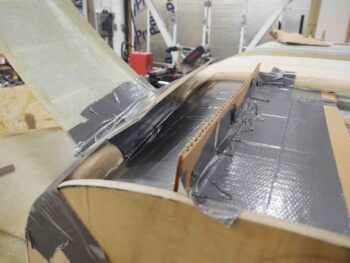
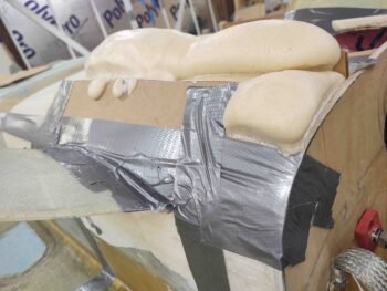
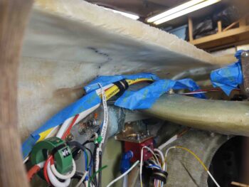
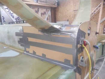
After sanding down the foam and shaping it to be as good of a bridge as possible between the slightly uneven surfaces of strake and wing (a bit more pronounced on the left side), I then taped over the top of the foam with a strip of duct tape to act as a mold release betwixt glass and foam.

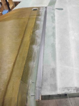
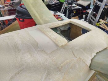
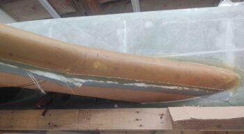
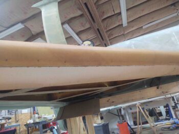
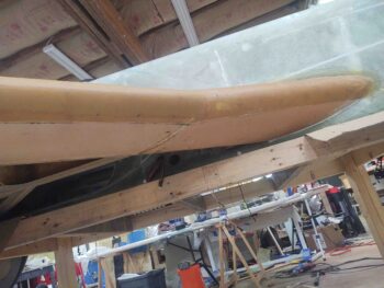
I then laid up 2-ply BID tapes on each side, with the bottom tape being 4″ across the gap, fairly centered, and the top ply being 3″ wide across the gap… again, fairly centered. I then peel plied the layups.

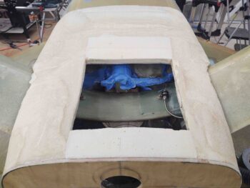
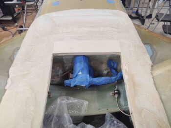
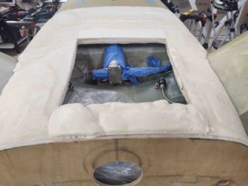
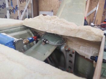
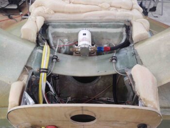
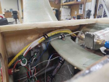
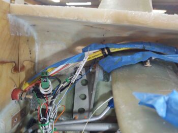
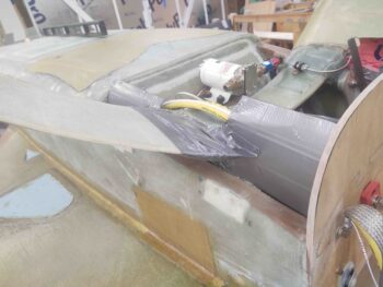
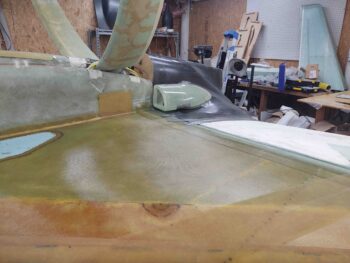
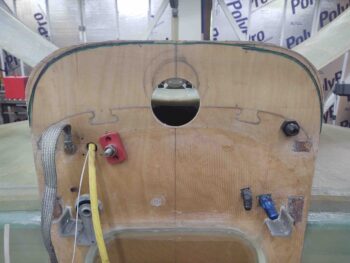
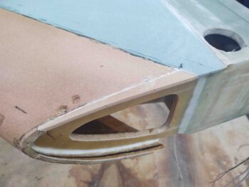
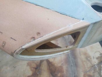
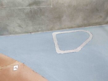
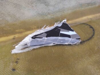
Today I also finalized my research on creating a NACA scoop for the GIB air vent. I have never constructed or designed a NACA scoop, and again I just used the template that was in the plans for the canopy skirt air vent.  I did want to ensure that since this is a bit different construction technique than the canopy skirt vent that my internal scoop design was optimized.

I’ll say again (maybe?), thank goodness for the searchable CSA newsletter thumb drive I bought… great archive of really good info.  With that in my back pocket I tweaked the NACA scoop a bit before prepping it for glass.

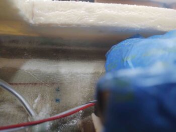
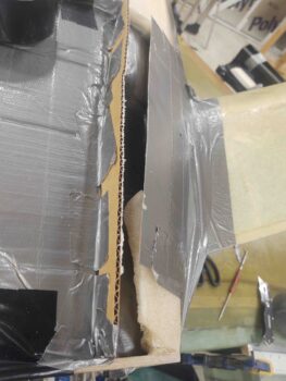
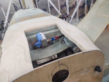
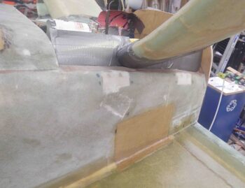
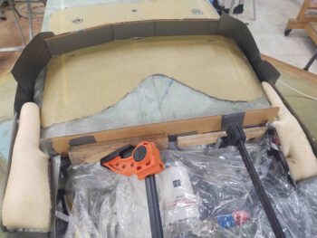
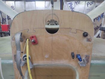
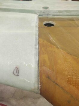
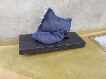
As you can see, I also created a foam plug to help press all the glass outwards against the sidewalls and down onto the “floor” (as situated) of the scoop.

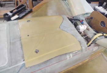
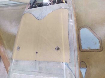
I laid up 2 plies of BID inside the NACA scoop, after creating essentially flox corner walls.  I then peel plied the bottom surface of the scoop and then put the foam plug in before weighing it down with almost 20 lbs of weight.

Tomorrow I’ll clean up these layups as I move on to shaping and glassing the aft bottom fuselage and hell hole cover.

Chapter 14 – Lower firewall trim

One of the main reasons I mocked up the lower engine cowling was to determine the intersecting lines between it and the lower firewall.

I played around with the cowling for quite a bit to get it set the best I could against the firewall.  It may not be perfect and I realize some rework may be required, but I have to have a starting point if I am to fill in the bottom of the hell hole area and create the lower aft fuselage section.

With that, I trimmed the firewall to create an edge for the upcoming lower aft fuselage and hell hole.

Over the next few days I plan on slowly building “up” (technically down of course) the sides of the fuselage which will then culminate in me creating the bottom of the hell hole cover with an integrated RAM air scoop.  That’s the plan at least.

Chapter 21 – Lower right strake cleanup

Before I started the cleanup on the right strake bottom skin layup I wanted to get the ply of Kevlar laid up on the bottom aft fuselage… that will serve to protect the bottom side of the GIB thigh support sump tanks if I were ever to have a hard landing that ripped the main gear off and resulted in a belly slide down the runway/ground.

I made a bit of indentation on the aft side of the Kevlar ply in case I need to dig into the original bottom aft center fuselage for positioning of the RAM air scoop that will be coming soon.  After I laid up the Kevlar I peel plied it.

Also, I should note that before actually laying up the Kevlar, I test fitted the left and right fuel sump drain valves to ensure I had enough clearance around them to insert a socket on them to install them.  The right side channel in the bottom skin needed to be widened just a hair, and after I got it so I could slip a socket in there I proceeded laying up the Kevlar.

After nearly 2 hours of cleaning up the bottom right strake layup and removing all extraneous glass, I then cleaned and mocked up the bottom engine cowling.  I went ahead and temp mounted the armpit air intake scoops as well to get an idea how they will fit.

Here’s the protective Kevlar ply on the aft bottom fuselage after it cured and I pulled the peel ply.  At this point I dug out the foam around each of the thigh support fuel sump drain valve points and filled in the edge of the channels with flox, not only to provide a stronger bottom fuselage skin to internal skin bond, but to clean up the raw foam appearance of these drain valve points.

With the drain valves and the center threaded hardpoint that installed before I skinned the outside the fuselage eons ago… I think the Kevlar looks like Pokémon!

Also note the right strake glassed trimmed away from the GIB strake window and the GIB air vent NACA scoop.

The next few days are going to be busy with some social events, but I will attempt to press forward as much as possible on the aft bottom side of the fuselage and hell hole.

Chapter 21 – Bottom right strake glassed

My first task of the day not only is a critical crosscheck, in my opinion, for dialing in the strake configuration in regards to how it aligns with the wing –specifically at the BL55 jutout– but also a big qualifier regarding if I plan to fly at least with some of my plane (eg strakes) in primer or not.

The task I’m referring to is checking the wing incidence of both wings and comparing to get a good idea how the wings are set to each other. In other words, how are my chances looking of not having to go back and tweak a wing incidence by adding or reducing washers as spacers at the wing bolts?  Well, if Waiter at IflyEZ.com is correct in his method of ascertaining this very thing, then I have to say I’m looking pretty darn good.

If you’ll remember I did this exercise with the wings installed upright and the results were spot on.  With that being the case I guess it’s not surprising that with the wings inverted I got the same excellent result.  With the bubble in level smack dab in the middle, I measured 4.65″ from the top corner of the level to the trailing edge on each side.  The key to this of course is that the level be positioned at 0° by using the wood block… the idea being that if one wing incidence is off from the other, its 0° “level” will result in a different measurement from level top aft corner to trailing edge: clearly either more or less depending which way the incidence is off.

With my incidence confirmed, I did one final check of my right strake outboard edge and leading edge intersection with the right wing.  I did do a bit of final tweaking.

I then started on the right strake bottom skin layup by spending well over an hour laying up the 2 different Kevlar layups: leading edge 4″ strip and rectangular protective patch over tank fuel line feed in the sidewall.  I then laid up the 1 ply of reinforcement BID for the GIB window lip (this time I added peel ply, but on both sides I used NO micro to make the glass cleanup a lot easier).

You can see I had also created a quick template for a NACA scoop just forward of the GIB window. For this I simply used the plans template for the NACA scoop that goes on the front canopy skirt. I added the teardrop section on the aft side for the in-strake air transition to the inside scoop-to-air tube that will need to take place.

Finally, you can see a small couple concentric half-circle plies of BID I laid up on the LE just forward of the blue foam. I had a pretty good depression here so I just put this in to minimize the amount of micro fill I would need later on.  Speaking of micro, at this point I’ve slathered in drier micro into the seams so that it will cure as much as possible before the glass goes on.  I actually prefer a bit wetter micro, but with the EZ-Poxy that I’m using up on the bottom strake layups (I’ll use MGS for the top strake skins), it just blows out wetter micro/flox and leaves me with a lot of air bubbles.

Here’s a closer up and wider angle shot of the 4″ Kevlar strip I laid up along the leading edge of the fuel tank… from the BL23 kink to the outboard strake edge.

With my prerequisite layups out of the way, I then whipped up a bunch more micro and applied it to all the bare foam surfaces. I also applied a small fillet down the inboard edge along the fuselage sidewall and used a bit more drier micro to fill some decent sized imperfections in the strake LE from the BL23 kink inboard.  At this point of the layup I’m over 3 hours into it and haven’t laid up any of the actual strake skin!

I then laid up the first ply of UNI on the strake.  This UNI ply bias is with its fibers running parallel to the fuel tank leading edge… in other words, not parallel to the strake LE at BL23 inboard.

The first ply took about twice as long to glass than did UNI ply #2, which has its bias with fibers running parallel to the aircraft’s centerline.

I should not fail to note UNI layup #3 per plans, which is a 5″ wide strip of UNI that is laid up from the aft outboard corner coming inboard at an angle over what would be the OD rib. I don’t have a traditional OD rib, nor does this layup run along what in the plans has as the initial outboard edge of the strake before it gets filled in… still, I added this ply and simply estimated the angle inboard, aiming for the front of the R45 rib. To be clear, I did this layup on the left bottom strake skin as well.

And another shot of the bottom right strake skin layup, completed and peel plied.

Tomorrow I’ll spend a bit of time cleaning up this layup, but most likely after I layup my last ply of Kevlar on this plane… on the bottom of the fuselage under the GIB thigh support sump tanks.

Chapter 21 – Bottom left strake cleanup

Today I started off with cleaning up the left strake layup.  I began by lightly scoring the glass overlapping on the duct tape on the top part of the leading edge (bottom with fuselage inverted) using my Fein saw.

I then used my razor knife to finish cutting the glass right at the edge of the underlying duct tape, which then allowed me to remove the unwanted overlapping glass edge and the protective duct tape as well.

And Voila! A nice clean strake leading edges awaiting the top strake glass layup.

One thing I failed to mention previously and if you look closely below you can see that along the leading edge, from the BL23 kink to the furthest outboard edge, I laid up a 4″ ply of Kevlar first before laying up the 2 plies of UNI.  Again, since I have a wet strake leading edge with no “crush zone” as the plans strakes do, I wanted to ensure that if I had a bird strike, or something like it, the strake leading edge along the fuel tank portion has added strength to rebuff such an event.


I then ran my Fein saw down the intersection of the outboard strake glass I just laid up and the wing inside edge at BL55.  As you can also see, I cut and trimmed the glass that had covered up the strake/spar wing bolt access hole.

I then cut out the glass in the interior area where the GIB strake window will get installed, and also drilled and cleaned up the fuel drain hard point which allowed me to re-install the fuel drain valve for a good fit check.

The rectangular Kevlar layup on the fuselage sidewall, situated just left of the GIB window in the pic below, is a protective ply for the tank fuel line feed that is internal to the fuselage sidewall for about 6″ before it exits into the cabin under the armrest. To ensure that the fuel line is protected from any damage or some type of puncture event, I simply added a ply of Kevlar to cover it.  Moreover, I peel plied the Kevlar and will cover it with a final ply of BID that will overlap over it when I glass in the hell hole and aft bottom fuselage.

Here we have the completed left bottom strake skin layup, with peel ply pulled and all the areas cleaned up.

I then focused on the outboard end of the right strake.  I failed to grab a pic of it, but you can see where I micro’d in a foam strip along the bottom (top here) edge to fill in that void (about 1 inch on the blue foam side, you can see my black Sharpie mark).

In addition, you can see my black Sharpie mark on the top inside edge denoting the trim line for the top edge.

Which I did here.  At this point the right outboard strake, while not perfect, was definitely in a good workable state to proceed with glassing the bottom strake skin.

I then spent a good couple of hours cutting all the Kevlar, BID and UNI for the right bottom strake layup.  Here is the 1-ply BID reinforcement that will get added to the bottom skin 2-ply UNI layup for strengthening the lip around where the GIB window will get installed.

At this point it was getting late in the evening… with my glass cut I’m prepared to knock out this 7+ hour layup tomorrow.