Chapter 3 – Mill CNC Operational

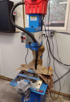
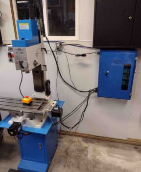
Yes, today was all about getting the milling machine CNC capability online.  Which I was actually successful in doing.

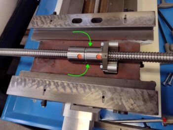
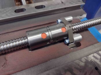
Yesterday I spent much of the day messing about with reinstalling the X-axis ball screw and mounts to allow the stepper motor to actuate the table left and right without getting a Drive OK Fault Alarm… which, while I’m glad the Drive OK Fault Alarm is working properly, I certainly don’t want to see one every time I command a +/- movement on the X axis.

With the drive axes finally working in all directions yesterday, today was all about finalizing the CNC install tasks with a couple of bench tests.  And then documenting my mill CNC efforts up to this point in a video.

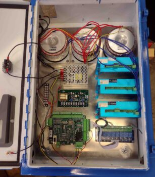
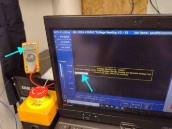
My first task of the day was accomplishing a spindle speed output test on the Acorn CNC control board.  This involves hooking up the Fluke multimeter to the 0-10 volt “VFD” output (I mistakenly call this an “input” in the video…) on the Acorn board.  Since my meter leads wouldn’t fit in the cabinet, I connected two lead wires up to this output.

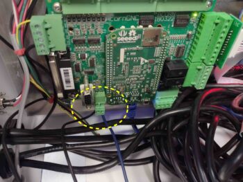
Here are the 2 Acorn board VFD output wires connected to the Fluke multimeter.

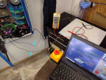
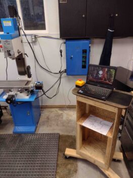
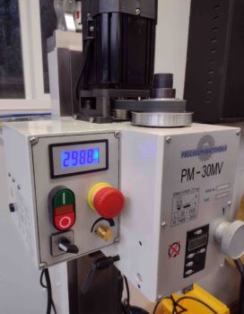
I then loaded up the spindlebenchtest.cnc program into the CNC12 software.

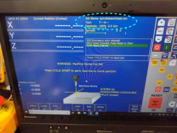
And ran the program.  The program has the Acorn board kick out a series of 4 discreet voltage values which you read off the multimeter display and then enter into the program entry box, one at a time.  This confirms the voltage values between the Acorn board and the CNC12 program to verify all is correct for the VFD voltage output.

This is a prerequisite task that needs to be completed before wiring up the KBSI-240D spindle speed/direction control board, and I figured I would simply get it knocked out now.

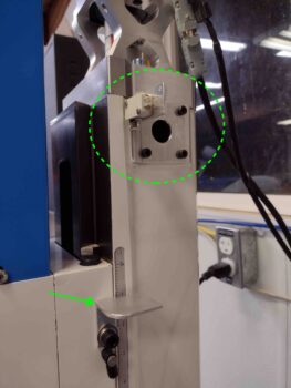
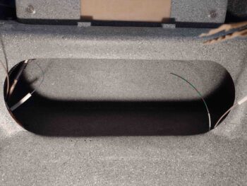
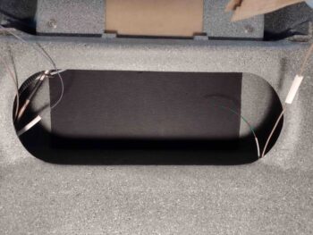
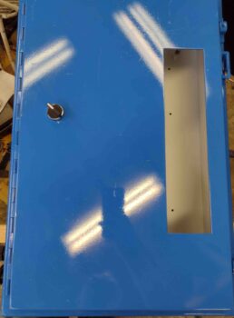
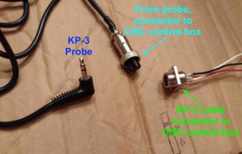
I then unboxed and prepped the KP-3 Kinematic Touch Probe for the bench test that I performed while filming the video.  I figured I would do at least one bench test “live” on camera.

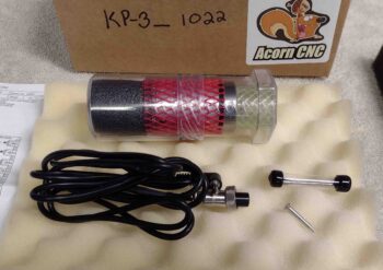
I took the probe body out of its plastic case and then carefully installed the actual probe stylus into the front/bottom of the probe housing.

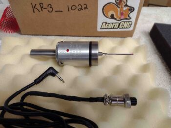
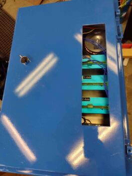
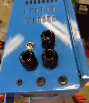
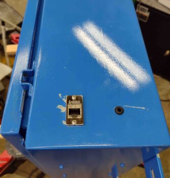
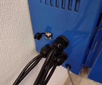
As you can see above, the jack of the probe lead is inserted into the probe body, while the other end is attached to the connector on the outside of the CNC control box, below.

With the KP-3 probe ready to go, I actually filmed the bench test segment first (ah… tricky I am!) before then filming the remaining video footage detailing my mill CNC upgrade machinations.

Here’s the video. It’s a bit long, but I think informative.  Enjoy!

After filming the video, I then of course had a late night of video compilation and editing to get this thing loaded up on YouTube.

Soon I will get back to working on the actual plane… promise!

Chapter 3 – CNC laptop podium

Still no airplane work as I focus on finishing up the major tasks to get the mill CNC capability online.

Part of that capability is to be able to use the primary interface with the Acorn CNC system, which is of course some type of computer.  I will be using a laptop and need a place to set it up for use somewhere in close proximity to the mill and lathe.

So I designed a wheeled-podium to be built all with scrap lumber.  I bought the four 3″ wheels at Harbor Freight when I picked up the grinding disks to notch the mill saddle.

It was quite chilly outside today, but thankfully no rain… I powered through over 4 hours to build this CNC laptop podium/cart, and am quite happy with how it came out.  As you can see, I have a work surface to place my laptop.  I also plan to have a mousepad on the right side and will velcro the E-stop switch to the left front corner.  The shelves will come in handy for miscellaneous stuff as well.

Here’s the front side of the podium.  Again, I used all leftover/scrap lumber to build this guy.

Here’s the wheeled podium inside the shop near the mill & lathe, with the laptop, mousepad and E-stop switch all in the positions I described above.

I then plugged the laptop up to the Acorn board via the included shielded CAT5 cable, but found that after all these years there was apparently an issue with the laptop connecting to Acorn CNC board.  After a good bit of research I ended up completely blowing out all the old Centroid Acorn CNC12 software on the laptop. I then reset/rechecked all the Windows 10 configurations as per Centroid Acorn CNC requirements, and then reloaded the latest CNC12 software onto both the laptop and Acorn board.

It took a few hours and dozens of reboots and power cycles, but I finally got the laptop to synch with the Acorn CNC board with the new software.  I then updated a number of CNC12 program parameters and wrote out a list of a half dozen more that I needed to do more research on.

I then spent about 30 minutes measuring out and designing the front “L” bracket cover for the X axis home/limit switch.  I annotated all my measurements on a sheet of paper to finalize and construct it all tomorrow.

And with a successful software update and login/interface with the Acorn board, I called it a night.

Chapter 3 – Yep, more mill stuff

Not surprisingly, since it’s been a few years since I started this milling machine project, I’ve been watching a number of videos and reading manuals and notes to reacquaint myself with this mill CNC conversion project.

I was looking for info on the pitch of the ball screws to allow me to enter in the appropriate data into the parameters on the Acorn board CNC configuration wizard.  Dave from Arizona CNC made the CNC ball screw conversion kit I’m using, and I’m very pleased with the components and customer service.

Well, one specific question I asked about a couple years back was the clearance between the X axis ball screw and double ball nut assembly and the saddle/table of the mill.  Dave told me that I didn’t need to do any grinding and that it should go right in.  Well, it did.  At least enough to replace the original lead screw mount with the double ball nut attachment mount.  That’s pretty significant in and of itself.

However, I always felt there might be a bit more tension/stress on the ball screw when attached at each end of the table… but didn’t really give it a thought until I was on Dave’s Arizona CNC website poking around for information to populate my Acorn CNC wizard data fields. I ran across a video of Dave machining a notch into the saddle specifically to provide clearance for the X axis double ball nut assembly.   Hmmm?

The area beneath the cylindrical double ball nut is the area of concern (green arrows).

I wasn’t 100% sure if I needed the clearance with the X axis ball nut assembly, but now was the time to grind out this notch to ensure I had the appropriate clearance.  Better to spend a couple hours creating the clearance notch in the saddle now and NOT needing it, then to have the entire system together and then have to tear it all back down to complete this task.

Besides, I strongly suspected that I would need more clearance than I currently had.  With that, I tore the the mill down enough to get access to the saddle.  I then measured and marked the area that I would grind out to provide the clearance notch.

I then got busy grinding out the X axis ball nut assembly clearance notch into the saddle.

I did run out of grinding disks, so I ran out for a couple hours to get supplies, including new grinding disks from Harbor Freight.  I then got back to work.

After grinding out the notch to about 0.2″ at the center of the notch, I then wet sanded the notch with oil and 220 grit sandpaper…. just to smooth out the rough, uneven areas on the surface.

Here’s a shot of the mess I made grinding out this clearance notch in the saddle.

Here we have the saddle and mill all cleaned up, with a new clearance pocket now in existence in the saddle.

Yep, a much better fit betwixt the X axis ball nut assembly and the surface of the saddle. I’m glad I took a few extra hours to complete this mod… I think it will be much needed.

It was early evening at this point, and my goal for the day was to get all the brackets constructed for the X, Y and Z axes home/limit switches.  Of course I had no idea I would be making such a significant detour to create the clearance notch in the saddle.

I pressed forward to knock out as much of the construction of the axes home/limit switches brackets as possible.  I started with the Z axis home/limit switch top bracket and the micro-switch-depressing plate mounted to the headstock.

Here’s another shot of the Z axis home/limit switch components mounted onto the right side column of the mill.

I then knocked out the lion’s share of the components required for the Y axis home/limit switch.  This required actually drilling and tapping a couple of bolt holes into the base of the mill.

The upper bracket houses the actual home/limit micro-switch (magenta arrow) and is mounted to the bottom right edge of the saddle.  It took a fair amount of trial & error fiddling to get this upper bracket installed, but as you can see, I finally got ‘er mounted.

Tomorrow I’ll press forward with the home/limit switches install for all the axes, and then get them wired up to the Acorn CNC board as well.   Additionally, as part of the initial mill CNC capability, I need to construct a wheeled podium for the Acorn CNC laptop to sit atop while it interfaces with the Acorn CNC controller.  I have some initial thoughts on that, mostly revolving around the use of scrap lumber.

Again, once I finish the heavy lifting on the mill CNC capability, I’ll then get back to work on the plane.  After this initial push on the mill CNC, the tasks should be much more manageable and only require an hour here and there to get this CNC’d mill fully operational.

I’ll also reiterate that this mill and lathe CNC capability is solely for the purpose of making components for the Long-EZ (at least initially of course).

Chapter 3 – CNC control box installed

Yes, today was all mill install work.  And as James Taylor wrote, “Mill work it ain’t easy, mill work it ain’t hard . . .  mill work it ain’t nothing, but an awful boring job.

Well, I had a bit of that boring job today as I finally got around to breaking in the milling machine.  As per the manual, you need to run the mill’s motor at 200 rpm increments for a minute at each rpm setting.  Both in forward and reverse.  On both the low and high power settings.

This resulted in about 45 minutes of me reading the milling machine manual and assessing my final mill CNC installation tasks as I ran the milling machine, literally, through its numbers.

I then got busy finalizing the installation of the Fog Buster system.  You can see the actual reservoir in the lower left corner of the pic.  The air/lubricant dispensing nozzle and tubing is in a bag hanging off the reservoir’s left side.  The blue air line, via a solenoid, brings in pressured air from a connection to the shop air compressor.

In the upper right is the physical switch that allows control of the Fog Buster from either the mill or lathe CNC control boxes, respectively.  It also has an OFF position.

I then spent quite a few hours wiring up all the components inside the mill CNC control box.

And then finally got the mill CNC control box mounted to the wall.  I didn’t weigh it, but I would say this control box is easily over 50 pounds… possibly closer to 60, maybe even 70.  The box itself if quite robust, then the toroidal power supplies really add a lot of weight.

I then disconnected the motor drive connections to the Acorn CNC control board to power up the Acorn board to ensure it was getting power.  You can tell by a blue LED “heartbeat” light on the Acorn board if it’s powered up and functioning correctly, even without a PC connected to it.

All looked good.

I then connected up the motor drivers to the Acorn board and test fired that all up with power.  Again, no smoke came out of the wires and all LED indicators looked good.

Note the stepper motor cables wound up and piled into the lower right corner of the box. There’s really nothing down there except the Ethernet port and bank of relays on a board mounted on the back plate.  I left these stepper motor cables full length for now just in case I find that I want to move the CNC control box or for any other unknown future reason.  I can always cut these stepper motor cables in the future, but cutting them now and then needing to possibly lengthen them again in the future would just be a huge PITA.

Here we have the final shot of the evening: the mill CNC control box mounted onto the wall near the milling machine with the stepper motor cables run and installed inside the box.

The small yellow/black box with a red button is the emergency stop (or E-stop) switch that I’ll have on the CNC computer podium (to be constructed) in case of any required quick emergency stop of the CNC milling operation.

Tomorrow I plan on finalizing the install of the home/limit switches and running the stepper motor axes through their paces to verify a good initial install of the mill CNC system.

Chapter 3 – Tooling up: Mill CNC

This blog post covers both today and yesterday.

Yesterday I focused on my Fog Buster system control circuit design and install.  The Fog Buster is both a pressured-air chip-clearing and a lubrication-dispensing nozzle that is set up and aimed at the part being machined, either on the mill or the lathe.

I designed a circuit that would not only allow the milling machine Acorn relay board control of the Fog Buster. but also to switch out control of the Fog Buster between the respective mill and lathe CNC controllers.

Today I got to work mounting the back plate into the control box and then finalizing the installation of all the components onto the control box back plate.  This included the 3 large toroidal stepper motor power supplies across the top, the 3 blue stepper motor drivers down the right side, and the Acorn CNC board down in the lower left corner.

Here we have a shot of the populated control box with the door closed.

Tomorrow I plan on finishing up the wiring inside the CNC control box and hopefully get this thing mounted on the wall.

Please remember, the primary purpose of getting this milling machine online is to make parts FOR THE LONG-EZ!

Chapter 3/24 – Mill CNC & sound foam

Today I started out by knocking out yet another task and getting it off the to-do list before flipping the plane back upright: the final addition of sound-deadening foam on the back wall of the center section spar.

After cutting the final piece of sound-deadening foam, I weighed it in at 1.05 ounces.

I then cleaned and prepped the aft wall of the center section spar.  I had painted it previously before my final decision to add in sound-deadening foam.

I then peeled the paper off the sticky backing of the sound-deadening foam and applied it to the aft wall of the CS spar, as you can see here:

I noted the foam backing paper had a bit of weight to it, so I decided to weigh it as well.  It came in at 0.2 oz, making the actual weight of the installed foam at about 0.85 ounce.

I then got to work on the milling machine CNC control box.  First, I drilled 3 holes at the bottom left corner and then installed grommets into the holes.  These grommeted holes are for the axes home/limit switches, E-stop emergency switch, and spindle direction/speed control cables.

On the lower right side of the milling machine CNC control box I installed an Ethernet port (to connect the Acorn board to the Acorn-controlling computer).  In addition, I drilled yet another hole and installed a grommet.  This grommeted hole is for the Fog Buster cooling and lubrication sprayer control cable, which will allow the Acorn CNC control board to control the Fog Buster sprayer.

Finally, I drilled a hole and then installed the ON/OFF switch for the milling machine CNC control system on the front of the door of the control box.

I then went into the house and fired up the soldering iron to create the CNC control box side connector for the KP-3 touch probe (right side of pic).  In addition, I soldered up the wires to the mating mini 5-DIN connector onto the end of the cable that connects to the KP-3 probe itself (middle & left side of pic).  This completes the cable side connector, whereas I still need to install the actual control box side connector and terminate the wires at the Acorn control board.

Tomorrow I plan to install the milling machine CNC control box component back plate, and then install all the components onto the back plate.  Once these components are installed, I then plan on finishing up the wiring for the entire CNC control box.