
Yes, today was all mill install work. And as James Taylor wrote, “Mill work it ain’t easy, mill work it ain’t hard . . . mill work it ain’t nothing, but an awful boring job.”
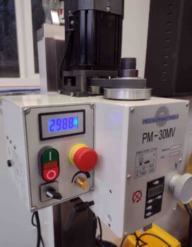
Well, I had a bit of that boring job today as I finally got around to breaking in the milling machine. As per the manual, you need to run the mill’s motor at 200 rpm increments for a minute at each rpm setting. Both in forward and reverse. On both the low and high power settings.
This resulted in about 45 minutes of me reading the milling machine manual and assessing my final mill CNC installation tasks as I ran the milling machine, literally, through its numbers.
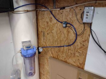
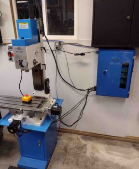
I then got busy finalizing the installation of the Fog Buster system. You can see the actual reservoir in the lower left corner of the pic. The air/lubricant dispensing nozzle and tubing is in a bag hanging off the reservoir’s left side. The blue air line, via a solenoid, brings in pressured air from a connection to the shop air compressor.
In the upper right is the physical switch that allows control of the Fog Buster from either the mill or lathe CNC control boxes, respectively. It also has an OFF position.
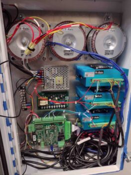
I then spent quite a few hours wiring up all the components inside the mill CNC control box.
And then finally got the mill CNC control box mounted to the wall. I didn’t weigh it, but I would say this control box is easily over 50 pounds… possibly closer to 60, maybe even 70. The box itself if quite robust, then the toroidal power supplies really add a lot of weight.
I then disconnected the motor drive connections to the Acorn CNC control board to power up the Acorn board to ensure it was getting power. You can tell by a blue LED “heartbeat” light on the Acorn board if it’s powered up and functioning correctly, even without a PC connected to it.
All looked good.
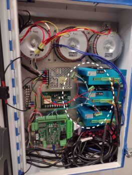
I then connected up the motor drivers to the Acorn board and test fired that all up with power. Again, no smoke came out of the wires and all LED indicators looked good.
Note the stepper motor cables wound up and piled into the lower right corner of the box. There’s really nothing down there except the Ethernet port and bank of relays on a board mounted on the back plate. I left these stepper motor cables full length for now just in case I find that I want to move the CNC control box or for any other unknown future reason. I can always cut these stepper motor cables in the future, but cutting them now and then needing to possibly lengthen them again in the future would just be a huge PITA.
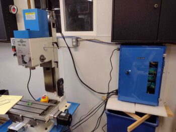
Here we have the final shot of the evening: the mill CNC control box mounted onto the wall near the milling machine with the stepper motor cables run and installed inside the box.
The small yellow/black box with a red button is the emergency stop (or E-stop) switch that I’ll have on the CNC computer podium (to be constructed) in case of any required quick emergency stop of the CNC milling operation.
Tomorrow I plan on finalizing the install of the home/limit switches and running the stepper motor axes through their paces to verify a good initial install of the mill CNC system.