
Not surprisingly, since it’s been a few years since I started this milling machine project, I’ve been watching a number of videos and reading manuals and notes to reacquaint myself with this mill CNC conversion project.
I was looking for info on the pitch of the ball screws to allow me to enter in the appropriate data into the parameters on the Acorn board CNC configuration wizard. Dave from Arizona CNC made the CNC ball screw conversion kit I’m using, and I’m very pleased with the components and customer service.
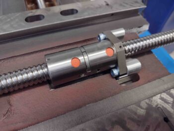
Well, one specific question I asked about a couple years back was the clearance between the X axis ball screw and double ball nut assembly and the saddle/table of the mill. Dave told me that I didn’t need to do any grinding and that it should go right in. Well, it did. At least enough to replace the original lead screw mount with the double ball nut attachment mount. That’s pretty significant in and of itself.
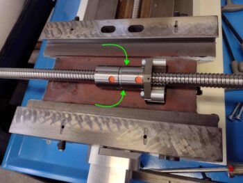
However, I always felt there might be a bit more tension/stress on the ball screw when attached at each end of the table… but didn’t really give it a thought until I was on Dave’s Arizona CNC website poking around for information to populate my Acorn CNC wizard data fields. I ran across a video of Dave machining a notch into the saddle specifically to provide clearance for the X axis double ball nut assembly. Hmmm?
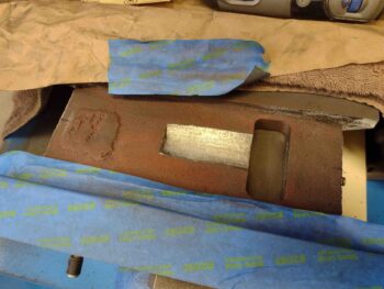
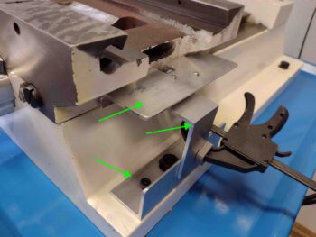
The area beneath the cylindrical double ball nut is the area of concern (green arrows).
I wasn’t 100% sure if I needed the clearance with the X axis ball nut assembly, but now was the time to grind out this notch to ensure I had the appropriate clearance. Better to spend a couple hours creating the clearance notch in the saddle now and NOT needing it, then to have the entire system together and then have to tear it all back down to complete this task.
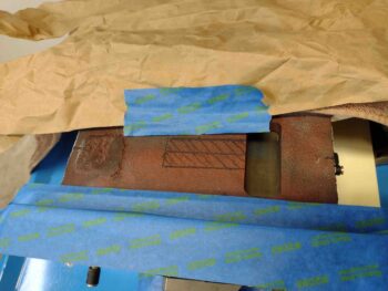
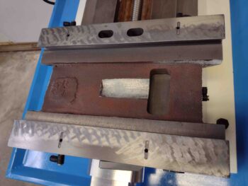
Besides, I strongly suspected that I would need more clearance than I currently had. With that, I tore the the mill down enough to get access to the saddle. I then measured and marked the area that I would grind out to provide the clearance notch.
I then got busy grinding out the X axis ball nut assembly clearance notch into the saddle.
I did run out of grinding disks, so I ran out for a couple hours to get supplies, including new grinding disks from Harbor Freight. I then got back to work.
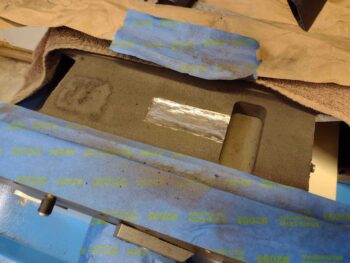
After grinding out the notch to about 0.2″ at the center of the notch, I then wet sanded the notch with oil and 220 grit sandpaper…. just to smooth out the rough, uneven areas on the surface.
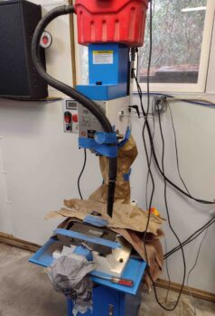
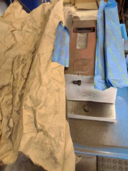
Here’s a shot of the mess I made grinding out this clearance notch in the saddle.
Here we have the saddle and mill all cleaned up, with a new clearance pocket now in existence in the saddle.
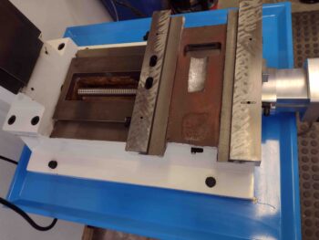
Yep, a much better fit betwixt the X axis ball nut assembly and the surface of the saddle. I’m glad I took a few extra hours to complete this mod… I think it will be much needed.
It was early evening at this point, and my goal for the day was to get all the brackets constructed for the X, Y and Z axes home/limit switches. Of course I had no idea I would be making such a significant detour to create the clearance notch in the saddle.
I pressed forward to knock out as much of the construction of the axes home/limit switches brackets as possible. I started with the Z axis home/limit switch top bracket and the micro-switch-depressing plate mounted to the headstock.
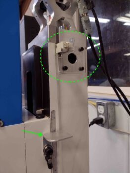
Here’s another shot of the Z axis home/limit switch components mounted onto the right side column of the mill.

I then knocked out the lion’s share of the components required for the Y axis home/limit switch. This required actually drilling and tapping a couple of bolt holes into the base of the mill.
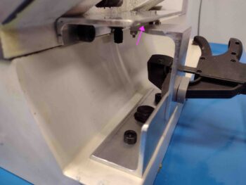
The upper bracket houses the actual home/limit micro-switch (magenta arrow) and is mounted to the bottom right edge of the saddle. It took a fair amount of trial & error fiddling to get this upper bracket installed, but as you can see, I finally got ‘er mounted.
Tomorrow I’ll press forward with the home/limit switches install for all the axes, and then get them wired up to the Acorn CNC board as well. Additionally, as part of the initial mill CNC capability, I need to construct a wheeled podium for the Acorn CNC laptop to sit atop while it interfaces with the Acorn CNC controller. I have some initial thoughts on that, mostly revolving around the use of scrap lumber.
Again, once I finish the heavy lifting on the mill CNC capability, I’ll then get back to work on the plane. After this initial push on the mill CNC, the tasks should be much more manageable and only require an hour here and there to get this CNC’d mill fully operational.
I’ll also reiterate that this mill and lathe CNC capability is solely for the purpose of making components for the Long-EZ (at least initially of course).