Chapter 26 – Final on Seat Cores

I’ve actually been able to get a fair amount done on the first part of my trip, in Greensboro, visiting friends and family.  Since I’m not working on the actual build I figured I would get the Oregon Aero seat cores finalized and get that off the list.

I’ll note that I did get the seat cores, headrests, armrests and heated seat warmers shipped off to Oregon Aero.

My final seat core adventures started of course before I left, as I noted in my last blog post. During the machinations of rooting out the last tweaks required to get an optimized fit for all the seat core components, I wrote out on the whiteboard this list of 9 tasks needing completed:

In no particular order, I’ll show you a smattering of some of those tasks.

First off is the pilot headrest.  The pads on these definitely need tweaking and are not even nor symmetrical.

Here’s a closeup.

And the top headrest pad…. not as bad as the bottom, but still needs some tweaking.

I spent a bit of time making up these templates that I will take with me on my trip out west. Since I’ll be fairly close to Oregon Aero, I plan on stopping in and conferring with them on these final tweaks and my upholstery scheme.  I’ll drop these templates off for them to use if needed.

One issue of rather minor concern is the front seat lower pad gap with the seat back bulkhead.  It’s a decent sized gap all the way across so I put on the list so that they can easily fill it in.

Here’s a quick drawing of the issue going on above.

As for the front seat back cushion, it needs to be just a bit wider.  Right now it will tilt a bit one side to the other and I want it fitting snuggly in between the 2 armrests.  I noted some dimensions along the side for amount required to be widened at that spot.

The last big item on the front seat back cushion is the gap at the very top aft of the seat cushion with the front seat top structure.  The top section of the seat is angled forward just enough to create a noticeable gap here, and I want that minimized as best possible.

Onto the GIB seat, there is a gap between the upper cushion and the bottom cushion that’s notable as well.  So I annotated all the right/center/left dimensions to have this minimized as well.

Since the front edge of the lower GIB seat is peaking out from beneath the cushion, I want another 0.5″ added to the front of the cushion simply to provide the GIB with as much thigh support as possible.

Finally, with the current configuration of the GIB headrest pad it doesn’t allow me to unscrew the top 2 CAMLOCs.  So I’m simply having them shave off the upper “corners” of the GIB headrest pad to make those CAMLOCs both visible and removable so I don’t have to remove the headrest every time I want to gain access to the D-Deck components (i.e. GRT EIS, etc.).

All told I spent a good 3 hours writing these tweaks up in detail to the folks at Oregon Aero to ensure the final mods were done in optimized fashion.

Moreover, I then spent another few hours finalizing my color choices and my upholstery scheme and sending that off to Oregon Aero as well.  For the upholstery, ya’ll will just have to wait for the big reveal to see the colors and design! (grin)

Chapter 13/21/22/24/26 – Seats, etc.

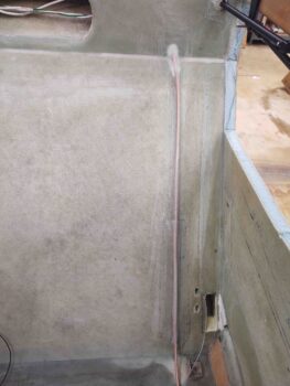
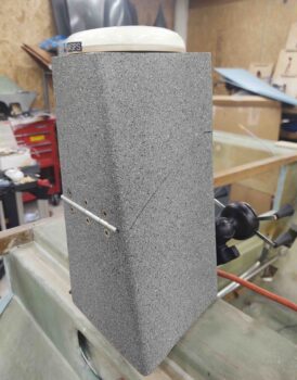
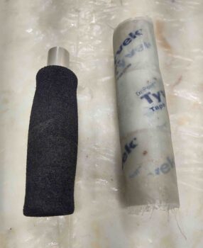
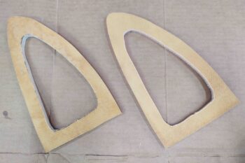
I started off today with a quick pulling of peel ply from the strake OD ribs outboard side one ply BID layup.  All looked good so I chucked them on the pile of other strake ribs and baffles and pressed on.

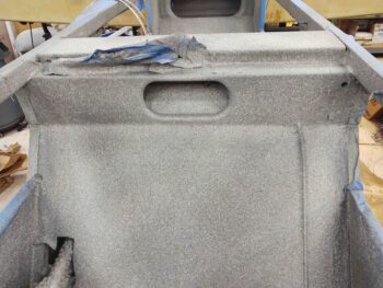
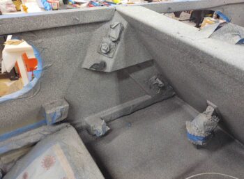
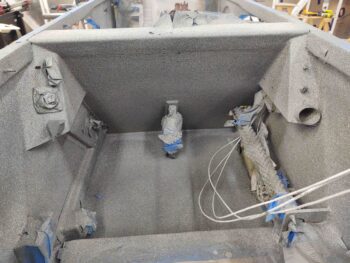
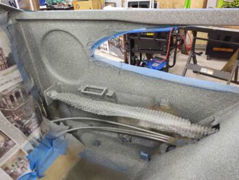
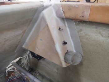
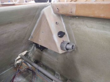
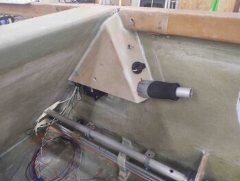
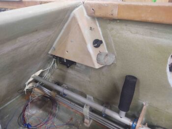
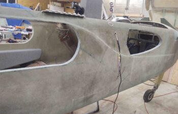
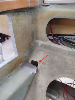
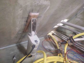
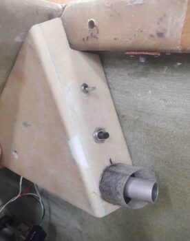
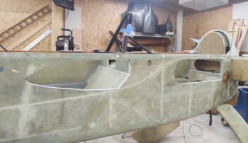
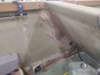
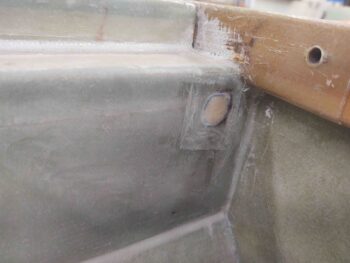
Since I’ll be out of town for a couple weeks starting tomorrow I really didn’t want to start in on the strakes since I still need to finish off the aft nose/avionics cover attach points.  So today was all about the 4 CAMLOC hardpoint tabs along the front edge of the aft nose cover, only focusing on the nose bridge tabs first.  These tabs will simply have holes in them where the CAMLOC/SkyBolt stud will fit through and lock into the CAMLOC/SkyBolt receptacle attached to a front interior lip (which at this point does not exist) of the aft nose/avionics cover.

My first decision point was that there would in fact be 4 CAMLOC attach points, positioned in spots where the mating points on the cover could swing down and clear the canard (for the outboard points) and that I could access them easily enough over the top of the NG30 (for the inboard points… note NG30 set back in place to check clearances). I’ll point out that these hard points are NOT symmetrical about the nose centerline since the cover’s hinges both attach on the right side of the hinge mounting tabs.

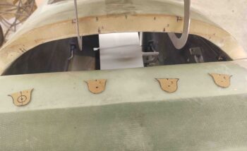
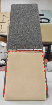
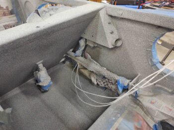
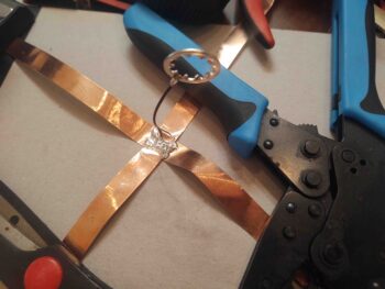
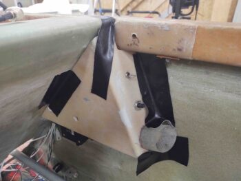
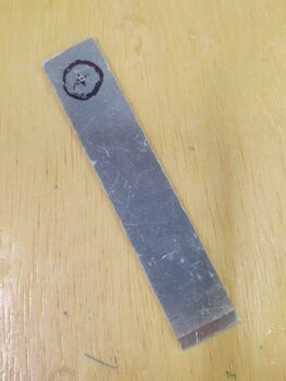
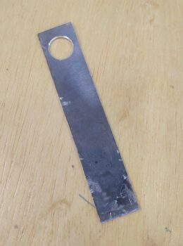
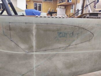
I then designed the CAMLOC hardpoint tabs with enough clearance around the stud hole to be strong enough to secure the front edge of the aft nose/avionics cover (above).  I then cut each tab out of 1/16″ thick G10 and sanded down each side for texture to get good bonding for glass.  I also pre-drilled a small starter/alignment hole at the hole center of each tab.

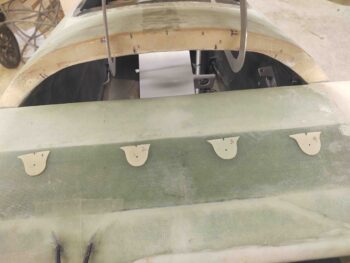
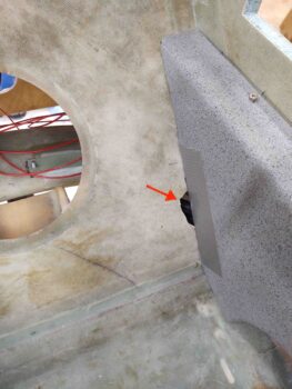
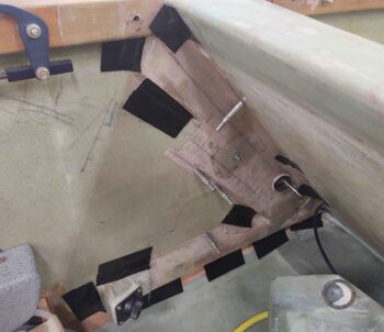
To ensure the tabs were an straight-line extension of the aft edge of the nose bridge, I taped a short length of a big popsicle stick to each tab.

I then 5-minute glued just the top edge of each tab to the underside edge of the nose bridge.

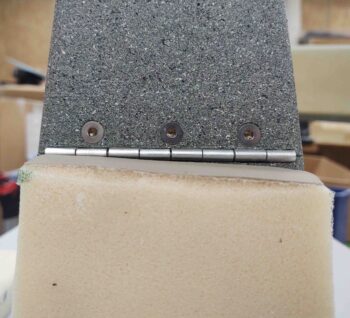
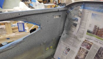
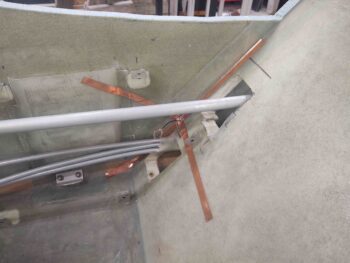
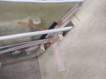
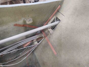
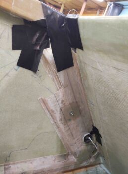
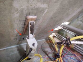
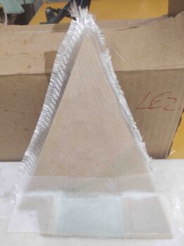
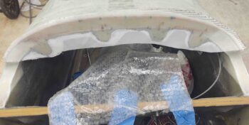
I let the 5-minute glue cure for about a half hour while I made a template and then subsequently cut out a ply of BID for the entire nose bridge aft face, including the newly mounted CAMLOC tabs.

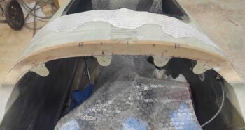
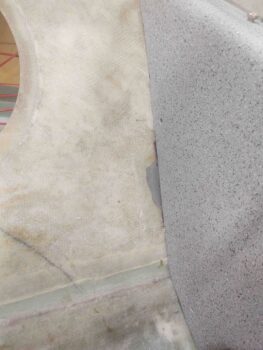
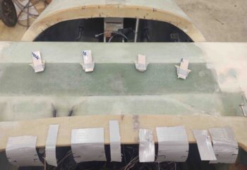
After cleaning off the scant bit of excess 5-minute glue on each tab/nose junction, and also creating flox corner edges in the exposed foam on each side, I then laid up the ply of BID.  I then peel plied the layup.

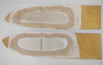
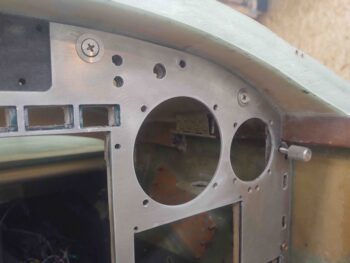
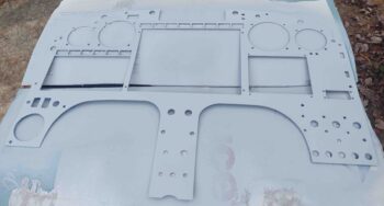
I had already filled a few of the small divots and rough hole edges in the instrument panel with Metal Glaze. Since it was another nice weather day today, after one final good wet sand and acetone wipe down of the panel I took it outside and hit it with a couple of coats of primer.

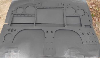
I then shot the instrument panel with 3 coats of SEM black.  I know it looks more dark gray in the pic, but in person it looks black.  And although I don’t show it here, I then took the panel inside and baked it in the oven for about 1-1/2 hours at 175º F.

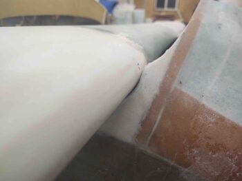
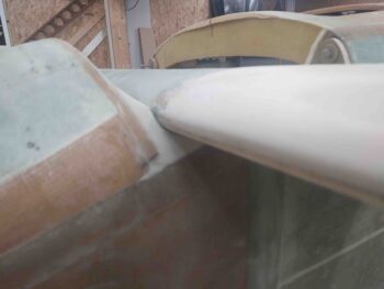
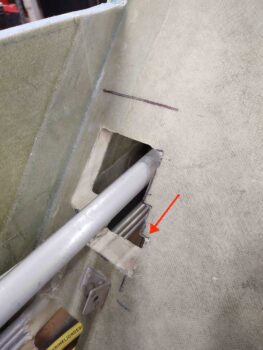
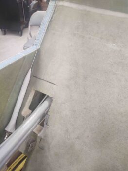
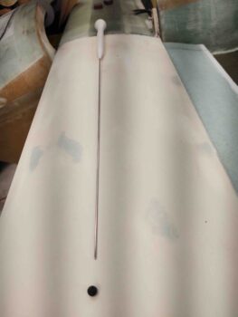
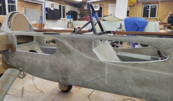
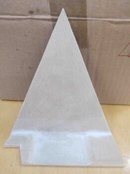
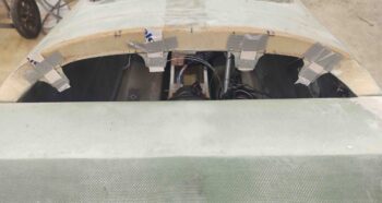
A few hours later I pulled the peel ply on the aft nose/avionics cover front nose side CAMLOC tabs.  I then did a quick razor trim on the edges.  I’m really happy that the tabs are installed and aligned with the nose bridge cross face, and also that I no longer have any exposed bare foam in the upper nose area around the canard.

When I return from my trip I’ll finish securing the tabs by laying up a ply or two of BID on the front face of each tab that overlaps onto the underside of the nose bridge.

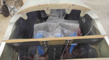
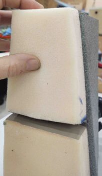
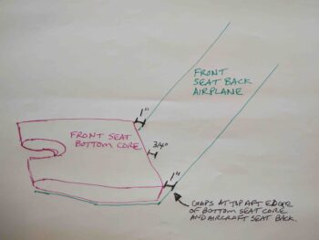
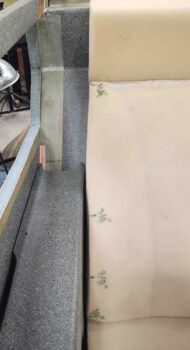
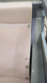
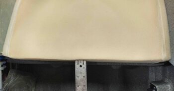
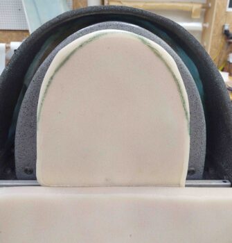
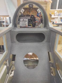
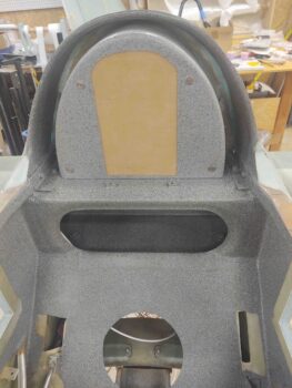
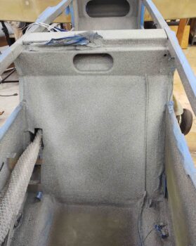
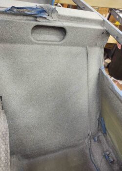
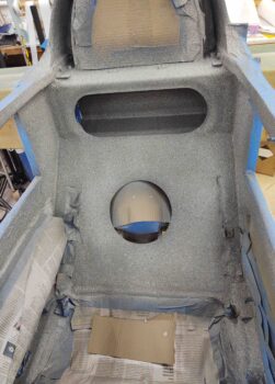
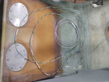
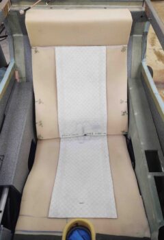
The next phase of the evening was all about the Oregon Aero seat cores.  I put the seat cores back in place place in the fuselage to do one thorough final assessment of how they fit before I send them back to get upholstered.

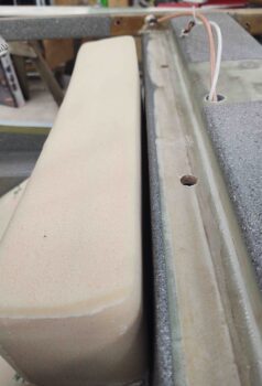
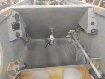
This also gave me a chance to do a quick knee clearance assessment on my GIB side sub-panels.  I’ll remind ya’ll that I’m a long-legged 5′ 11″ tall, so I consider myself right at the max height for someone to travel comfortably in my back seat on a longer trip.  Any shorter heights than me should be fine comfort wise.

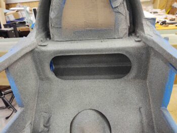
With my feet placed at a comfortable mid-point on the floor board, my knees are actually behind the sub-panels and rest quite comfortably on the fuselage sidewall.

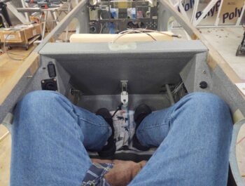
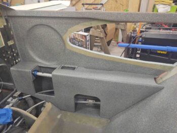
However, if I move my left foot forward to just aft of the pilot’s seat, my leg just below the knee rests on the edge of the left side sub-panel.  It’s not horrible nor is it digging into my leg, but I wouldn’t want to keep my leg at this position for a considerable length of time. Not optimum, but not horrible either.

Conversely, the right sub-panel is no factor since it is narrower than the distance that the control stick tube is from the sidewall.  Thus, my leg rests against the control stick tube before it makes contact with the edge of side panel.  Clearly this what I had envisioned for both sides, but the left didn’t make the grade.

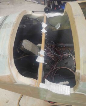
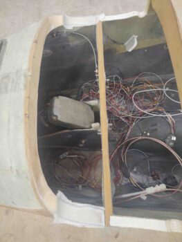
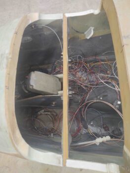
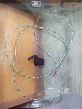
I then went into the house and spent a good hour referring to my heating systems electrical diagram to hook up first the front pilot seat seat warmer pads to test them out, and then the back GIB seat seat warmer pads to test them out.  I’m happy to report that they both worked fine on both the high and the low settings.  Not surprisingly, the low setting was just that, a bit warm.  Whereas the high setting got warm very quickly and after a few minutes I was ready to turn them off.  Grant it, that was in a 69º house, but still a good showing on both sets of heated seat warmers.

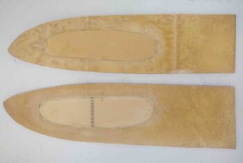
I then took the seat warmers out to the shop and fit both the front and the back sets to their respective seats.  The front seat warmer pads needed a few inches cut off both the top seat back pad and the bottom seat pad, whereas the back GIB seat warmer pads didn’t require any trimming.

Since the folks at Oregon Aero will install these heated seat warming pads into the seats as they upholster them, I also marked the seat warmer pads to show which pad goes where, and the direction of the wiring exits [front seat pad wires exits left, whereas aft seat pad wires exit right].

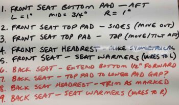
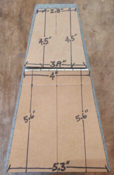
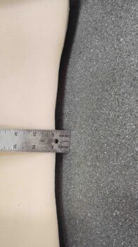
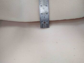
I then spent well over another hour taking pics of the seat cores and annotating the final tweaks that will need to be made to the cores and headrests before they get upholstered. I then boxed up all the seat cores, headrests, armrests and heated seat warmers in the original Oregon Aero box to have it ready to ship out Friday back to Oregon Aero.  I’ll also write up a detailed email to Oregon Aero identifying all the required latest tweaks that need to be made to the seat cores and headrests.

Thus ended my final night work on the build for 2+ weeks.


Chapter 13/21/26 – Industrial Chic

That’s what I’m calling the interior style of my plane . . . ha!

I had originally planned to take my vehicle in for an oil change and to get inspected at a place in Greenville on the way down from DC last weekend.  However, with road construction delays I had to cancel my appointment and reschedule for today.

The weather temperature high today was only 58º, but I call that good enough for clear coating!  But I needed to wait until mid-afternoon for the weather temp high to be reached, so I needed a task that wouldn’t take too long and preferably one that had been on the “to-do” list for a while: I decided to layup the bottom/LE canard contour in the nose just forward of F22.

I started off making my angled cuts along the edges for a nice flox corner, and then assembled and cut my BID glass (all scraps, of course).  The small pieces of BID are for building up the thickness at the front of the contour to bring it closer to vertical, and closer to the canard LE.

I then laid up the BID and peel plied it.

I took a very short break and then pulled the fuselage back out of the shop and proceeded to clear coat the cockpit paint I shot yesterday.

This stuff is dry –but not usable– within a good 20 minutes, so I carefully but expeditiously removed the blue painters tape.

This gives you an idea of what the cockpit will look like when finished.

Moreover, this area here, the back of the pilot’s seat and the GIB floor, is the primary reason I wanted to paint the cockpit at this stage.  As challenging as it was to paint with no strakes and access-providing sidewall openings, I can’t imagine painting all this with strakes on!

Here’s looking aft at the back seat and D-Deck.  You might note that the area around the GIB headrest is not painted.  I taped that off since I’ll be mounting the fuel tank vent lines back against the front face of the firewall that will then loop up, over and around the headrest to vent on the opposite side of the D-Deck vs the tank side (i.e. left side vents for right tank).

I then left for my auto appointment in Greenville, which is nearly 1.5 hours away.  It took them about 2 hours to finish up, so all told I was gone about 5 hours today.

When I returned I pulled the peel ply off the nose contours for the canard bottom/LE.  I then razor cut and cleaned up the edges of the glass.

I then re-installed the canard to check the fit…. I’m very pleased with how these layups came out.  I’ll tape up the canard LE and then use micro to tighten up the gaps between the canard and the nose contours.

To check out more of the cockpit paint, I then re-mounted the GIB headrest/D-Deck cover plate.

I then rounded up the front seat right armrest and set it in place as well… I’m loving this paint!

Finally, I set the GIB left armrest in place.  I’m finding little areas that will need paint, tweaking, etc. when I do cockpit paint round 2 after the strakes are installed.

You may note some slight color variations of the armrests, GIB headrest plate, etc. with the freshly painted cockpit.  IMO this paint is a lot like Candy coat paint: it’s a bit finicky and the final color, depth and shade solely depends on how many coats you apply.

Starting out I was more concerned about paint weight, so I did a coat or two less than I just did on the cockpit.  Lacking the OCD affliction that so many home builders have, and I know I’m weird, but I like the story that the slightly different shades of components tell. We’re building hand-carved airplanes here, so a little variance is a good story in my book!

My last task of the evening was laying up a ply of BID on the outboard side of the strake OD ribs.  Since I’m making the inboard side now a fuel cell (the forward part), I glassed it using EX-Poxy.  But since the outboard side doesn’t touch fuel, I’m using the way easier (to me) MGS 285 epoxy.

That being said, I did spend a good half hour prepping the ribs to remove dead micro, etc. to get these ready for glass layups.

About 1.5 hours later I had the 1-ply BID glass laid up and peel plied.

And with that, I called it a night…


Chapter 26 – Initial Cockpit Paint

I started off today pulling the peel ply and cleaning up the layups on the GIB left sub-panel.

With no rain and a high of 67º forecasted, I then got to work sanding, prepping and taping off the cockpit for paint.  I missed my target time by a few hours, but I was still able to get this guy out the door, apply a couple of medium coats of primer followed by a couple coats of Rustoleum gray stone paint (just like the canopy and armrests).

The rest of this post is simply a smattering of shots of the painted interior cockpit.  Here we have the front seat area.

And the GIB area, including the newly mounted side sub-panels.

And the pilot seat sidewalls.

And the back seat.

If the weather holds in the next day or so I’ll clear coat the paint with a matte clear.


Chapter 22/24 – Function over form

Unfortunately I wasn’t able to finish the cockpit components in time to get the interior cockpit painted.  But why am I so hellbent on painting the cockpit now?  Well, I especially want to get the back seat area painted so I don’t have to lay on the strakes to do it later. In addition, with the cockpit painted (all except the edges of the strake openings since strake-securing glass will overlap a bit onto the interior sidewalls) I will then run the majority of the electrical cable/wire runs down the inside of the fuselage while I have the easiest access I’ll have during the build.

Thus why my push to get all the internal cockpit components installed and prepped for paint.

So where yesterday was marked by a lot of electrical oriented work, today was all glass layups.

I started by laying up 1-ply BID tapes on the perimeter of the GIB right sub-panel to secure it into place.  I then peel plied the layups.

As the right GIB sub-panel layups cured, I then got to work on pulling peel ply and cleaning up the final layups on the GNS-480 GPS antenna cable.  Apparently I forgot to grab pics or report on my GPS antenna cable progress, but here it is in its final state before the cockpit gets painted.

Again, with MGS epoxy it’s hard to tell, but there’s a ply of BID securing the GPS antenna cable from the bottom of the pilot seat back bulkhead to the top where the cable enters the seat back structure/rollover base.

I then worked for a number of hours on the final configuration of the LEFT GIB sub-panel. I had to flatten the install angle of the USB charger to align it more parallel to AC centerline to get better clearance with the canopy latch rod.  I also made up 4x 10-32 phenolic nutplate assemblies and mounted them on the underside of the sub-panel for the eyeball vent-securing screws. Again, I was in such a mad rush to get all this done that I failed to snap any pics.

Before I got around to glassing in the LEFT GIB sub-panel, I pulled the peel ply and cleaned up the layups on the right GIB sub-panel.  Here it is with the GIB removable control stick in the stowed position.

And a shot with the control stick nearly out of its stowage tube, to show that I made the diameter of the tube just a tad smaller than the diameter of the foam grip on the control stick so that the tube grips the control stick firmly.

Although I removed the control stick assemblies in prep for paint, here I’ve mocked up the GIB control stick in place.  I’ll note that I tested and double-checked the clearance between the control stick, and during use, with the aft lower edge of the right GIB sub-panel.

While I’d say I’m very happy with the right side GIB sub-panel, I’d say I’m somewhat happy with the left GIB sub-panel.  I’ve already stated in practice I’m not a big fan of these side sub-panels, and if it weren’t so late in the game and I hadn’t set the position of the upper GIB air/heat vent via the main duct system, I’d have reworked this side sub-panel, especially after this last issue.

My mockups went well, but it’s hard to tell exactly how all will fit until the rubber meets the road when you do the final install.  With the clearance, or lack thereof, with the components and especially the interconnect SCAT tube from duct to eyeball vent, to keep the inboard wall of sub-panel vertical and not angled inboard I had to come off the sidewall over 1/2″ (note the strip of green 0.063″ G10 that I 5-min glued, floxed and glassed in place). Again, this late in the game I was just not going to redo this panel and start over… my decision was to salvage what I had and press forward.  And yes, it does translate into a little less knee room for the GIB.

My first issue was the angle of the sub-panel face is a good 5-10º too steep off the sidewall.  I should have made it more perpendicular to the sidewall.  By not having a shallower angle it made the components face too much outwards vs parallel to AC centerline. This had them pressing into the duct and minor clearance with the canopy latch rod.  I expected to have to bring the sub-panel off the sidewall about 1/4″ max, but not over 1/2″.

[Note: during the layups the USB charger cap is not in place, but hanging down farther than normal. This makes it look like its both installed closer to the eyeball vent than it actually is, and also off-kilter in the last pic.  Future pics will show this better.]

My blog post title, “function over form” alludes to the placement of the components in the sub-panel.  I didn’t just throw these chargers and eyeball onto the face of the sub-panel willy-nilly, but rather had to configure them to avoid what lurks underneath: the alignment of the eyeball vent with the duct behind/underneath it, and the vertical & inboard placement of the USB charger to keep it from interfering with the canopy latch rod.  A horizontal placement of the USB charger was out of the question, and if I tried to move it up any higher it would collide with the aft surface of the pilot seat back.

So it is what is, functional but not perfect.  I’ll throw some lipstick on this pig by painting it and press on…

Ironically my buddy Dave Berenholtz recently commented on how nice I was being to the GIB by installing a bunch of this stuff, so I guess just to prove him wrong I extracted some knee room from them! (grin).

I may have missed my immediate window for painting the cockpit, but looking at the weather it’s supposed to be a nice day this coming Wednesday.  The next couple of days are supposed to be rain, so unless the forecasts are wrong, Wednesday will be my new target day for painting.


Chapter 22/24 – Cockpit prep (cont.)

Today was pretty much all about electrical stuff, in prep to try to get the interior cockpit painted while the weather is good.

I started off creating a 16″ x 16″ plus sign out of copper foil tape for the ELT back plane. I started with one 16″ long strip of coper foil tape, and then added two 8″ pieces to it with a small gap in between them.  I then simply added solder to all the edges and I got me an ELT backplane.

I then soldered the high-grip washer that came on the ELT antenna to a wire, and then soldered the wire to the copper foil strips.  This will give me the required electrical continuity between the antenna mount and the backplane, as per the ACK E-04 manual.

I then installed the ELT copper foil backplane into the right corner of the pilot seat. If you think the right angles for the backplane are incorrect, well, then you’d be incorrect… hehe. According to the owner and lead bubba at ACK, right angles like this are perfectly acceptable for a backplane.  The big concern is actually having a backplane in a composite aircraft!

I then covered all the copper foil legs of the ELT backplane with a ply of BID.  A fair bit of which I peel plied.

Jumping ahead a few hours, here’s the cured overlaid BID on the legs of ELT antenna backplane . . . yes, with MGS epoxy it’s hard to tell that there’s anything there.

During the copper foil tape protective BID layup I added a couple plies of BID just below the crosspoint of the 4 backplane legs, and when it cured I floxed in the ELT antenna mounting bracket (in pic above too).  Here it is a few hours later after the flox cured, with the antenna in place for a test fit.  I think this dawg will hunt….

One of the many things I’ve pondered over the past few years was exactly how to run the GNS-480 GPS antenna cable from the panel mounted GPS to the pilot headrest-mounted GPS puck.

Here’s a shot of the GNS-480 GPS antenna cable when the pilot’s headrest is opened to access storage.

I finally decided that instead of punching through the back of the pilot’s seat at a low(er) point just to have the cable re-enter again towards the top, I would run the GPS antenna cable up the front face of the pilot seat bulkhead.  I have it positioned so that it is right at the edge of the seat cushion. just barely covered by it.

I don’t like making things inaccessible in case they need maintenance or repair, but I figured this cable is fairly low on the failure scale, so I simply glassed it to the front face of the pilot’s seat with a ply of BID.  This is the first of a few piece of BID that will secure the GPS antenna cable to the front seat back.

I then got to work selecting some 16 AWG wire and building a cable for the GIB cigarette lighter style charger.  I also printed off some labels and labeled the wires and the cable.

I then did the same thing with some 20 AWG wire for the GIB USB charger unit.

I then ran the wires from the USB and cigarette lighter chargers from the left GIB sub-panel over to the right side and out a hole I drilled in the pilot’s seat back just forward of the roll trim actuator pad.

I then grabbed the GIB right sub-panel and ran 2 sets of wires: The first went out the side wall to power/control the GIB map light.  The second was the GIB lights power and ground wires that go forward to the TriParagon.

Also note that I 5-min glued the relay to the interior side of the right GIB sub-panel.  I then had a small strip of 1-ply BID left over from the ELT antenna backplane layup, so I used it to help secure the relay to the inside surface of the sub-panel, just behind the switches.

In addition to the the chargers on the left GIB sub-panel, I also routed the cables for the fuel site gages video cameras.  The left side cable transits through the pilot seat back, while the right side comes straight in through the side wall.

BTW, I just today glassed in the clickbond that the adel clamp is mounted to.

Here’s the left side fuel site gage video camera cable.  This cable also includes the power leads for the fuel site gage LED.

Here’s the wires exiting the fuselage on the right side into what will be the interior wall of the strake baggage compartment.  These wires are for the right fuel site gage video camera, the power wires for the fuel site gage LED, and the wires for the GIB map light.

My last task of the evening, as it was getting late, was to 5-minute glue the right GIB sub-panel into place.  As you can I secured it in place (after holding it in place for quite a few minutes) with Gorilla duct tape.

I then let the 5-minute glue cure overnight as I called it a day.

Chapter 22/24 – Cockpit Paint Prep

The weather is supposed to be acceptably warm (mid-70s) over the next 2-3 days so I’m rushing as fast I can to finish up the interior tasks in the cockpit so I can paint.

On the heat/air duct I needed to reseal a couple of spots that didn’t quite pass muster. There was one strip towards the bottom, but most of it the areas of concern were all at the top.

I re-silicone RTV’d the flanges and then taped them as tight as I could get it.

I then started some seat back hole filling along the edges of the armrests, both on the front seat (red arrow).

The upper right GIB seat . . .

And the lower left GIB seat.

I also filled the back side of the through-seat hole edge on the back of the pilot seat, as well as installed a clickbond to secure the landing brake cable with an adel clamp.

After all these years I’ve finally decided where I’m going to mount my ELT antenna.  For a very long time I had it in my mind that it would go near AC centerline on the back of the pilot’s seat, right next to the landing brake actuator.

The problem was/is that the angle of the antenna connector did not flow well at all with the seat.  So I decided to put it at the very right edge of the front seat, only flipped around backwards to get a better angle for the antenna cable connector (I called ACK and made sure it was ok to do so).  Here’s the general location of where the ELT antenna will be installed.

Once the strakes are installed, I will need to re-glass the edge of the front seat bulkhead where it meets the fuselage sidewall.  At this point I intend to simply cover the ELT antenna with a ply or two of glass right at the very edge of the seat bulkhead.  I also plan to drill a small hole in the pilot seat back structure and hide the top of the antenna in the side back.

To do that, I want the smallest, most nondescript hole I can make.  But the ELT antenna has a protective black ball on the tip.

But a few minutes later, it didn’t (grin).

As I was glassing the various unsightly blemishes in the cockpit, I also laid up a ply of BID on the back of the GIB control stick storage tube as a stop to keep the stick from sliding in too far..

I then spent a good hour+ floxing the GIB removable control stick storage tube into the GIB right sub-panel.  I used a good bit of micro as well and a few plies of BID to secure the stick storage tube.

Here’s another shot.

A couple hours later I pulled the peel ply and cleaned up the interior cockpit cleanup layups.  Here’s the shots of all those:

I then started constructing the ELT antenna mounting bracket.  If you’re wondering why I’m messing with the ELT right now, it’s because I need to install 4-6 copper foil tape strips to create a back plane for the ELT antenna.  At least 2-3 of these backplane strips will attach to surfaces that I plan to paint on the pilot seat bulkhead.

To get this task done, I needed to know the actual mounting position and configuration of the ELT antenna.

Here’s another shot of the ELT antenna mounting bracket…. I actually did a lot more on it, but, alas, I forgot to grab any more shots.

I then mocked up and test fitted the GIB right sub-panel.  Again, if you’re wondering why I went through the trouble of making a storage tube for the GIB control stick, it’s because I don’t like “gear afloat” (as the Navy would say) in the cockpit.

In fact, there’s a funny story (now) of me in the back of Marco’s Long-EZ trying to maintain a climb as Marco punched in waypoints in the GPS.  He asked me what was up since my climb was quite anemic and we were at risk of overspeeding the prop.

Well, as I was moving stuff around in the back seat, the control stick fell out of the strake baggage area onto the floor: game over.  There was no way I could retrieve it… my climb angle was so weak because I was using my finger in the control stick nub trying to lever it back as far as possible.  Unfortunately my finger didn’t work as well as a stick handle!

I then spent a good hour tearing down and removing the panel.  Before the panel actually came off however, I decided to try out my new shorter SkyBolt/CAMLOC studs on the right side of the panel.  The far right stud is a -8, while the one towards the center is a -9. Clearly these fit much better than the -10s I had before.

I’m going to try my hardest to knock out all the interior cockpit tasks so I can get the cockpit 80-90% painted tomorrow . . .  in the good weather!

Chapter 21/22/24 – Strake openings cut

For today’s blog I’ll cover a little of yesterday’s build events as well, no matter how light it may have been.

Yesterday I was just plain beat from this past weekend.  I guess you would call it more of a planning day: not only for the airplane build, but for my upcoming trip out west as well.  I did spend a few hours re-printing all the wiring diagrams that needed printed… which required some updates on a few them.  I will also note that it was quite a chilly day too.

As for today, I spent about 2 hours marking up the sides of the fuselage –as per plans (all but the rounded front tip)– for the strake cutouts.

Here we have the front left fuselage strake cutout marked up.

And the aft left strake cutout as well.

I then cut out the strake openings in the fuselage, ensuring to cut just a hair inside the line to sand a smooth line afterwards.

I’m doing what I call the “Steve Volovsek Elbow Room Mod,” which I learned about from my buddy Marco.  Instead of starting the aft side of the GIB strake opening 15″ forward of the CS spar, as per plans, you start the opening way aft: mine is 5″ forward of the spar. As the name implies, this mod allows the back seat passenger to rest their arms inside the strake openings, which really opens up that area back there to help reduce the feeling of confined quarters and adds quite a bit of comfort for the GIB.

As a pittance of a counterbalance however, I did move the rounded front edge of the GIB strake opening aft 1.5″ to end up at 28.5″ forward of the spar, vs. the plans 30″ forward of spar.  I figured this would add back in just a skooch of rigidity without any really access room being lost.

[BTWMike Beasley incorporated this in his recently airborne Long-EZ, and Ary Glantz followed suit]  I myself have been planning to incorporate this mod since very early on in the build.

I then did the same thing on the right side.  Here’s the fuselage front strake cutout marking.

And here’s the right side fuselage strake cutouts, which completes this initial task for the strakes. Again, I still have to sand the cutout edges to get them dialed in nice, straight and smooth.

After finishing the strake cutouts, I finally got around to pulling the peel ply and cleaning up the GIB right sub-panel interior layup.

I didn’t have a pic of this earlier, but this is the storage tube for the GIB removable control stick.

I actually took a cardboard tube and wrapped it around the GIB control stick, and then taped it up.

I then laid up a bunch of small pieces of scrap glass onto the taped tube, and peel plied it. Here it is with the peel ply removed.

And with the taped, and untaped, control stick removed.

Here’s the taped cardboard tube form, the GIB control stick stowage tube, and the GIB control stick.

Here we have the GIB control stick in the stowage tube.

Before I cut out the strake openings in the fuselage, I tested the saber saw bit on one of the included strake outboard ribs.  With a nice clean cut on the outboard rib, I then proceeded forward with using the saber saw for cutting out the fuselage strake openings.

After the strake openings were cut out, I then went back and cut out the middle area of the other strake outboard end rib.  On both ribs the width of the remaining rib material is about an inch.

I’m adding these access holes since I don’t want a solid rib staring me in the face when I remove the wings.  On the outboard end of the left strake I’ll have 2 GRT magnetometers mounted: One for the HXr EFIS and the other for the Mini-X EFIS.  Clearly I’ll need access to those.

On the outboard strake on the right side I need an accessible pocket in case my nose mounted transponder antenna is causing noise issues (an oft-reported clicking with new S-mode transponders) and I need to remount the transponder and/or antenna.

Chapter 22/24 – GIB area ducts

Due to traffic, road construction, etc. I got back much later last night than I had intended to.  Since I didn’t really have any groceries, I dumped my stuff in the house and grabbed a bite to eat out.  When I got back home I called it a night.

I started off today checking out the heat/air duct mounting in the GIB area just aft of the pilot seat on the left side.  As a reminder, I used silicone RTV to mount the ducts just in case I ever need to remove them.

After removing the clecos and duct tape, I did a quick clean up on some of the more obvious areas, and assessed the duct system attachment to the interior fuselage.  Overall, I’m really pleased.  There are a few minor areas that I’ll need to redo, but nothing major.  In short, the ducts are definitely attached securely.

I then got to glassing the interior of the right GIB sub-panel.  I used an added ply of BID on the depression where the 2 switches will get mounted, and then used a couple of overlapping scrap plies of BID for the rest of the interior surface.

My friend needed me to watch her kid for a few hours, so my little buddy came over to hang out.  I was just finishing up the layup above, and was able to get the interior of the left GIB sub-panel shaped (sorry, forgot to get a pic).  I’ll glass that sub-panel tomorrow.

I did get back out to the shop later in the evening to pull the peel ply and razor trim the right GIB sub-panel once the glass had cured.

Chapter 18/22 – Heat duct installed

I only spent a couple of hours in the shop today before I took off to head up to Northern Virginia for the weekend to visit friends.  I hadn’t planned on going up this specific weekend but some events are going on that made it the time for my annual pilgrimage back to my old stomping grounds.

I actually plugged and glassed the oversized gaping hole that was in the pilot seat back for the canopy latch rod that traverses through it.  Yes, this was more of a cosmetic task but since this is a fairly visible spot I wanted it cleaned up before the cockpit gets painted.  In addition, I peel plied it to make the glass edge transition as smooth as possible.

Moving forward, I’ll simply re-drill a better sized hole for the canopy latch rod.

One big task I wanted to complete before heading out for the weekend was mounting the heat/air ducts in the GIB area just behind the left-side pilot’s seat back.  After my “4-task” prep yesterday, I did a final prep on the fuselage side surfaces and the contact edges of the ducts.

In case I ever need to remove this duct structure for any reason in the future, I used silicone RTV to mount it in place.  The clecos do a pretty good job of holding it in position, but to ensure the duct edges were pressed as firmly as possible up against the fuselage/seat back surfaces as it cures I used Gorilla duct tape to secure the ducts in place.

This will give me a good multi-day cure on the silicone (although 24 hours is a good full cure period) to have it nice and rigid when I go to paint the cockpit.  Moreover, should I need to scrape, remove or clean any silicone that is along the edges –to ensure it doesn’t thwart good paint adhesion– it will be good that it had a few days to cure and be nice and solidly fixed in place (hopefully!).

I was coming up against my scheduled time for leaving out, and had planned on glassing at least one of the two GIB sub-panels.  After assessing the required panel thickness for the 2 switches (one toggle, one rotary) that I’m mounting on the left side GIB sub-panel, I thinned the foam out in the spot where the switches will go.

Since this foam is only 1/4″ thick to start, I took it down around 0.1″ of foam left. Unfortunately, I ran out of time and didn’t get to glass the interior side of this sub-panel. When I return I plan on glassing a ply of BID on just the area where the switches go, then a ply of BID over the entire interior surface of the sub-panel.

To mount the cigarette-style charger on the right side GIB sub-panel, I’ll need to do some similar foam thinning as I did here on the left side.  It shouldn’t take that long, but with cure cycles I don’t expect these sub-panels to be ready for mounting into the fuselage until mid to late Tuesday.