
Unfortunately I wasn’t able to finish the cockpit components in time to get the interior cockpit painted. But why am I so hellbent on painting the cockpit now? Well, I especially want to get the back seat area painted so I don’t have to lay on the strakes to do it later. In addition, with the cockpit painted (all except the edges of the strake openings since strake-securing glass will overlap a bit onto the interior sidewalls) I will then run the majority of the electrical cable/wire runs down the inside of the fuselage while I have the easiest access I’ll have during the build.
Thus why my push to get all the internal cockpit components installed and prepped for paint.
So where yesterday was marked by a lot of electrical oriented work, today was all glass layups.
I started by laying up 1-ply BID tapes on the perimeter of the GIB right sub-panel to secure it into place. I then peel plied the layups.
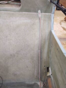
As the right GIB sub-panel layups cured, I then got to work on pulling peel ply and cleaning up the final layups on the GNS-480 GPS antenna cable. Apparently I forgot to grab pics or report on my GPS antenna cable progress, but here it is in its final state before the cockpit gets painted.
Again, with MGS epoxy it’s hard to tell, but there’s a ply of BID securing the GPS antenna cable from the bottom of the pilot seat back bulkhead to the top where the cable enters the seat back structure/rollover base.
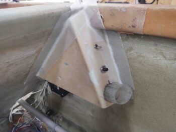
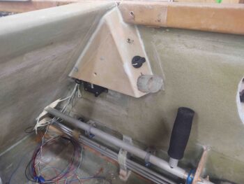
I then worked for a number of hours on the final configuration of the LEFT GIB sub-panel. I had to flatten the install angle of the USB charger to align it more parallel to AC centerline to get better clearance with the canopy latch rod. I also made up 4x 10-32 phenolic nutplate assemblies and mounted them on the underside of the sub-panel for the eyeball vent-securing screws. Again, I was in such a mad rush to get all this done that I failed to snap any pics.
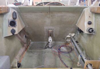
Before I got around to glassing in the LEFT GIB sub-panel, I pulled the peel ply and cleaned up the layups on the right GIB sub-panel. Here it is with the GIB removable control stick in the stowed position.
And a shot with the control stick nearly out of its stowage tube, to show that I made the diameter of the tube just a tad smaller than the diameter of the foam grip on the control stick so that the tube grips the control stick firmly.
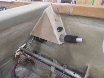
Although I removed the control stick assemblies in prep for paint, here I’ve mocked up the GIB control stick in place. I’ll note that I tested and double-checked the clearance between the control stick, and during use, with the aft lower edge of the right GIB sub-panel.
While I’d say I’m very happy with the right side GIB sub-panel, I’d say I’m somewhat happy with the left GIB sub-panel. I’ve already stated in practice I’m not a big fan of these side sub-panels, and if it weren’t so late in the game and I hadn’t set the position of the upper GIB air/heat vent via the main duct system, I’d have reworked this side sub-panel, especially after this last issue.
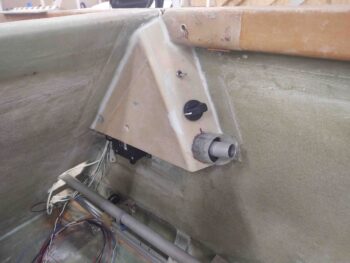
My mockups went well, but it’s hard to tell exactly how all will fit until the rubber meets the road when you do the final install. With the clearance, or lack thereof, with the components and especially the interconnect SCAT tube from duct to eyeball vent, to keep the inboard wall of sub-panel vertical and not angled inboard I had to come off the sidewall over 1/2″ (note the strip of green 0.063″ G10 that I 5-min glued, floxed and glassed in place). Again, this late in the game I was just not going to redo this panel and start over… my decision was to salvage what I had and press forward. And yes, it does translate into a little less knee room for the GIB.
My first issue was the angle of the sub-panel face is a good 5-10º too steep off the sidewall. I should have made it more perpendicular to the sidewall. By not having a shallower angle it made the components face too much outwards vs parallel to AC centerline. This had them pressing into the duct and minor clearance with the canopy latch rod. I expected to have to bring the sub-panel off the sidewall about 1/4″ max, but not over 1/2″.
[Note: during the layups the USB charger cap is not in place, but hanging down farther than normal. This makes it look like its both installed closer to the eyeball vent than it actually is, and also off-kilter in the last pic. Future pics will show this better.]
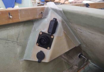
My blog post title, “function over form” alludes to the placement of the components in the sub-panel. I didn’t just throw these chargers and eyeball onto the face of the sub-panel willy-nilly, but rather had to configure them to avoid what lurks underneath: the alignment of the eyeball vent with the duct behind/underneath it, and the vertical & inboard placement of the USB charger to keep it from interfering with the canopy latch rod. A horizontal placement of the USB charger was out of the question, and if I tried to move it up any higher it would collide with the aft surface of the pilot seat back.
So it is what is, functional but not perfect. I’ll throw some lipstick on this pig by painting it and press on…
Ironically my buddy Dave Berenholtz recently commented on how nice I was being to the GIB by installing a bunch of this stuff, so I guess just to prove him wrong I extracted some knee room from them! (grin).
I may have missed my immediate window for painting the cockpit, but looking at the weather it’s supposed to be a nice day this coming Wednesday. The next couple of days are supposed to be rain, so unless the forecasts are wrong, Wednesday will be my new target day for painting.