
Today was pretty much all about electrical stuff, in prep to try to get the interior cockpit painted while the weather is good.
I started off creating a 16″ x 16″ plus sign out of copper foil tape for the ELT back plane. I started with one 16″ long strip of coper foil tape, and then added two 8″ pieces to it with a small gap in between them. I then simply added solder to all the edges and I got me an ELT backplane.
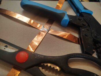
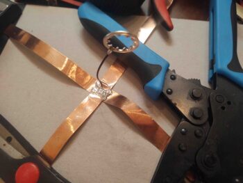
I then soldered the high-grip washer that came on the ELT antenna to a wire, and then soldered the wire to the copper foil strips. This will give me the required electrical continuity between the antenna mount and the backplane, as per the ACK E-04 manual.
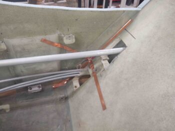
I then installed the ELT copper foil backplane into the right corner of the pilot seat. If you think the right angles for the backplane are incorrect, well, then you’d be incorrect… hehe. According to the owner and lead bubba at ACK, right angles like this are perfectly acceptable for a backplane. The big concern is actually having a backplane in a composite aircraft!
I then covered all the copper foil legs of the ELT backplane with a ply of BID. A fair bit of which I peel plied.
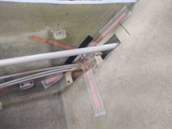
Jumping ahead a few hours, here’s the cured overlaid BID on the legs of ELT antenna backplane . . . yes, with MGS epoxy it’s hard to tell that there’s anything there.
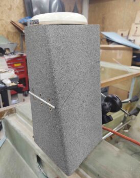
During the copper foil tape protective BID layup I added a couple plies of BID just below the crosspoint of the 4 backplane legs, and when it cured I floxed in the ELT antenna mounting bracket (in pic above too). Here it is a few hours later after the flox cured, with the antenna in place for a test fit. I think this dawg will hunt….

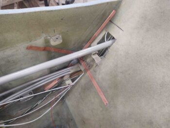
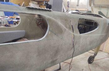
One of the many things I’ve pondered over the past few years was exactly how to run the GNS-480 GPS antenna cable from the panel mounted GPS to the pilot headrest-mounted GPS puck.
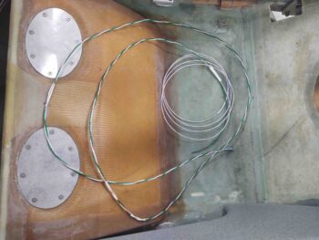
Here’s a shot of the GNS-480 GPS antenna cable when the pilot’s headrest is opened to access storage.
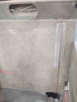
I finally decided that instead of punching through the back of the pilot’s seat at a low(er) point just to have the cable re-enter again towards the top, I would run the GPS antenna cable up the front face of the pilot seat bulkhead. I have it positioned so that it is right at the edge of the seat cushion. just barely covered by it.
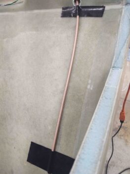
I don’t like making things inaccessible in case they need maintenance or repair, but I figured this cable is fairly low on the failure scale, so I simply glassed it to the front face of the pilot’s seat with a ply of BID. This is the first of a few piece of BID that will secure the GPS antenna cable to the front seat back.
I then got to work selecting some 16 AWG wire and building a cable for the GIB cigarette lighter style charger. I also printed off some labels and labeled the wires and the cable.
I then did the same thing with some 20 AWG wire for the GIB USB charger unit.
I then ran the wires from the USB and cigarette lighter chargers from the left GIB sub-panel over to the right side and out a hole I drilled in the pilot’s seat back just forward of the roll trim actuator pad.
I then grabbed the GIB right sub-panel and ran 2 sets of wires: The first went out the side wall to power/control the GIB map light. The second was the GIB lights power and ground wires that go forward to the TriParagon.
Also note that I 5-min glued the relay to the interior side of the right GIB sub-panel. I then had a small strip of 1-ply BID left over from the ELT antenna backplane layup, so I used it to help secure the relay to the inside surface of the sub-panel, just behind the switches.
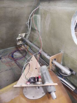
In addition to the the chargers on the left GIB sub-panel, I also routed the cables for the fuel site gages video cameras. The left side cable transits through the pilot seat back, while the right side comes straight in through the side wall.
BTW, I just today glassed in the clickbond that the adel clamp is mounted to.
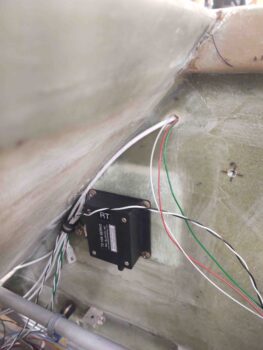
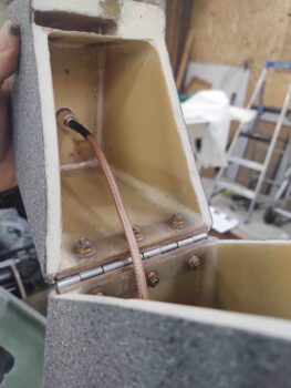
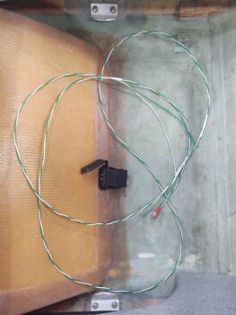
Here’s the left side fuel site gage video camera cable. This cable also includes the power leads for the fuel site gage LED.

Here’s the wires exiting the fuselage on the right side into what will be the interior wall of the strake baggage compartment. These wires are for the right fuel site gage video camera, the power wires for the fuel site gage LED, and the wires for the GIB map light.
My last task of the evening, as it was getting late, was to 5-minute glue the right GIB sub-panel into place. As you can I secured it in place (after holding it in place for quite a few minutes) with Gorilla duct tape.
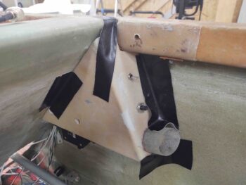
I then let the 5-minute glue cure overnight as I called it a day.