Chapter 22 – Last Panel Light

A few days ago I had 3 distinct electrical issues: the nose gear switch putting the nose gear down, the landing brake ancillary functions/notifications not aligning with the switch, and the top row indicator lights push-to-test button not working and popping fuses after every possible initial “fix.”

Well, as this build goes it’s taken a day each (along with other tasks) to get each issue resolved.  For the indicator lights, yesterday I had to disassemble a number of the connections both at the test power leads and the light power connectors in my attempt to test every circuit, which I originally believed was a simple miswiring of the circuitry.

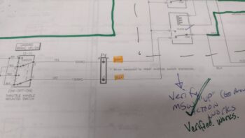
As I was doing my continuity tests I kept getting an errant connection to ground on all the test wires, which should all should only go to power BEFORE the PTT button switch was engaged.  It was clear: I had mole somewhere in the system.  But what wire and what circuit?

Again, as I noted yesterday, I discovered that in my haste to add the new AP SERVOS OFF/PCS indicator light I misread the type of output the Trio autopilot was using for this signal.  I took it at as positive power vs ground.  Ooops!  I had inadvertently wired in a ground wire to the bundle that was coming in through the light main power feed, and moreover had at some point blown out (destroyed) the protective diode that was there to protect the circuit feed (or it was dead when I installed it).  When I tested the installed diode on this circuit it was clearly inoperative.

Once I removed that bad connection, my first task was to correct that circuit to allow the depressed autopilot servo disconnect/pilot controlled steering (PCS activates with a greater than 5 second button push: allows the pilot to manually steer the plane for a bit, release the PCS which will then hand control back over to the autopilot) indicator light to illuminate.

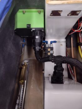
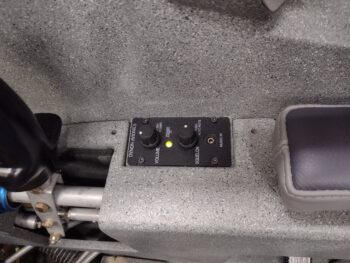
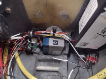
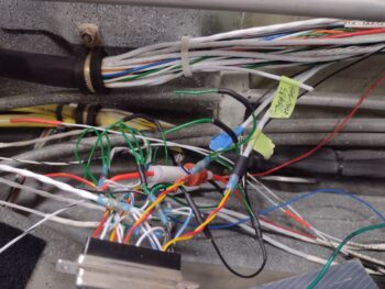
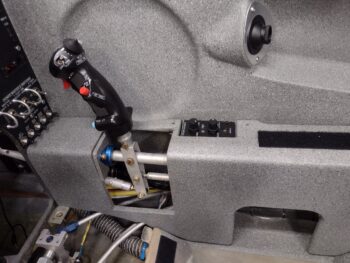
The issue with my original mis-ID’ing of this alarm output high vs low is that I now had a constant hot feed to contend with that goes through the control stick’s multiple ground outputs.  I had no way to isolate —without cracking the control stick open— exactly what ground circuit was on the other end of the wiring.  This forced me to control what I only had access to.  And other than simply abandoning this function and removing the light, this drove me to only one viable required solution for this control issue: a relay (yep!).

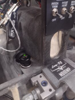
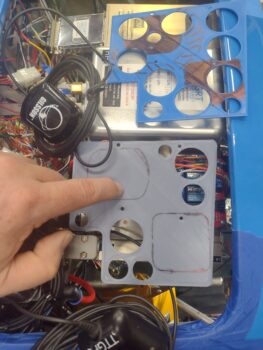
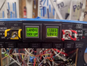
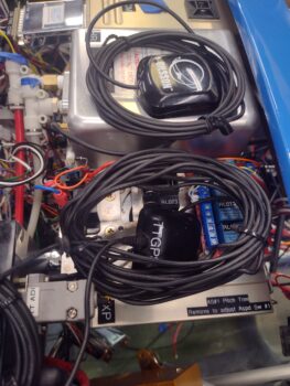
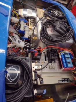
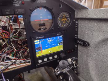
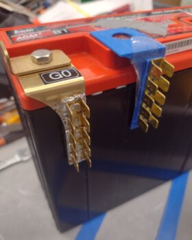
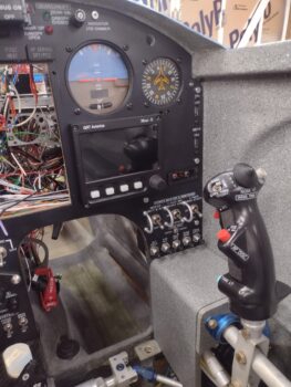
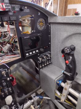
Which you can see down in the open corner of the HXr EFIS opening.  As you can also see that this relay allowed this circuit to work.

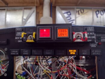
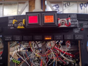
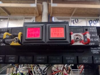
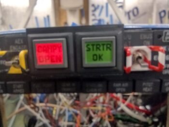
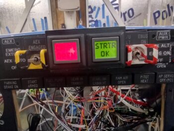
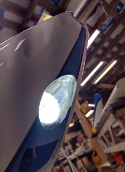
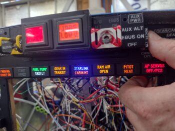
It also allowed me to reconnect all the indicator lights’ wiring and get those fired up as designed via pushing my Push-to-Test button on the side of the Warning Annunciator Sub-panel.

One unintended consequence, however, after I wired all these wires back up was that if I pushed the control stick AP servos disconnect button, all the indicator lights fired up… so it was either shorting out the entire light panel, or powering them collectively (sigh).

After messing around testing out another diode and even some high value resistors, in the end I simply punted and cut the test lead to the AP servo indicator light… meaning that it works as required when the control stick button is pushed, but from here on out it does NOT light up with the other lights when the PTT button is pushed.  Facts known, dealt with, and pressing forward.

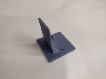
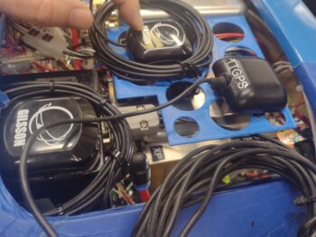
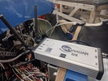
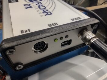
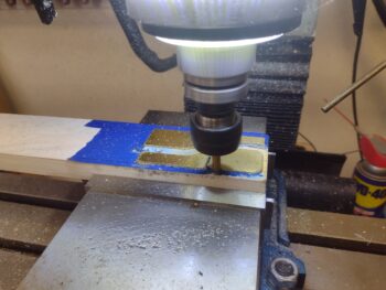
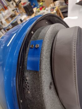
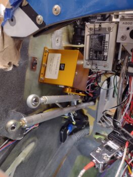
I’ll state that I did a good half hour worth of assessment on where exactly to mount my SkyRadar ADS-B IN receiver, now that I know that it must be aligned on all axes in relation to the aircraft centerline.  To attain this alignment, along with ease of power connection and my brand new requirement of remotely mounting the 2 antennas, I decided to test mount it on the inboard side of the Garmin GNS-480 mounting tube.  I further determined that only #6 110° CS aircraft grade screws provide internal clearance for securing anything to the mounting tube, so I started some initial test component designs in CAD and kicked off some 3D prints on those bits…. after I tweaked and 3D printed the latest version of the right side GPS puck mounting plate to test out before making.

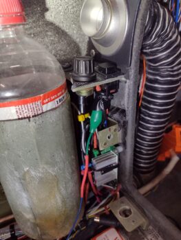
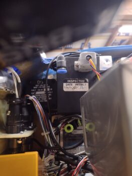
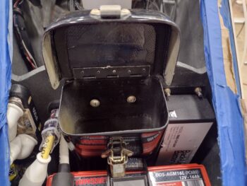
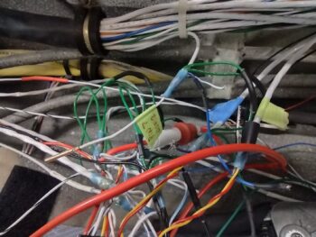
I then spent a good 45 minutes installing and securing the hardware on the quite difficult to access P3 connector (kinda visible upper left corner of pic behind wires).  Another insane-to-get-to job complete.

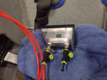
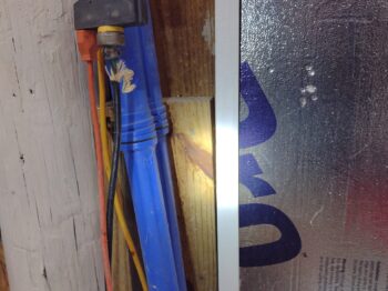
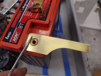
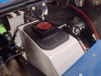
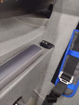
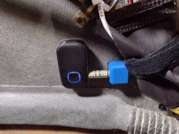
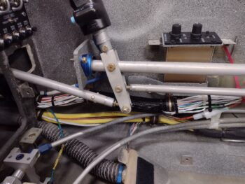
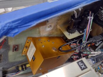
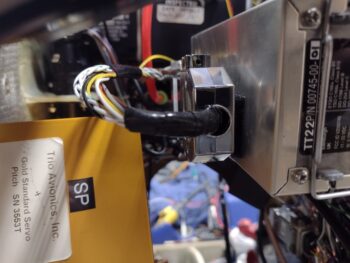
I then added some strips of Velcro onto the inboard side of the Trig TT22 transponder GRT serial adapter and backshell to attach it to the transponder itself.  Here is the adapter with the interconnecting wire pigtail I made yesterday, shown from the front side looking aft.

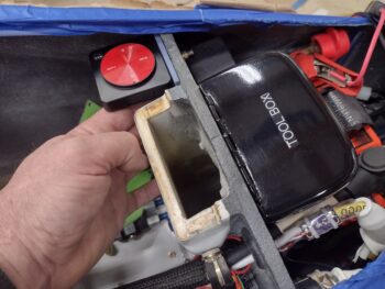
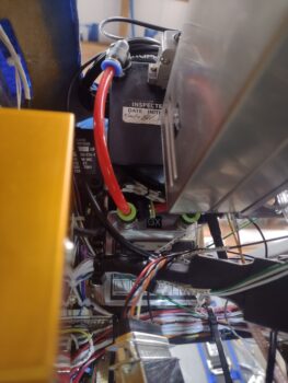
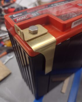
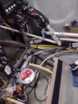
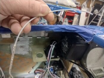
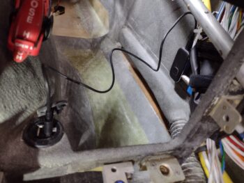
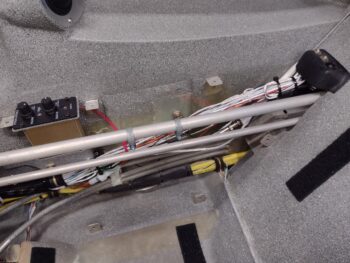
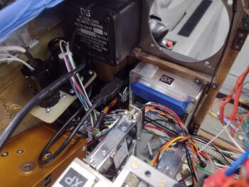
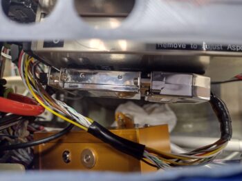
And a shot looking down at the transponder serial adapter/wiring pigtail install. I need to pick up some 1/4″ 4-40 screws to finish attaching the D-Sub connectors, which I’ll do tomorrow. After the D-Subs are fully secured, I’ll then zip tie the wiring and the adapter to the transponder which will complete the install for not only the serial adapter and pigtail, but the transponder itself.

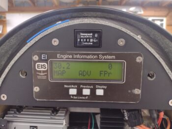
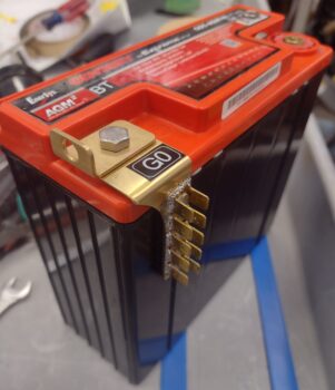
As for component power up tests, I’m happy to report that both the roll trim and pitch trim systems and actuators all powered up nicely and are working a treat.

Pushing forward!

Chapter 22 – Panel LEDs fixed…

I started off today having a leisurely morning with Jess, as she was busy in the kitchen I focused on some arts n’ crafts time by building a 10″ long pigtail with 25-DSub connectors on each end.  One end of the pigtail connects to the Trig TT22 transponder while the other connects to the GRT adapter that allows the HXr EFIS to remotely control the Trig TT22.  The other side of the adapter will plug into a D-Sub connector that goes to the HXr.

Now the question: Why?  Because I originally planned to have the Trig TT22 mounted on the TOP shelf of the Tri-Paragon —OR— out in the end of the right strake.  But after deciding to mount my ELT antenna in the nose I found that after making up a bracket the transponder fit hanging off the right side of the Tri-Paragon’s top shelf… sort of.  To be clear, there was no clearance for it to fit on the shelf top.

All but for that GRT serial adapter.   With the TruTrak ADI installed there is simply no room for the adapter.  I figured we’re talking electrical signals here, so a quick call to GRT to let them know my eevil plan to remotely mount their serial adapter… that ironically let’s one remotely mount the transponder.  They saw no issue with my scheme.

I did a bit of research last night, but did a deeper dive today on Radenna SkyRadar ADSB-in receiver install per the manual.  As noted above with the Trig transponder, figuring out where to mount components has significant consequences to not only that respective unit, but can have 2nd, 3rd and 4th order affects on other stuff as well.

Since I originally planned on the transponder antenna being in the outboard right strake vs the nose, all was good with mounting the SkyRadar receiver either on top of the NG-30 cover (original plan) or on top of the canard.  However, with a quick check in the SkyRadar manual it states that it’s an absolute no-go to have the 978 MHz or 1090 MHz antennas mounted within 4 feet of the ELT antenna.  Ugh. (BTW, 4′ away is the bottom aft edge of the pilot thigh support where it meets the flat pilot seat “pan”).

The only saving grace is that the SkyRadar antennas can be popped off and remotely mounted, and they’re not that big (~6″ long per antenna)… only requiring buying or making the cables required to remotely mount them (again, a common practice with the RV bubbas).

So [once again] a minor install task has morphed into a significantly more involved project.

In other news, I found the culprit preventing my panel indicator lights Push-to-Test switch from popping fuses.  Again, my bad in not fully reading the wiring diagram correctly as I hamfistedly installed the new AP SERVOS OFF/PCS indicator light. A fact I quickly discovered after doing connectivity tests on my PTT wiring circuits.

A correct rewiring of the AP SERVO indicator light should have it back in the mix in short order.

I spent a few hours taking it easy after my late afternoon fun-with-wiring activities above since I had a killer headache… a rare malady for me.

But the shop lights were still on as I kept telling myself I would get back out there to knock out more stuff… which ended up just me fusing the RAM air scoop butterfly valve switch/actuator circuit.  The only panel indication that all these components are functioning as designed is the RAM AIR OPEN indicator, and yes, both switch and actuator worked a treat.

Nice… another power-up test on another component circuit tested good.

And with that, I called it an earlier night than usual.  I plan on being back on the build hot n heavy tomorrow.

Chapter 22 – Nose Gear fixed!

Again, before I dove into troubleshooting the nose gear not-going-down issue, I wanted to knock out some low hanging fruit.

My first task was fusing the TCW Tech SmartStart unit before pressing a couple of buttons <secret?> to arm the starter for engine start.  Obviously this arming step, and ensuring the indicator light lit up, were the only test on this system at this point.

I also fused the StarLink/Cabin heat relay circuit (StarLink may get swapped for WXWorx Satellite WX depending on StarLink’s pricing and plans available) to test out the circuits.  Upon flipping the StarLink switch on, the circuit looks good (a bit more on this below)….

I then got to work on the nose gear down issue.

I checked the 2 suspect wires on the external P0 connector and they both were secure and looked good.  But sure enough when I cracked open the Relay Control Unit (RCU) I saw the brown wire socket looking like it wasn’t in the socket hole deep enough… and I was right.

The wire just pulled out of the RCU-side P0 connector socket hole when I checked to see if it was secure.  I’m guessing iterations of disconnecting the connector and reconnecting it challenged a weak-seated socket.  I flared the little catch tabs on the side of the socket out a bit and then inserted it back into the socket hole… which was a bit challenging given the space to do it.

And Voila!  The nose gear functioned perfectly up and down with this socket back in the game.

I then put everything back together, put some flexible conduit over the wire cabling, and then did another test of the nose gear system to ensure it was working.  All still good!

I’m going to put a quick plug in here for both my wiring diagrams and the connector pin-out diagrams (below) that made this nose gear troubleshooting much easier.  Although not perfect, I’m glad I took the time over these past years to keep them mostly updated!

Now, when I fused the StarLink/Cabin Heat power relay system, the CABIN HT light was not illuminating when I flipped off the StarLink switch.  Although StarLink has priority and will cut off power to the cabin heating system, with the StarLink switch off the CABIN HT light should come on when the Oil Heat System is turned on.  But it wasn’t (clearly this pic was after I fixed it…)

I’m not overly surprised, as the access to the wiring for the heating system (both oil heat and seat warmers) is virtually non-existent.  The wire I could get access to (barely) was one that I hoped would power this light, but upon closer inspection it wasn’t the right one.  Moreover, if I tie into the power wire than the CABIN HT light will simply stay on all the time… a bit silly in my book.

So to get the Oil Heat side of the system to power the light, after multiple crazy attempts over 15 frustrating minutes, I punted and decided to join the ranks of hacks and cheaters.  And although I’m not proud, I am happy this task is complete.

I’ll start by noting that this is not a safety-of-flight indicator, just a “nice to know” one.  So I used the end of the same alligator clip I used to find the good terminal off the switch, cut it and spliced it to the blue 22 AWG light wire, wrapped the clip with electrical tape and then zip-tied it to secure it.  Janky! But task complete.

I also did a function and fit test of the original design prototype for my Dual GPS puck mounting bracket that I designed up in CAD.  After the initial check, I tweaked the dimensions a good bit before 3D printing this one out in ABS for actual install.

How does it work you ask?  Well, I just discovered after all these years that the bottom plate of the Dual GPS puck has a slot to allow attaching it to a band.  The thickness of the slot is 0.09″.  The tab on this mount is the same thickness, so the puck firmly slides onto the tab to securely mount it into place.

And this is where I plan to put it, so I can simply pop the nose hatch to turn it on & off.

The one downside is that the screw holes that I need to drill to secure it to the aft side of the Napster bulkhead are lower than the IBBS unit on the front side… so that will have to come off for a bit after I remove the battery again to complete this install.

My priority tomorrow will to get the panel indicator lights Push-to-Test function online and to stop popping fuses!  Then I’ll get back to work getting these panel components and circuits tested out so I can finish up installing the remaining avionics in the panel!

Chapter 22 – Fixing stuff

I started off today knocking out a few more power-up circuit tests with the target being the USB and cigarette lighter chargers for both the front pilot seat and the GIB.  Here we have the pilot cigarette lighter charger just forward of the lower instrument panel bulkhead and just to the left of the center panel strut (pic 1).  If you look closely, you can see the green light.  I’ll also point out that this charger is on the battery bus so it’s always hot.

In the back seat area, left upper side just aft of the pilot seat and just below the longeron is the pair of chargers, both USB and cigarette lighter style (pic 2).  Again, looking at the lights you can see these are both powered up.  Moreover, with each charger I plugged in my phone to ensure that it was charging, which it did on all the chargers.  These chargers connect to the Master Bus off of one fuse.

Lastly is the pilot USB charger located on the right side of the panel’s center strut.  It has its own fuse off the Master Bus.  Here I have it charging the Intercom Bluetooth module anytime the Master Switch is flipped on.  Interestingly, there are no lights on this unit to let you know that it has power, other than charging something.

A couple of days ago I started converting the Tri-Paragon relay deck CAD model to use its screw hole patterns to create another deck one level above the relays: a GPS puck mounting plate… I have GPS pucks coming out of my ears and I think they just may be multiplying like rabbits!

In the lower left corner is the Mini-X GPS puck mounted atop the TruTrak ADI.  Yes, it’s easier cable-wise to get it sitting nicely on the ADI moreso than the ADI’s own GPS puck, which is the farthest forward (to the right) in this pic.  The GPS puck at the top is the GRT AHRS, with the puck itself situated close to the inboard edge of the shelf plate with only the wrapped cable overlapping onto the AHRS (I confirmed with GRT that this is ok).

Well, after getting the puck locations dialed in, I then removed some of the lightening holes to give both antenna pucks a solid surface to sit on.  i also rounded the corners before 3D printing Version 2.

This morning I picked up some 2″ long CS brass screws and used them —after cutting some aluminum tubing for standoffs— to temporarily install the Version 2 GPS puck mounting plate.  The ADI GPS puck wire bundle will get zip-ties to the outboard edge of the plate and hang down vertically below it.

Of course I have some tweaks that I’ll make over the next few days before I spit out Version 3, and then when the final version looks good I’ll cut it out of 0.035″ thick 6061 aluminum.  I’ll also note that I have 2″ long CS 4-40 screws on order from McMaster-Carr and will add in 2 more support standoffs towards the front of the plate.

BTW, if you think this plate is the end of the story for GPS antennas, think again…ha! I have another GPS puck for the MiniUni2 back-up EFIS/timer and another one for the SkyRadar ADS-B IN receiver, over on the left side of the avionics bay.  And I’ll go ahead and mention my standalone Dual Bluetooth GPS puck for my iPad.  I think I have a spot picked out for that as well.

Lastly, I’ll note that per the Garmin GNS-480 installation manual, NONE of these GPS pucks will be mounted on the aircraft centerline as that honor is the GNS-480’s GPS puck’s alone.  In fact, none of the GPS pucks are on the same plane in relationship to each other (close, but not directly) front-to-aft in the bird.

For more than a week now I have been designing and printing out a sleeve that in effect clamps the Fuel Fume Detector onto the AFT side of what was supposed to be its “panel” mount.  However, due to the very short throw on the nose hatch door cable handle release (<1/4″) I felt I should have a positive block to keep from inadvertently ‘popping the hood’ inflight.  That latch handle block intrudes into the space for mounting the fume detector in a normal instrument install fashion.

Now, that all being said, after the 4th iteration of this sleeve, and it fitting very well (there is nothing else holding the instrument in place at this point in this pic), I figured I should wire it up and test it out before I glue this sucker into place.  The control head (in the pic) tests out fine, but there is a bit more detailed test to do with the sensor, which is back by the GIB seat bulkhead.  Once (and if) that is good, I’ll install this unit with RTV.

I guess I should remind ya’ll that the fuel vapor sniffer above is meant to be just a temporary install to ensure that there is no fuel vapor in the cabin during the first 3-6 weeks of actual flight operations.  After it proves no fuel vapors present my plan is to remove it.  I picked this idea up from the VANs bubbas on the VAF forum.  However, if I need to plunk down any more serious cash for a new sensor, I very well might just punt and scrap the whole idea.

I also wanted to quickly show you what I see currently when I fire up the Master Switch on this bird.  I already mentioned the red CANOPY OPEN alarm on the left AG6.  Well, after a few days use with no actual recharging going on, I now am getting an amber IBBS LOW V[olts] alarm on the right AG6.  I guess these are letting me know they’re working eh?

Now, how about that Landing Brake?

Many moons ago when I first posted my switch configuration on the throttle handle, I got a call in short order from my buddy Marco, an airline pilot.  He chewed me out, called me stupid and said I needed to get my sh*t together regarding my switches!! (ok, I might be embellishing a bit… haha!).

In all seriousness, he mentioned the aviation standard, at least in the airlines, is during a go-around that all levers and switches go forward, and I had my Landing Brake switch with forward DOWN and aft UP.  You learn something every day, huh?  And looking at the diagram, which is a near exact copy of Jack Wilhelmson’s diagram, I simply reversed the leads to the switch to meet this newly learned standard (pic 1).

Now, I have recently dealt with how confusing this diagram is (to me anyway) and even had to recently rewire something that I misinterpreted since the diagram is not easily transposed into the physicality of its wiring in my bird.  And as my wife was making dinner tonight, I had an aha moment and realized exactly what was going on:
⇒ I had swapped the wires UPSTREAM of the switch and relays vs DOWNSTREAM where it simply swapped up vs down per switch input.  I needed to set those leads back to what they were, and swap the actual power/ground (which flip-flop depending on switch position) wires to the actuator itself (pic 2).

After getting into the P4 connector and swapping the wires back as per my original diagram, my point of swapping the Landing Brake power leads was under the pilot thigh support just aft of the ELT (which I obviously dislodged temporarily for this task).

Voila, it worked!  The Landing Brake operated per throttle handle switch labeling, with down kicking off the amber LANDG BRK DN AG6 alert (pic 1), and then when I flip the switch to up I get the green LANDG BRK UP notification (pic 2… not sure on the green IBBS Low V on the right. Probably need to tweak that alarm input parameters).  Moreover, full throttle resulted in the Landing Brake automatically closing.

Task complete.

Now, I failed to get a shot of this yesterday, which is simply a single light for GEAR IN TRANSIT when the gear is going either up or down… that replaced the 2 separate gear up/gear down lights.  Still, it is notifying me so I’m calling it good!

I then spent well over 2 hours tracing and performing continuity checks, taking voltage readings, etc. on the nose gear down no-go issue.  After all that work, I finally narrowed the culprit down to 2 possible wires in the P0 connector OR a single relay post connection inside the RCU.  That being said, as I was checking continuity and failed to get any tone, when I re-positioned the lead and bumped the wire bundle I got tone.  I then quickly connected it all up and got the gear to travel down for about 5 seconds.  That told me I have a contact issue in either of the two wires I targeted.

Since it was very late, and I spent way more time than I expected on my troubleshooting, I called it a night and headed into the house.  I’m very confident that I’ll figure out the gear down issue tomorrow and get ‘er fixed.

Fighting on!

Chapter 22 – Testing stuff out

I started off today testing another component in my IBBS-powered suite of stuff: the Radenna SkyRadar ADS-B IN receiver, that I plan on mounting on the top centerline of the canard (pic 1).  As you can see, the green power light shows that it is getting juice (pic 2).  Initial power-up test good.

I also received more 1/4″ tubing push-to-connect fittings today which allowed me to finish configuring the Mini-X EFIS for its pitot & static connections.  The incoming pitot & static feeds from the GRT AHRS will connect to the center/sides of the “T” connectors, while the open (forward) end of the pitot “T” connector connects to the TruTrak ADI.  The ADI requires no static feed, so the end of the static “T” connector is plugged for future use.

I then did the final official install of the Mini-X, 4 screws and all, and connected up the ADI’s pitot input (pic 1) as well as Mini-X’s pitot & static feeds to/from the AHRS (pic 2) [note the GPS pucks cable loops and initial positioning of those… assessing mounting]

And here is my updated pitot/static diagram… besides the right side static port connection, the right side of the panel is complete.  I’ll note that my configuration is a bit like a triangle, with the right side pretty much done, the left side (base) still needs plumbing, as does the forward (top) side with the 5 airspeed switches (AEX has 2) in and around the F22 and F28 bulkheads.

I’ll further note (if you read my annotations on the diagram) that I’m following Joe Gore’s lead (he’s helped me considerably on electrical stuff via the Aeroelectric Connection forum) in NOT plumbing the Airspeed Switches’ static ports since a good number of them have a tendency to leak (remember, Jack Wilhelmson didn’t utilize the static port on his original AEX unit).  Thus, I’m “going ugly early” on this implementation.

In the nose I terminated all but a few ground wires onto the G0 Ground Bus.  The 3 ground wires that I didn’t finish yet is because I want to ensure/confirm their length and routing around the battery to allow me to secure them in a nice tidy bundle along with the other ground wires.  That will come the next time I remove the battery.  In addition, I purchased some hardware for the battery post connections that I’ll add into the mix the next battery removal/install.

I threw a fuse into the Battery Bus fuse panel to allow me to test the circuitry on the Landing Brake.  Now, although it lowered and retracted as per the labels on my throttle handle switch, the AG6 annunciation was backwards and the WOT=Landing Brake retraction feature didn’t work… after some thought I’m pretty sure I know exactly what’s going on with that and will fix it tomorrow.

Not shown is the nose gear test.  I have an issue there too with the gear retracting up fine, but the when I flip the switch for the gear to deploy (down) it’s currently dead… a no-go.  I have zero thoughts on what is causing this issue, but the one positive and unexpected discovery that I made out of this is that tiny little nose gear back-up battery is not only strong enough to put the gear down, but that little sucker can lift the entire nose off the ground (and that’s without the counter-balancing engine installed).  Impressive!

Yet another small but notable discovery I made was when I powered up the bird with the Master Switch.  I initially thought I might have an issue with the pair of AG6 Warning Annunciators since they were colorless.

It turns out (duh!) that when they are connected to the dimmer, and the dimmer is turned off, then it stands to reason they have no color (good to know… I’ll assess further).

You may not be able to tell in the pics, but pic 1 is with the dimmer as low as it will go with the dimmer on.  Pic 2 is with the dimmer turned all the way bright (again, the red looks washed out on camera, but the lettering is actually a very visible black).

Issue #3 deals with the top row indicator lights, where I ran through a few different blown fuses before I realized there is an issue with the Indicator Push-to-Test circuit where it’s shorting out somehow.  Another troubleshooting task on my list to work tomorrow.

That being said, one of my parameter checks was to avoid using the PTT button to see if individual component indicators were working.  Here I tested the parking brake  handle indicator light, which clearly is working.  That again points more to the PTT circuit as being the antagonist.

It also probably goes without saying, but note that in every shot of the panel the left AG6 screen is constantly red with a “CANOPY OPEN” warning.  This starts off flashing until I push to acknowledge that yes, the canopy is open.  The red canopy warning will continue to flash (if I don’t acknowledge) and permanently stays red until the canopy is closed and the handle locking lever flipped back.

Finally, as you can see here I’m clearly working my way from the right side of the panel with the avionics mounted on that side.  I’m working through powering up and testing every component I am able to (e.g. landing brake, nose gear, indicator lights) to work through every electrical and configuration issue while I still have free and open access to the wiring to troubleshoot what I need to.

Pressing forward!

Chapter 13/22 – Pitot-static start

Starting off, here is a pic of the pitot-static “T” fittings on the GRT AHARS (middle of pic) and the 90° right angle fitting on the TruTrak ADI (bottom center) that I installed yesterday.

Again, here is the 90° fitting on the TruTrak ADI.  My first task today was installing the one straight fitting I have on hand into the pitot port on the MIni-X, immediately followed by a “T” fitting that will connect to the ADI on the forward-facing side, and to the AHRS on the inboard facing side (pic 1).  All this after testing out other physical configurations.

Meanwhile, over on the left side I connected a 3-outlet manifold to the Alt-static valve (switch) that sits on the panel (pic 2).

After testing out a few different physical configurations, I finally settled on the double-fitting setup on the Mini-X to connect it from the pitot and static lines coming from the AHRS and then connecting those via the “T” fittings to terminate at the TruTrak ADI (pitot only).

Through my testing shenanigans and pitot-static machinations I literally updated my pitot-static diagram significantly 3 times by mid-day today.  Although not a beauty of a diagram, it works for what I need to document my pitot-static plan.  Again, I have parts on order to allow me to finish installing the pitot-static system fairly soon.

Back on the electrical system, I re-installed the glass 3-amp fuse into the IBBS power feed for the GRT EIS.  I then flipped on the IBBS power switch to see if the EIS was getting power, and as you can see it fired up.   Initial test complete.

The only other components connected to the X-Bus/IBBS is the GRT HXr and AHRS, and since the HXr is not installed I’m not testing that circuit yet.

So I tested out some components powered by the Master Bus, starting off with the Dynon Intercom… with only the green LED being the only indicator of power at this point, but that is clearly a great starting point.

I also installed a fuse into the Wig-Wag/Landing light position on the Master Bus and tested the 2-position switch with the middle position firing up the wig-wag and the top position powering a solid light beam.  Test good (I’ll test the wing wig-wag/landing lights controlled by the same switch when they are installed).

Here’s what that looks like on the actual bird.  Please ignore the dust inside the landing light lens, I’ll get around to cleaning that at some point!

My last test was on one of my 2 dimmers, this one controls the panel lights.  This dimmer also controls dimming the AG6 Warning Annunciators and the Trio autopilot (not yet installed), which will get tested when I’m ready to fire those up.   I turned the shop lights off so you can see the max lighting on the TruTrak ADI and the Vertical Card Compass. Another successful test.

What is not successful are 2 issues with the Mini-X.  The first being my OAT value is not showing on the screen, although the probe wires are physically connected to the Mini-X connector and ground.  Issue #2 is that when I flip the Master Switch on I almost immediately get a Low Bus Voltage warning message.  Thus, when I pull the Mini-X to install the Static fittings, I’ll be doing some circuit testing to check these things out.

I also have a couple of development projects going that are in their initial stages: one for a mounting ring to allow me to install the fuel vapor warning sensor (for the first few months of flight ops to ensure no fuel leaks in the cockpit) and the other for a GPS puck plate that I will test installing on the right side of the avionics bay top opening.  As those get further along and are viable I’ll post pics and discuss.

My last official act of the evening was to widen the lower mounting holes on the bottom back side of the nose tool box that allows it to slide down onto the reverse mounted Clickbonds.  With the battery strap slightly pressing against the tool box it made it a bit harder to get the bottom holes aligned with those bottom securing nubs, so widening them just a tad did the trick.  Toolbox installed! (until the battery gets removed again…)

Pressing forward!

Chapter 22 – Power up!

Another day full of research, reading, assessment and multiple pitot/static plumbing system reorganizing based on paper design vs the physical space in the bird.  I picked up a length of high-end 1/4″ fuel hose to use in the nose to connect the pitot tube to the sidewall pitot tubing… initial tests were good as it didn’t collapse, but still more fine-tuning required.

And although not pictured, I installed “T” fittings on the GRT AHRS box and swapped out a straight fitting on the TruTrak ADI pitot port for a 90° right angle fitting.

I then got busy cutting, trimming and crimping the terminal connectors onto the  battery cables.  Sorry, no intermittent step pics on those since I was in get ‘er done mode since this whole process is taking way longer than I planned for.

All told the ground cable (right side of battery) that is only visible through its attaching bolt, the left side positive cable on the front side of the battery and the Tri-Paragon ground cable (top battery, right side) were all completed (note the blue fuel-line tubing being tested/configured for the pitot tube).

I still need to terminate the G0 ground bus’s respective nose component ground wires… and clearly for a visual I threw in the Tool Box for a good look at how this area will appear during normal ops; just a bit more tidy.  Note the left-side (upper right side of pic) located TCW Technologies Integrated Backup Battery System (IBBS), which will be the subject of my panel components test below.

With the battery in place and cables firmly attached (I will need a more specific bolt, washers, etc. that I plan to acquire tomorrow), I then tested the IBBS back-up battery function by flipping on the IBBS switch (located lower center strut, pic below).  This switch flip should have resulted in the GRT Mini-X EFIS, the TruTrak ADI, and the MiniUni2 mini backup EFIS all powering up… as you can see, unfortunately, the ADI did not power up.

But the Mini-X did nicely…

As did the MiniUni2.

Again, here, these are powered via the TCW Tech IBBS (in the nose), NOT the Master Switch (yellow pointer) which remained off during these power-up tests.

As a reminder, the IBBS power switch is the bottom right switch on the center strut of the panel.  I forgot to grab a pic, so I reused this one.

Clearly I had an issue with the TruTrak ADI not powering up, but after a good 30 minutes of troubleshooting I fount the culprit: the ADI power wire FastOn at the X-Bus fuse panel.  After a lopped off the bad FastOn and crimped a new one on, Viola… issue fixed.

Which resulted in my initial test goal: all 3 panel units powered up via the IBBS powered X-Bus.

Today’s mission complete!

Tomorrow I’ll add the GRT Engine Information System (EIS) unit to the IBBS power-up test list, and then get back to finishing up the electrical system install.

Chapter 22 – Nose Ground Bus

Another 2-day update here.  Wow, time flies when you’re building an airplane!

Lots of research and purchase orders going in to figure out and acquire all components for the pitot/static plumbing.  That’s taken up a good few hours each of the last couple of days.

I also got around to knocking out one of two remaining (that I’m aware of) machining jobs I have on the books: the brass G0 Ground Bus that hangs off the battery’s negative post in the nose (job #2 is the right angle bracket for the GNS-480 mounting tube).

I started by cutting a brass plate to length and prepping it for milling.

I then proceeded to mill the brass plate (pic 1), which thankfully didn’t take too long… here’s the end result of the G0 Ground Bus tab that will get mounted directly to the battery (yep… cheating!).

After cleaning it up and deburring the edges, I checked the hole fit around the raised center brass ring on the negative battery post (pic 1).  It fit near perfect.  I then secured the battery cable attach bracket into place (pic 2).  Note how dirty the L-bracket is… destined for a white vinegar bath in the morning.

Day 2 morning: I carefully bent the G0 Ground Bus tab over in the vise and then remounted it onto the battery (note the CLEAN L-bracket!).

I then secured the double-row FastOn connector tabs first with a rivet, and then by soldering around the perimeter and in the center rivet holes.  I had used my left over vinegar and 3M Scotchbrite pad to clean the mating surfaces, but for some reason my solder was being finicky about wetting out and flowing between the components.  That being said I couldn’t pry the tabs off with my bare hands after soldering, so they’re on there pretty darn good (I had expected some possible shenanigans with the solder, thus the rivet!).

Note the 3D printed mock-up that I tested out a month or so back when I designed this G0 ground tab in CAD.

And here we have the final pic before it gets installed into the nose… which is coming up within the next day or two.

In prep for the battery going in, I did a good bit of work on the heated pitot tube… primarily assessing how to plumb it up to the sidewall pitot tubing.

I also terminated FastOn connectors to the white (power) and green (ground) wires that connect the small back-up battery to the nose Auto Gear Extension system (pic 1).  After installing the angled bracket battery securing tab, I then also wrangled a good bit of the local wires into the right side Adel clamp.  After I wire up the Taxi Light actuator relay coming up soon (lower right corner), I’ll install the left side Adel clamp (pic 2).

And with that, I’m calling it a night.  Much more to do in the nose tomorrow.

Chapter 22 – TruTrak ADI installed

Although I got a good bit of stuff knocked out today, I spent a good portion of the morning reacquainting myself with terminating coax cable connectors and installing the pitot/static system.  As Abraham Lincoln reportedly said: if he had 7 hours to chop down a tree, he would spend 6 hours sharpening his axe.  Thus, my day started out with some mental “axe-sharpening.”

Let’s start off with the low hanging fruit… a question I’ve had for a while was where to put the Dual BlueTooth GPS puck that my iPad requires for GPS when using my FlyQ EFB app. I decided to simply slap it on top of the NG30 cover: making the turning on and off of it a simple opening of the nose hatch and pushing the on/off button, then closing the hatch.  EZ-PZ.  Task complete.

In addition, I stopped by the Aviation Parts Store (True Value Hardware) to pick up a 1/4-amp glass fuse for the GIB Bose LEMO jack’s power feed that ties into the Dynon Intercom’s power wire.  Both pilot and GIB Bose LEMO jacks tie to the main power wire via inline fuses.

So I installed the fuse and then finalized wrangling all the added Intercom wires, which including swapping out the Adel clamp for a larger size, midpoint between the intercom unit and the pilot headset/headphone jack block (as I did with the Adel clamp between the control stick and panel yesterday).  I then secured the bundle of wires as can be seen with the black zip ties.

Although not very easy to see, I also terminated and routed the ELT antenna cable onto the antenna base (midway vertically between seatbelt clasp and aft armrest mounting tab).

Speaking of seatbelt, clearly it’s visible in the pic above as it is now installed.

The reason for all these final right side pilot seat area tasks is that once I trim the aft upper edge of the armrest and it fits in place, the armrest will be screwed into place with no immediate plan to remove it.

Here’s another shot of the ELT antenna cable routed and secured under the pilot thigh support, where it terminates into the ELT on the left side.

After a few iterations of notching, trimming, and sanding the aft top edge of the right pilot armrest to fit around the pilot headset/headphone jack block, I then installed and secured the armrest with a couple screws on the aft end… out of the half dozen screws that will get installed later.

Here’s a closer shot of the pilot’s aft right armrest with the headphone & headset jack block mounted in place.

Back to my “axe-sharpening,” where I found my PowerPoint notes regarding the pitot/static system, with pertinent links to VAF forum posts from Paul Dye’s system that he redid under the guidance and tutelage of Stein.  Part of my evaluation was to go ahead and install the TruTrak ADI on the upper right side of the panel . . . and

part of that install was to assess the placement and real estate required for both the Mini-X and ADI respective GPS pucks, that always come with the requisite bundle of wires that MUST NOT BE TRIMMED to a workable length… the ultimate prank that instrument manufacturers play on us peasants!

Pitot/static tube line and GPS puck placement assessments aside, the more pressing reason for installing the ADI at this point was to ensure clearance between it and the Trig transponder unit, given that when I designed the panel I FAILED to take into account the length/depth of the Trig transponder’s D-Sub adapter that allows it to be controlled via the HXr EFIS.

My Frankenstein plan is to create a D-Sub pigtail between the adapter and the Trig transponder to provide the clearance required between these two components.  I’ll be calling GRT tomorrow to grovel for authorization to engage in such heretical shenanigans.

And with that folks… pressing forward!

Chapter 22 – Intercom installed

Alright sports fans, a busy past few days… including a number of social engagements that knocked me a bit off my schedule.  But I did get a good bit done.

I mentioned my chicken-scratched diagram to keep me organized on my wiring reconnects on the Dynon Intercom.  However, toward the final wiring steps I found a wire that was not fitting into the matrix (green tape ID’d for pin 7).  It was clearly part of the previous Intercom wiring (split for years between with wires coming from the front, from the GIB/aft and those on the panel mock-up), with ground pigtails coming off the shielding and a D-Sub socket crimped on the end of it.  Clearly it was destined for the Intercom… I mean, what else in this specific area would it would be for?

Well, first off, I had misread the small numbers on the face of Intercom wiring harness D-Sub connector and thought socket 7 position was open, but it wasn’t after a second look.  I then accounted for every wire in the D-Sub connector, and determined I had NO open spots for a single wire.  I guess I should point out that my mystery wire had no visible labels since it was encapsulated in the wire bundle.

I then connected Relay #9 to power to test it out and allow me to do a continuity check on the wires connected through it to both the COM1 (Garmin GNS-480) and COM2 (Trig TY-91) radios.  I also toned out all the headphone, mic jacks and PTT wiring both front and back seats.  These checks included all the shield grounds.  All wires checked out and all socket connections were accounted for… the deduction in my investigation was clear: I had an extra wire in the mix!

Begrudgingly, I removed zip-ties and pulled the big bundle of wires apart enough for me to find a buried wire in the mix that was labeled for “TCM001″ (pic 1).  CM is the electrical component ID for the COM2 radio and 001 is the pin number.  Just one big problem with this label: my COM2 radio has no required wire pinned on its connector at pin 1.  I again deduced that this wire was yet another holdover from when I had wired up the panel for the Microair M760-REM remote radio, which I had planned on using for my COM2 radio but was forced to change my plans after they stopped selling them.

I decided that instead of pulling the wire out of the bundle to simply remove the labels and ID it as a spare wire (pic 2).  Mystery solved and I pressed forward.

In related news . . .

After some research I pulled the trigger on a BlueTooth module that connects via a 3.5mm jack to the 3.5mm socket assembly that I wired up to the Dynon Intercom.  Here you can see both of those modules installed on the lower right sidewall, just forward of the right pilot armrest.

It took a little bit to figure out where I was going to mount these guys, as I originally had planned on all this being in the GIB area on the sidewall.  I then figured if I was flying alone and wanted to use this Intercom function, I clearly couldn’t reach in the back seat to turn it on.  Plus, the angle of the pilot’s seatback would make both installation and control manipulation a bigger pain than if I just ran it forward… EZ-PZ.

Finally, here is the recharge cord connected between the BlueTooth module and the USB charger (just forward of the pilot seat pad at the base of the center panel strut).

In addition, over the past few days I’ve been dialing in the initial configuration test plate for the top GIB headrest mount for yet another video camera (speaking of video cameras, I have not yet addressed nor repaired the dead video camera wire in the left strake).

So, after 2 days of constant machinations and concluding that whole extra wire investigation, and an hour-plus ordeal of getting that damn D-Sub connector secured to the Intercom bottom plate (I told you it was NOT going to be easy…what a PITA!), I’m officially complete with the Dynon Intercom wiring and installation (pic 1).

To be clear, I do need to install an inline fuse for the GIB Bose LEMO jack and then finish securing a few stray wires when I secure that fuse.  Also, I need to finalize trimming and fitting the aft top edge of the right armrest to fit around the headphone jack bracket (pic 2).

Here we have the right armrest set in place to give you an idea how the intercom will look after all bits and pieces are finally in place in this bird.

After wrapping up the Intercom install on the morning of Day 3, I then got to work installing the Trio autopilot pitch servo on the right sidewall of the avionics bay.  This install wasn’t too bad, but again it took well over an hour longer all told than what I had expected it to take.

In the background, just over the pitch servo, is the P3 CPC connector for the pitch servo.  This was the biggest pain and most time consuming to install due to the tight space required, and I still need to finish installing all the screws to secure it.

Again, a top down look at the just installed Trio autopilot pitch servo with the P3 plug connected (pic 1).

I then did the initial install of the GRT Mini-X EFIS into the panel… note that I still need to connect up its GPS antenna along with the pitot and static connections (pic 2).

Thus, to allow me to pull it out of the panel for the pitot/static port connections I only secured it to the panel with one screw at this point.

Yes, that Dynon Intercom wiring and install —as I suspected— was quite the ordeal.  But given that I tested every connection, as well as the relay-driven COM1⇔COM2 swap via the top inboard switch on the control stick, I’m very happy with the install
—whew!

Pressing forward!