Chapter 17 – Pitch Trim Update

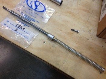
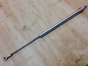
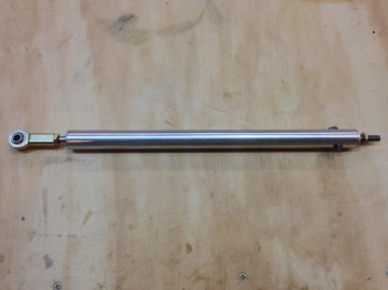
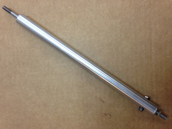
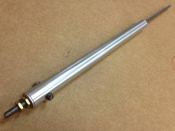
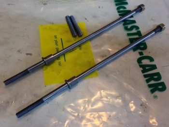
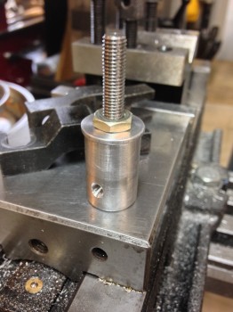
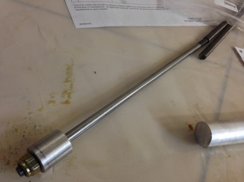
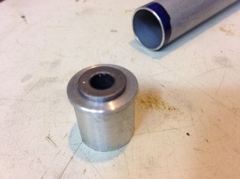
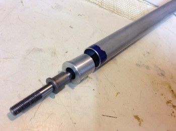
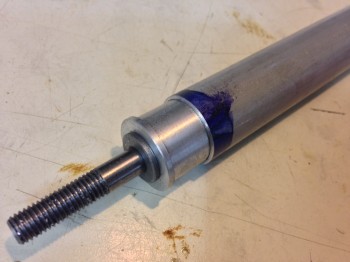
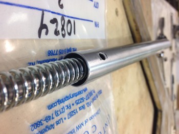
The Atkinson Pitch Trim System project marches on!  After receiving new parts and materials, Marco has machined some simply beautiful spring housing assemblies. Which, speaking of springs, they seem to be the most problematic part of this whole endeavor.

Chap 17 - Atkinson Pitch TrimChap 17 - Atkinson Pitch Trim

When Vance designed and built this pitch trim assembly back in the 1990’s, apparently both True Value and Ace hardware stores carried a spring known as “Compression Spring p/n 196.”  Well, after emailing, calling and perusing a half-dozen True Value and Ace hardware stores–and those big Blue and Orange guys as well–for those of you that are interested, I can assure you that that spring is no longer in their inventory.  Nor anything close to it to serve as a suitable substitute.

However, after one Amazon & two Century Spring Co. orders for springs (I won’t bore you with Century Spring’s minimum order amount), it looks like we finally found a suitable spring, and possibly one viable candidate . . . subject to testing of course.

Chap 17 - Aktinson Pitch TrimChap 17 - Atkinson Pitch TrimNow that we have a viable set of springs, and can use those specs to narrow in our search for some springs that let us lock in our control forces (FYI – Vance had three sets of springs [that fit!] that he tried out before getting the right “feel” on the pitch controls).

Chap 17 - Atkinson Pitch TrimChap 17 - Atkinson Pitch TrimIn addition, I’ll be ordering the actuator this week so that at least initial testing can begin, which will help in selecting some further spring candidates.


Chapter 22 – Instrument Panel Ongoings

Chap 22 - Garmin G3X Touch

After squawking about the new Garmin G3X Touch being too expansive for my wee panel, I decided that I should thoroughly investigate it to ensure I wasn’t missing anything important.  So this past weekend I again built a matrix to compare all my EFIS options to ensure that I’m getting the best capabilities, cost benefits, and of course weight efficiency out of my EFIS that I possibly can.  Thus, I did a runoff betwixt the new Garmin G3X Touch, threw the close-sized GRT HXr 10.4 back into the mix, the GRT HX 8.4, and GRT HX 6.5.

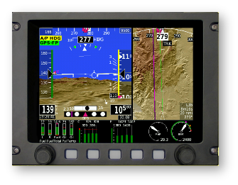
Chap 22 - GRT HXr 10.4 EFISChap 22 - GRT HX EFIS

I then began to tally up all the weight, cost & current draw of all the components required to give me the capabilities I’m looking for in an EFIS system.  Something to note that in all of these configurations is that the second-screen MFD and back-up PFD is the GRT Mini-X.
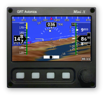
Chap 22 - GRT Mini-X EFIS

I was surprised as I tallied up the prices that the cost difference between the Garmin G3X Touch and the GRT HXr was less than a grand.  As I trudged along in looking up component weights, and with things still looking comparable between the two systems (of course giving a slight performance edge in touchscreen simplicity to the Garmin), I hit a fairly significant snag.  It appears that Garmin’s remote transponder is a robust bubba, weighing in at over 3.4 pounds with an installation depth of over 11 inches. The weight on this one transponder helped get me back to reality, realizing that I was comparing the big heavy guys, when once again I was getting plenty of capability with the smaller, very capable “little guy” EFISs that were much lighter and offered much more panel space … and thus configuration options.  So once again, although tempted by cool colors and touchscreens, I dumped the big EFISs to return to smaller, lighter and more efficient.

One thing that came out of my EFIS comparison, was that I took a hard look at my allowable space BEHIND the instrument panel.  I pulled out the plan’s A-pages to measure out clearances and I had a true Doh! moment.  Albeit initially (Fall 2012) I had been verifying clearances behind the panel with cardboard mockups, since then I had been rearranging, adding, removing and modifying my avionics/instruments with apparent reckless abandon!  The result was that I was placing components in position on the front panel with assumed clearance behind the panel.

To remedy my ways, I gathered the physical data for the displays, avionics, instruments and components all going into the panel.  I clearly needed to deconflict my behind-the- panel space requirements to match what I could have on the front of the panel.  I will say that I attribute this epiphany in part to Nick Ugolini since I found while reviewing his blog that he had run into this snag while redoing his instrument panel.

A significant focus in this effort is of course the area immediately behind the lower right side panel, since the elevator control rod must have free reign in its movements.  I had stacked up my GNS430W/GTN650 over on the right side, having failed to verify it’s clearance with the elevator control rod, and then even added a couple of other rather deep instruments to boot.  I’m glad I found it now, but I admit it was not the most optimized planning on my part.

The result of all this was a trip back to the proverbial drawing board.  I got out my cardboard cutouts and begin putting all the “new” puzzle pieces in place.  The result is something along the lines of this:
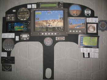
Chap 22 - Instrument PanelAgain, I will make note that this is still a work in progress, but at least now I am very cautious about my specific clearances behind the panel.  In the back of my mind I thought I was doing this, but pulling out the actual plans verified and confirmed how little space there actually is behind our panels in these birds.  And of course we all know what assumptions get us!

Build on!
 

Chapter 22 – Electrical & Avionics Banalities

So I’ve been working on my electrical system. I upgraded my electrical system diagrams from a Garmin GNS430W to the GTN650. I figure by the time I buy my main Nav GPS I won’t be wanting technology that’s on Garmin’s eventual chopping block for support. Of course with the move to the GTN650, I had to add two more Circuit Breakers to the panel since it’s a mandatory requirement for them that you use CBs and not fuses. Although admittedly two CBs for 7 wires is not bad.

I’ve also been spending some time on my throttle and stick (HOTAS) switches.  I reconfigured a number of switches between panel, throttle and stick, and in doing so was able to get rid of a couple panel switches.

Right now I’m thinking that if one has the panel real estate that the new Garmin G3X Touch is the way to go. As for me, I’m not burning that much real estate for an EFIS display. I decided that quite a while ago when I made a decision to forego the 10.4″ GRT HXr PFD for GRT’s much more manageable 8.4″ or 6.5″ PFD. Plus, as awesome as Garmin is, those bubbas tend not to play well with others’ stuff. I guess it’s a good marketing strategy, but picking up and using cool & useful third party stuff with Garmin can be problematic if ‘Big Brother G’ simply says, “No, you can’t use that crap with our suite of technological goodies! Here, use this nice GARMIN thing X instead!”

Also, now that I’m getting significantly closer to my final instrument panel and electrical system configuration, I’ve started building all my Wire Book templates.  I have about 20 total templates currently completed for all the various electrical subsystems, and I’ve built 5 system diagrams from these templates so far.  It should be slow steady progress over the next few months since each one that I build helps with building the remaining ones.

Chapter 17 – Atkinson EZ Electric Trim System

Since January I’ve had an ongoing email conversation with Vance Atkinson about his venerable EZ Electric Trim System.  Vance’s pitch trim system is similar in a vein to the Strong pitch system in that it acts both in a linear motion, and some what parallel to the control inputs… or at least much more oblique than a Davenport leaf spring pitch trim system.  From what I’ve read though, and not having personally flown behind any of them, the Strong system has had both good and bad reports.  The Davenport system seems to get high marks, but it’s significantly heavier and in my configuration would need to be mounted on the center instrument panel leg post, and I want to free up that space for other components while of course saving weight.  Moreover, the Atkinson pitch trim system uses an aircraft quality actuator and the spring assembly is made of aircraft grade metals.

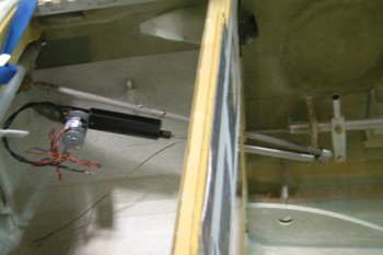
Below is a picture of Bernie Siu’s Atkinson pitch trim system that he installed in his Cozy. As can be seen, the trim assembly mounts out of the way on the side of the fuselage just forward of the panel, and connects to the elevator control rod via rod end.  Bernie has a great detailed explanation of his experience with both the Strong and Atkinson systems here.

Chap 17 - Atkinson Pitch Trim

So, after some discussions with my building buddy Marco, we decided to pull the trigger and make a couple of these guys.  As per usual, I provided the financial backing and he provided the talent!  (ha!)  I ordered the materials and hardware required for two of these suckers and had it all sent to Marco’s production shop of magic and wonder.

Not surprisingly, within short order (mere minutes most likely!) of receiving the required stuff, Marco had worked his machinist’s magic on his lathe and mill to give us the beginnings of two beautiful Atkinson EZ Electric Trim Systems.

Chap 17 - Atkinson Pitch TrimChap 17 - Atkinson Pitch Trim

Chap 17 - Atkinson Pitch TrimChap 17 - Atkinson Pitch TrimChap 17 - Atkinson Pitch TrimChap 17 - Atkinson Pitch Trim

Of course, once again, Marco has done some masterful work and produced some amazingly beautiful machined pieces!   (Bravo my friend!)


Chapter 22 – Behind the Scenes

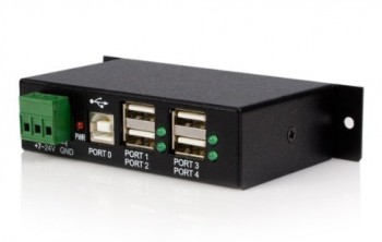
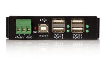
Today I finally pulled the trigger on some behind the scenes–or rather, behind the panel–components.  While some EFIS systems like Garmin make use of Micro-SD cards for updates, etc, GRT uses USB for software updates, system backups, and historical logging of flight and engine data.  In addition, GRT’s remote BlueTooth capability and the Radenna SkyRadar-DX ADS-B both tie into the system via USB.  To have enough capacity, including having a panel-mounted USB jack, I needed to acquire a USB hub and the remote panel jacks that allow me to simply plug my USB stick right into the panel.

Chap 22 - 4-Port USB Hub

There are a couple industrial strength USB hubs that GRT recommends on the advice of a number of builders that have trial tested these devices.  I opted for the StarTech 4-Port USB Hub because it was significantly cheaper than the other recommended 4-port hub, it got great reviews on Amazon, and its configuration.

Chap 22 - 4-Port USB HubAs for this hub’s configuration, you can see in the pics above that ALL of the inputs for both power and data reside on one side of the hub.  The other recommended hub had inputs on both sides of the hub.  In my opinion, having all the inputs on one side makes it easier in both mounting the hub and in managing the cabling & wiring.

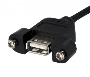
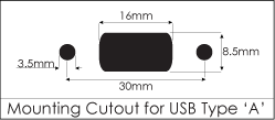
As I mentioned above, in order to tie both the main GRT EFIS and Mini-X EFIS’s rear panel USB ports to the instrument panel in the way of panel-mounted USB jacks, I ordered one cable per EFIS that has a standard USB plug on one end and screw mounted female USB jack on the other.  Obviously this will allow plugging the USB stick in at the panel and give me the same capability as if I was plugging it into the back of the EFIS box.   Below is a pic of the panel side of this cable, and a diagram showing the mounting specs for the jack:

Chap 22 - Panel Mounted USB CableChap 22 - Panel Mount USB