Yes, I haven’t posted in the past week. So what have I been up to?
First off, it took a couple of days for Phil to knock out the extra sanding and buffing on the ailerons. While I was there helping I could see the considerable amount of white paint powder being ground off the surfaces of the ailerons, as Phil aggressively attacked the ailerons.
But then something very strange happened. I had already weighed the ailerons pre-finish and post-paint where they each had gained nearly 8 oz total of weight from micro, primer and paint. If you remember, this is also dialing in the surfaces of the ailerons and the wings to match each other in airflow. So with the weight known, I weighed each aileron again.
Shockingly, with pretty much all the visible orange peel removed on both top and bottoms of the ailerons, and with all the paint powder I saw coming off the ailerons… so much that just by holding them in place while Phil worked I had to wash a bunch of it off my hands, the grand total in net weight removed for aileron was less than 0.5 ounce… barely registerable. Moreover, after this latest round of sanding the bottom of the ailerons, the varying colors of bare glass vs primer is visible under the paint, as the primer was essentially used to finalize low spot fill on these ailerons.
The bottom line is that my ailerons are heavy, as are many in the fleet born out in the testimonies by many forum, newsletter, discussion accounts. I sanded them extremely aggressively pre-finish and was well through a significant bit of the top ply of UNI on both sides.
It is my belief that while there is a solid ounce or two that is cooked into the finish and paint that adds to both the weight and balance issues, my decision now is between stripped, “lumpy” ailerons that seriously risk no longer matching the wing surfaces to get them to weigh slightly less and possibly balance that way, or go full rogue and bust the 0.3 lb added weight allowance by less than 0.1 lb each side to get them into balance. With the caveat that I plan on rebuilding the ailerons (preferable with carbon fiber ala Klaus), I’m choosing the latter.
With my heretical decision made, I ordered some 1/8″ diameter lead “wire” and set about to drill a 1/8″ hole in the upper aft “corner” behind the existing balance weight rod. But since the aileron is 65″ wide I needed a drill bit longer than 33″ to come in from each end to create the channel hole for the 1/8″ lead wire. I started with the 24″ drill bit I had on hand, but clearly that didn’t get me through all the way past center.
After looking for a good day, to no avail, to find a longer 1/8″ drill bit, I decided I needed to make my own. I bought a 36″ piece of 1/8″ steel rod and then used a grinder to create flutes on each side and an angled point on the tip:
 Here we have the new 36″ long 1/8″ diameter drill bit on top, and the shorter actual 24″ drill bit on the bottom.
 With the 1/8″ hole made across the entire aileron, just aft and above the original balance weight, I then slathered up the inside of the hole and the 1/8″ lead wire with wet flox as I cajoled the wire into the hole. Since friction was too much with this soft flexible “wire” to allow me to insert the lead from just one side, I cut it in half and slid the wire in from both ends of the aileron.

I then left the flox-secured lead wire to cure overnight and will assess further after weighing and checking balance on both ailerons.
As an aside, I will also note that Jess and I went out of town for 3 days over the weekend to celebrate our anniversary, which was another big chunk of my plane-building absence.
So in addition to my aileron quagmire, I’ve also been dealing with getting the fuel selector valve and fuel pump final plumbing completed.
I used the cut off piece from the fuel line I deemed unserviceable as a nozzle to allow me to inject 100LL into the EFII fuel boost pump to prime it before testing if it powered on.
 I had set up my video camera on a tripod and was actually planning on making a short video on it, but I started running into issues.
First, after shooting in nearly 2 full large syringes worth of 100LL and flipping the switch, the FUEL PUMP indicator lit up but nothing happened…
I tested the electrical connectors with my multimeter to find that both positive and ground leads were both connected to ground. And that I had also popped the fuse.
After some investigation I found that the positive connector was touching the case, grounding it out (apparently a minor issue in that I found many builders who install these pumps cover the positive connector to prevent this from happening). With my checks looking good, I once again resumed my test.
Strike two! When I flipped the switch nothing happened. After another full round of electrical checks with the multimeter I could find no issues. I then remembered when I was working on my wife’s convertible Mustang top that before filling the pump with oil I had to rap on it a few times to get it to work. I employed the same method here, banging on both cylinders with the handle of my screwdriver.
Voila! It kicked on.
Then STRIKE 3! Wanting to ensure that the boost pump was operating, which it is, I only flipped its switch on for maybe a second to hear it turn on. I then realized that the whole right end compartment under the pilot thigh support was flooded with 100LL. I sopped it up with paper towels and rags and threw those outside to dry, then sprayed and cleaned the area with Simple Green to knock down the fuel smell.

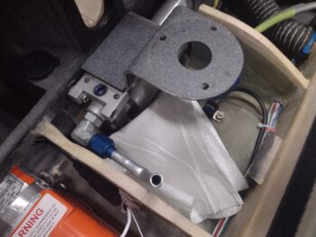
Sins of the past! Somewhere along the route of my fuel boost pump installation I had temporarily installed a standard 45° -4 NPT to -6 AN elbow fitting (shown above) at the pump exit to feed into the engine fuel feed line. And while it does thread in fairly snugly, it is NOT the same threading (I would have gooped it as well for final install).
I’m guessing that since I removed straight blue anodized aluminum fittings to then allow me to install a 90° fitting (from EFII) on the left side, that I assumed the removed fittings were NPT threads. They are not. They are O-Ring Boss (ORB) straight threaded fittings going into each end of the fuel pump (shown below).

As you can see above, I had already configured the geometry of the engine fuel feed line to connect to a 45° fitting vs the 90° fitting sent to me by EFII. At this point, not knowing what thread I was dealing with yet (BSPP? NPSM? ORB?) I called EFII in California about an hour after they opened, but had to leave a voicemail for them to call me back. In the meantime I whittled the thread options down and was fairly certain that it was ORB threads.
I then did a fairly exhaustive search online to find a 45° fitting with ORB threads on one end and -6 AN threads on the other. Thankfully I found a few sources of supply.

STRIKE 4! Yep, during my research in my attempt to find out what thread these fittings were on the pump side, I ran across a statement on EFII’s website in reference to the installation orientation of the fuel pump: “The unit can be mounted in a standing up fashion with the fuel pump above the regulator which is common for installations in tandem aircraft…”
What?!
Let’s look at all the historical reference material that I had on hand from around the time I bought this fuel boost pump. First, here’s a pic from my old installation manual. Note the smaller diameter regulator over the fuel pump (and no description of what components are what).

And another example pic, orientation the same way:

And a newer pic from their website, almost always with the actual fuel pump depicted on the bottom, when it should be on the top (per their statement).

To be fair, there is one older shot with the fuel pump up top, and this is a new pic I’ve never seen before on their website.
To be clear: I’m NOT fragging EFII. I’m just noting why in my mind there was no question that the actual fuel pump was to be mounted on the bottom.

No big deal though, as when I called EFII back towards the end of the day I confirmed that, A) Yes, the fittings do have ORB threads and, B) there is no big issue with the fuel pump on the bottom, it may just take a second or two longer to prime the system.
With that, I ordered a new 45° ORB & -6 AN fitting. Tomorrow I’ll press forward on the ailerons and the fuel selector valve plumbing.
Pressing forward… one issue at a time!

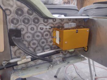 After setting the aileron control tube in its approximate alignment using small plastic CPC pin & socket storage bins… and a screwdriver, I then played around with possible positions and angles of the servo control tube (silver) that connects the servo pivot arm to the aileron control tube (black).
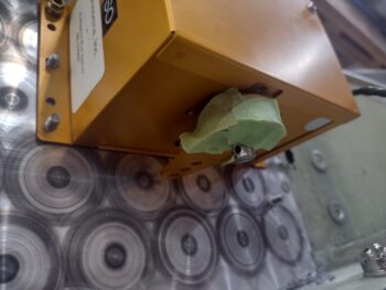 Again, as you can see in pic 1 the servo pivot arm is temporarily taped into place since the 4 screws that secure it have Loctite 222 pre-applied and are reportedly fairly difficult to remove once installed (per manual).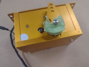
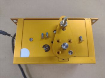
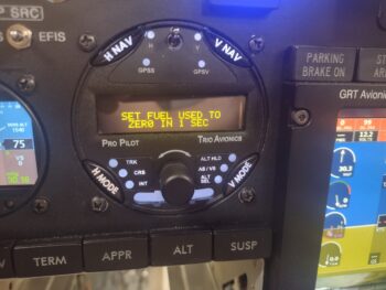
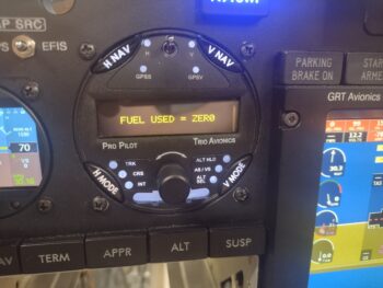
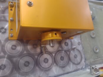 With the roll servo in place on the CS spar, and cables connected up via the Deutsch connector, I then re-installed the screen-replaced Trio Pro Pilot autopilot control head into the panel.
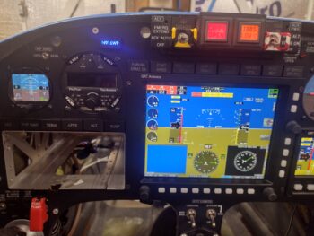 I then fired it up and was pleased to be greeted by an operational screen!
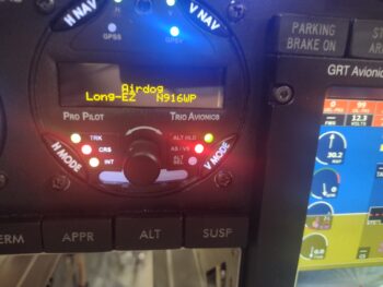 Here’s a couple more screens, which is about all I can show at this point since it doesn’t report much without a GPS signal (which I have none with the bird in my metal shop).