Project Update

Hey Folks,

Well, it’s been a crazy summer… consistently super hot weather that has kept the internal workshop temps well into the mid-90’s to over 100° F, and that’s with fans on.  So I’ve been delving into some other homestead tasks while still trying to get a bit done here and there on the bird.  The hot weather has eased up slightly, so I’ve been spending another 1-2 hours a day more in the shop (before still needing a shower!).

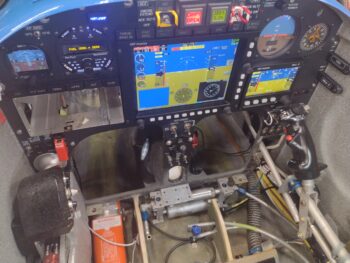
The electrical system and instrument panel install is still virtually complete.  My Trio autopilot is installed and Garmin GNS-480 GPS Navigator and Bendix-King AV8OR handheld GPS back in hand from getting repaired. 

I still need to finalize the weight and balance on the ailerons before their final installation onto the wings.

Also on the upcoming to-do list is the final canopy install… and getting the rudder/brake pedals configured and installed, along with the brake lines, master cylinders and reservoirs plumbed. 

Slowly making progress . . .

Chapter 21 – Fuel valve installed

Today was all about getting the final left fuel line tubing segment made up and installed.

And I’ll note that with the weather temp dropping into the mid-80’s (about 5-6° cooler than the usual lately), it provided a noticeable slight reprieve from this crazy heat of late.

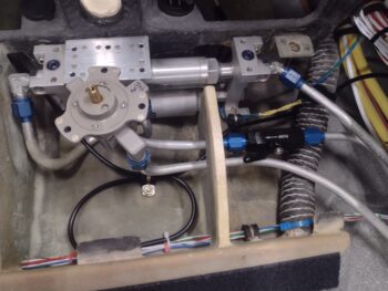
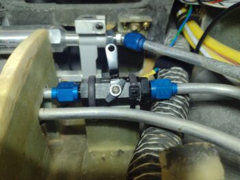
Note the fuel line segment coming from the black inline fuel valve to the fuel selector valve.  It looks a little odd at this camera angle as it looks like a constant shallow curve up into the fuel selector valve.  That is an optical illusion, as there is actually 2 curves at play just below the fuel selector valve: a 90° from vertical-to-horizontal and about a 23° curve forward to place the fuel line somewhat in the center between the aft (right tank) and forward (out to fuel pump) fuel line tubes on the right side of the fuel selector valve [note peel ply pulled and glass edges cleaned up from yesterday’s support pedestal layups].

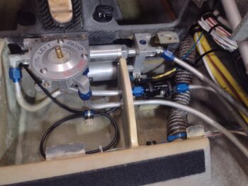
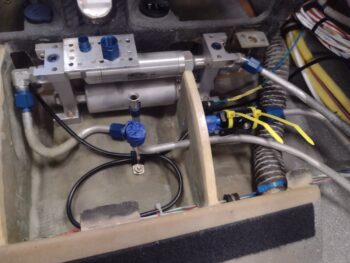
Here’s a bit higher angle of the above pic: note the fuel selector valve “free floating” as it is only secured in this position by the 3 fuel line fittings threaded to hand tightness at this point.

I then installed the fuel selector valve first to the compound angled securing bracket, which involved also installing the valve’s fascia ring plate.

Once the fuel selector valve was secured to the bracket with 3 stainless steel button head screws, it resulted in the bracket being askew —angled off to the right by about 0.3″.  I then rotated the fuel selector valve and bracket CCW and temporarily secured it in place with a hex wrench inserted into a K1000-8 before installing all the mounting CS screws.

I also had to add some space between right fuel line tubing (farthest aft) and the left fuel line inline valve to ensure the open/closed handle could rotate freely.  To further ensure clearance I also rotated the inline valve body to ensure that its top face (flat section) was actually vertical before securing it to the support pedestal with heat shrink covered zip ties.

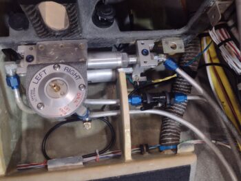
Below you can see the 6x #8 CS screws that secure the fuel selector valve mounting bracket to the lower right angle bracket just below the nose gear viewing window.

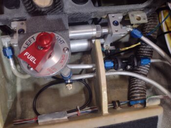
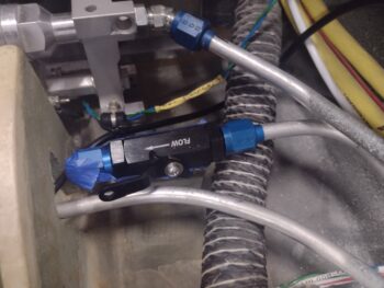
I then installed the fuel selector valve’s rotating handle and the small painted screw cover plate over the bracket securing screws I highlighted above.  Also note that I turned the left fuel line inline valve handle to closed (up) to verify clearance with the nearby right fuel line tubing.

Here is a closer-up shot of the left fuel line inline valve handle in the closed (up) position.  This pic also gives us a better view of the fuel valve support pedestal aft layup after cleanup. Again, when this inline valve is in the open (down) position it will be safety wired to the Adel clamp screw seen at the bottom of the pic above.

And while I’m very pleased with the good progress I made on the fuel system today, I will note that I still have to do the final torques on all the fuel line tubing securing nuts and secure/pad the fuel lines where the contact any composite surfaces.

Chapter 21 – Fuel Valve Support

Today was another barn-burner hot day… I was soaked to the bone in less than 20 minutes.  Thus I’m looking at some type of additional shop cooling options, since layups and such are not designed to be an 80/20 mix of epoxy and sweat!! (I digress…)

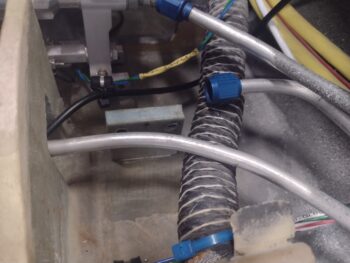
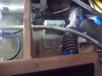
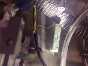
I started off by removing the weights from atop the left fuel line on/off valve, exposing the pair of yellow zip ties that are securing the valve body to the top edge of the foam/fiberglass support pedestal… which by the way measures about 2″ wide x 2.1″ high.

I then cut the zip ties to reveal the position of the left fuel line on/off valve in its unencumbered state.  Also, once installed, I’ll safety wire the valve lever into the open position (as it sits) vs closed, which is 90° up from its current position.

In prep for the final glassing of the valve support pedestal, I removed the valve.

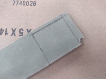
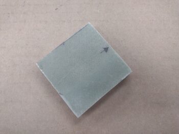
I then prepregged 2 sets of 2-ply BID in 2″ x 2″ squares (yes, a lot of “2”s!)… and after applying a flox fillet in the corners of the support pedestal and fuselage floor, I then laid up the aft side BID tape.  And then peel plied it of course.

I then did the same thing on the front side of the valve support pedestal… the only difference on this side being that the epoxy was getting more gummy since I was using fast hardener and the heat was insane!  But I got ‘er done, just under the wire!

Tomorrow I’ll pull the peel ply and clean up the edges of the cured securing BID before getting to work on the last cross-connect tube between the left fuel line valve and the fuel tank selector valve input port.

Again… pressing forward (hot and slow!!)

Chapter 21 – Fuel Valve Install

Today was another scorcher.  And with that mandatory notice out of the way, my goal for the day was to get as far on trimming and shaping the left fuel feed line to allow for installing an on/off fuel valve.

As I mentioned in my recent video, I WILL NOT be installing a fuel valve for the right fuel line at this point due to time and space constraints.  The 90° bend in the left fuel line up to the fuel selector valve was not a pretty sight, and since it needed reforming, I decided to go ahead and install the left side on/off fuel valve now.

This was pretty much the status of things when I started today . . .
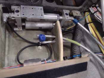
I then cut about 1.5″ off the end of the left fuel line tube to allow me to get it out and free from the transit slot in the thigh support rib.  Of course it’s tight quarter working in this area, so I simply used side cutters for this initial cut.  Then once I positioned the tube where I wanted it, I used my tube bender to place a 90° bend on the tube.

I cut the the tube to length, then slid the anodized blue tube nut and sleeve onto the tubing before flaring it… again, tight quarters!
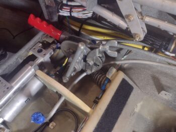
Here’s the newly bent, prepped and flared left fuel line, ready to attach to the fuel on/off valve.
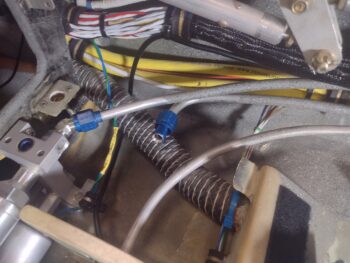
Which I did here to check out fit and alignment…

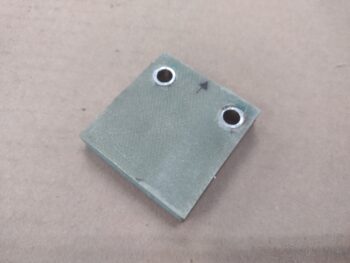
I then spent a good little bit determining the height and angle of where I wanted the fuel valve to allow me to get the width and height of the 3/8″ foam pedestal it will sit atop.
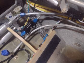
Out of a scrap piece of BID covered 3/8″ thick PVC foam, I then cut out the left fuel line on/off valve mounting pedestal.

Employing the tried and true KISS principle here I simply plan to secure the fuel valve to its mounting pedestal with zip-ties, so I drilled, prepped and micro’d in a couple nubs of -6 3003 aluminum tubing into the top area of the pedestal.
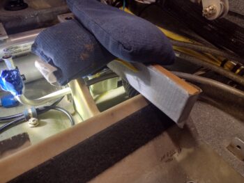
I then zip-tied the fuel valve to the pedestal top edge, slathered up the bottom foam edge of the pedestal with micro and then threaded the fuel valve to the end of the left fuel line.  With the fuel valve fastened to the fuel line, I then did some minor reposition on the pedestal as I weighed it down for curing.
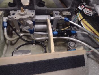
Tomorrow I’ll add a fillet to each side of the pedestal and glass it in place with 2-ply BID tapes before moving on to my final cross-connect fuel line between the on/off valve to the fuel tank selector valve.
Chapter 21/22 – Fuel pump primed

To start off, this summer’s heat has been both persistent and brutal, consistently in the low to mid- 90’s outside… meaning high-90’s to well over 100° F in the shop.  Maybe I’m getting old and wimpy, but being in a full set of work clothes, drenched and dripping with sweat after 15 minutes of working, with shop fans on full high, is just not working for me thus far.  So I set my attention on other tasks that have needed to be done as I await cooler weather temps.

Ok, here’s another shot of the panel —fired up to run the fuel boost pump.

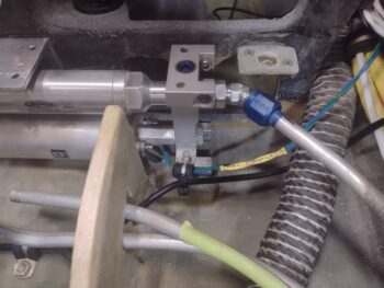
As you can see here, the fuel boost pump has been re-installed, the new 45° fitting is installed on the right side, and the fuel selector valve base mounting plate was installed as well (upper left corner).

I made a fairly short video of the priming of the EFII fuel boost pump…

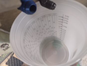
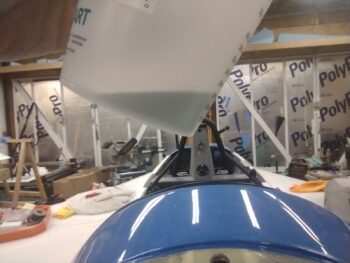
Which I referenced the paint cup on the firewall as a fuel overflow container.  I did in fact need it, so I was of course glad that I secured it under the firewall fuel outlet fitting (black, center top).

And a final shot of the excess 100LL fuel that came out of the firewall fuel outlet fitting.

I’ll note that I also checked all the fuel joints down the right sidewall (as best possible) and found no leaks.

Pressing forward!