Chapter 22 – Panel Labeling Test

This blog post actually spans about a week of some light off and on work.  Most of it I didn’t capture in photos, and even more of it fell in the realm of planning.

One thing I did was check out an option I had for labeling the instrument panel.  It involves printing out a black surrounding background around white lettering (technically the color of the paper).  Once treated with some spray, this becomes like the soak and apply decals we all used on model airplanes we built as kids.

Here are the labels ready to be soaked in water and applied.  The black plate is a spare piece of aluminum that I painted the same color as the instrument panel.

I then noted a significant issue.  When I cut the white substrate paper (above) it creates a white edge on the appliqué. Unless you go straight vinyl letters, the edge of the applied lettering is really what we’re trying to hide, and in this case it is clearly visible with it’s glaring white perimeter.

Unfortunately this test was a resounding NO-GO.

So at this point I think I’ll probably just use my standard P-Touch label maker to label the panel.  Then I’ll clear coat the panel and labels in the same way I did my nose tool box.  In the end I expect it to look very acceptable for what I need.

Chapter 21 – Right Outboard Fuel Rib

Today was all about configurational planning and test fitting the right strake’s outboard fuel rib/wall, which of course is the converted original OD rib.

First off, here’s a quick look at the peel ply on the bottom edge of the layup that secures the extended outboard fuel cell’s aft wall to the outboard side of the R45 rib.  Not sure why during the cure it lifted off a bit in the corner, but after a bit of judicious sanding it will be fine to add more additional glass along that edge.

I then cut the outboard fuel wall rib (again, original OD rib) to shorten it to length to align the tip of it with the very outboard rib (left) and the R45 rib (right).

As you can see, I will need to shape and trim the aft wall of this extended fuel cell both top and bottom to match the contour of the top and bottom strake skins.

Also, as it sits in the pic, the rib itself stands a bit too high for the top skin to fit correctly, so I’ll need to trim it down a hair (note trim line along forward bottom of rib).

Yet another shot of the outboard fuel tank wall rib, which is just the front portion of this converted OD rib.  The aft squarish pocket will not contain fuel.  In fact, after pondering this configuration for a bit, I decided to open up the aft portion of this outboard rib so that moisture doesn’t get trapped inside this enclosed, isolated pocket.

Here’s one last shot of my test fitting the outboard fuel tank rib/wall.  Again, note the trim line along the forward bottom of the rib.

I plan on glassing this rib in within the next day or so, and then will start working on the left side outboard fuel tank wall/rib.  The left will be a bit more entailed since I’ll have to do some pre-configuring on it to allow mounting the 2 GRT EFIS magnetometers.

Chapter 21/22 – Electrons & Fuel

I started out today by installing the strake R45 ribs onto the CS spar front face.  I used 2 plies of BID on the inboard corner and a ply of BID on the outboard corner.

Here’s the left R45 rib floxed and glassed in place.

And here’s the right one.  I did peel ply the inboard layups since I’ll be glassing quite a bit over those corners.

I then took a break from the strakes to let the R45 layups cure.  I cracked open the manual for the Electroair electronic ignition and determined I simply needed to add a significant length of 18 AWG wire from the Battery Bus (on back side of Napster bulkhead) to the D-Deck…. at least that’s what it ended up being.

I also printed a bunch of labels and applied those.  With this wire installed, that only leaves on my list the Trio Autopilot roll servo cable needing to be installed.  Again, that will get installed when the panel electronics get installed.

Quite a few hours later, after the R45 rib layups were cured to the touch, I trimmed the glass and then added another piece to the puzzle…. you can see them just behind both the left and right R45 ribs below . . .

The square pieces I glassed along with the BAB baffle extension pieces.  These pieces extend outboard from the R45 rib perpendicular to it.

Here’s another shot.  I know it would have been easier, and even given more fuel, if I had angled these extended fuel cell back wall’s outboard edge aft.  But I wanted to keep the fuel forward of the line close to the plane’s CG.  Granted, having this piece straight across may make it a bit trickier to bevel and shape to fit into the strake wing-like shape.

Here we a view of the aft side of the new fuel cell’s back wall.

And a couple of shots of the same extended fuel cell aft wall on the left side strake.

My next task on the strake is to trim the modified OD ribs so that they’ll fit parallel to the R45 ribs, glassed to both the CS spar and the new extended fuel cell aft wall.  On the left side the outboard face of the OD rib is where both GRT magnetometers will get mounted.

I’ll be out of town for the next few days, so no building over that time.  I’m hoping when I return that I’ll have no more trips to deal with for a while.

Chapter 21/22 – Pre-strake Wire Runs

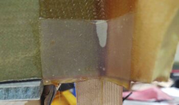
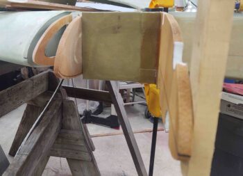
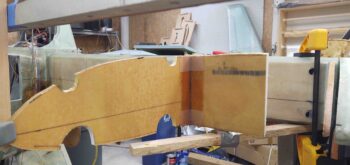
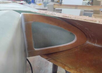
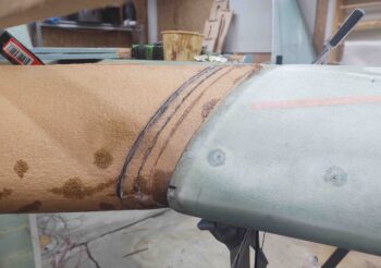
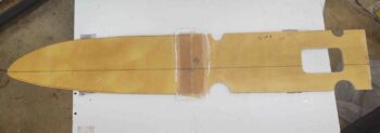
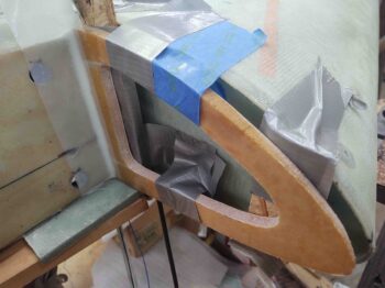
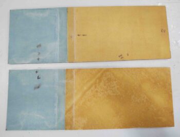
I started off today with a simple 1-ply BID tape (“wet”) layup on the inboard seam of the left strake BL23 rib.  I didn’t grab a pic of my initial layup, but here it is way later in the evening after I pulled the peel ply and cleaned it up.

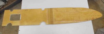
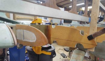
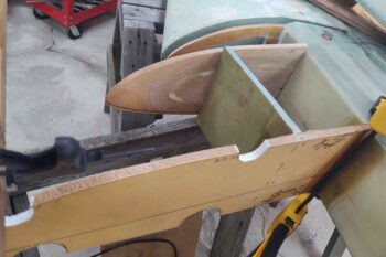
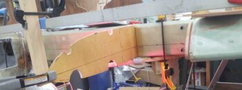
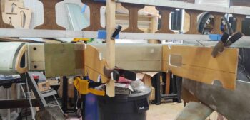
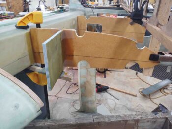
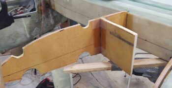
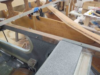
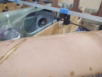
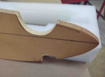
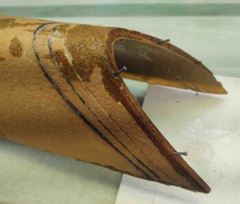
I also determined my “mouse hole” locations on the R45 ribs as well, so I marked and cut those out.  I then cut out the foam in the mouse holes and applied wet micro.

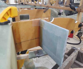
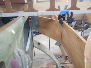
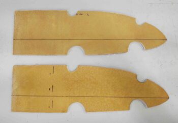
The dashed line on the aft side of the lower R45 rib is where I’ll mount the small square foam pieces that I laid up with the BAB baffle extension pieces, perpendicular to the R45 rib on the outboard side.  This piece will make up the aft wall of the outer fuel cell, with the modified OD rib making up the outer (forward 2/3rds) fuel tank wall.

I then spent the next approximately 12 hours running all the long wire runs inside the fuselage from nose to tail, again, about 30 total.  In short, any wire or cable that would be problematic to install was what I was aiming to get installed pre-strake build.

This effort included a myriad of double-checking and referencing the wiring diagrams to ensure everything was correct, and also a ton of wire labeling.  In fact, I used up an entire cartridge of heat shrink labels on this one job.

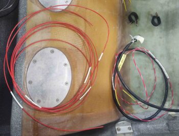
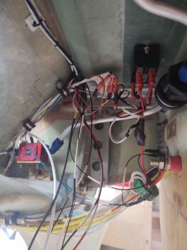
I started with the 2 big yellow power wires that serves as both the starting circuit, and a ground path from the firewall back to the battery.  In Bob Nuckolls’ original Z-13/8 electrical system architecture, he has the positive cable also serve as the alternator’s B lead supplying recharge current back to the battery.  You may recall that this setup pretty much requires the starter contactor be located on the firewall.  I chose to put the starter contactor in the nose, eliminating weight and complexity off the firewall, and run a separate dedicated 8 AWG alternator B lead (white cable below).

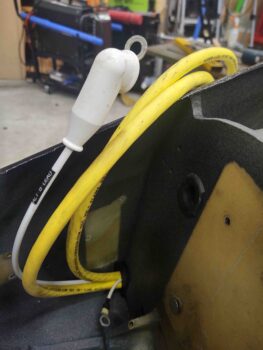
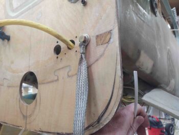
On the firewall end you can see the positive big yellow cable transiting through the firewall to eventually get connected straight to the starter solenoid.  On the hell hole side of the firewall the other big yellow cable, the ground lead, is connected to the other side of the bolt you see securing the braided cable.  There is also a “forrest of tabs” for ground points on the hell hole side connected to this bolt.

The hole just to the left of the big yellow cable is where I’ll attach a red Blue-Sea bulkhead pass-thru with a threaded stud each side.  It’s a bit hefty, but it cleans up the install and it gives me a good termination point on the hell hole side to help secure the Hall-effect sensor that the B lead cable runs through with one wrap.

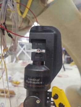
I needed to terminate the alternator B lead with a ring terminal, so I broke out my hydraulic crimper for big wire sizes.  Here I’m just ready to start mashing down the ring terminal onto the wire.

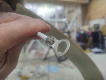
Here’s the result . . .  I don’t think it’s going anywhere!

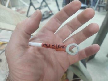
Since I’m out of medium-sized wire labels, I had meant to write neatly on the protective heat shrink before slipping it into place, but I got sidetracked and forgot so I chicken scratched it on just prior to applying heat.  Not pretty, but it communicates what this thing is so I can figure it out years from now!

This is jumping ahead a bit, since this was at the end of the evening after all the wires were run.  You can see the main wire bundle on the aft side of the GIB seat bulkhead secured by 2 adel clamps (middle left).  At lower right you can see the big yellow cables coming from under the gear bow, as well as the alternator B lead terminated and attached to the red colored, threaded Blue-Sea bulkhead pass-thru.

Note just forward of the Blue-Sea pass-thru is the green Hall-effect sensor donut.  It has both the 8 AWG primary alternator B lead wrapped through it and also the 14 AWG SD-8 backup alternator power feed running through it, so that no matter which alternator is live I’ll be able to see the amp level.

What you see in this pic is about all the wiring that will be in the hell hole, with just a small number of wires that will be added…. well over 95% of all the wiring is installed in this area.

To run a number of the long wires down the fuselage I needed to install both the Electroair electronic ignition and the GRT EIS wiring harnesses in the D-deck/GIB headrest housing.

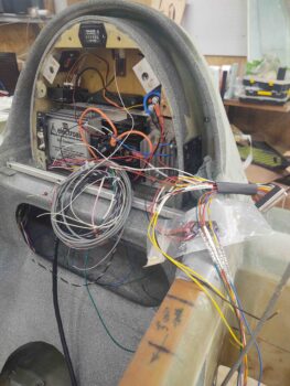
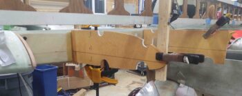
I’ll start from the aft end of the fuselage and move forward with my pics of the installed wiring.  As per Bob Nuckolls, as he spells out in The AeroElectric Connection, I grouped my wires into 2 wire bundles: big power wires (including higher current smaller wires) and smaller low power & data wires.  Moreover, I separated these bundles as much as possible in the limited confines I have available in the fuselage.

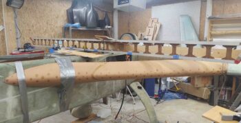
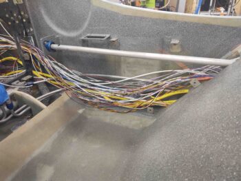
It’s a bit difficult to tell since I don’t have the cables and wires secured yet (but will prior to strake install), but there is a bottom/lower bundle of big wires and above that is a run of all the smaller wires.

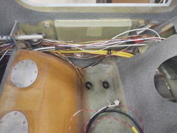
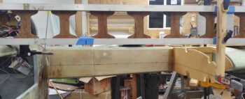
The GIB area just aft of the pilot’s seat.  Again, the wires are (will be) separated into 2 bundles.

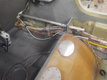
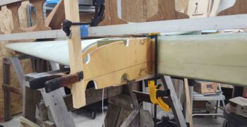
Fuselage wire runs at the front seat right sidewall.

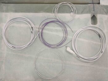
For those that are curious, here’s an inventory of all the wires & cables I installed:

1. Big yellow power cables  (2 cables)
2. 8 AWG B&C alternator B feed
3. #1 6-wire cable
4. #2 6-wire cable
5. Oil heat pump (2 wires)
6. GIB seat warmers (4 wires)
7. Fuel vapor sniffer (3 wire bundle)
8. Trio AP roll servo 
9. AEX laser alt (3 wire bundle)
10. SD-8 b/u alternator power feed
11. E-Bus/SD-8 b/u alternator switch
12. IBBS cutoff lead
13. Spare wire runs (if able)
14. GRT EIS power lead
15. P-Mag switch
16. P-Mag power
17. Trio AP fuel sensor (2 wires)
18. Electroair power
19. Electroair switch
20. Electroair tach select
21. GRT EIS tach select
22. B&C alternator “F” lead
22. Wing taxi/landing lights (2-conductor shielded cable)
23. Wing nav/strobe lights (2-conductor shielded cable)

I was able to get all the wires installed except for the Trio autopilot’s roll servo since it’s a shielded multi-conductor cable that is soldered into the AP’s D-Sub connector.  Since there are a myriad of other connections to the TriParagon, etc. I couldn’t pull the harness so I just left it in the panel mockup.  I did however simply cut the 2 (twisted-pair) wires from the Trio AP harness for the Fuel Flow data feed and will re-splice when I install the panel.

I also need to figure out the Electroair power wire since it’s not on the main Electroair harness but rather hangs off a sub-connector cable which currently is way too long and needs to be trimmed before install.  A mini-job which I plan to tackle over the next day or so.


Chapter 21/22 – Strake tidbits

Today was yet another fairly light build day, although I do have a few pics to share.

I started off by cleaning up the right strake outboard rib layup and then grabbed a shot of it. As you can see, the fit is pretty good inside the strake LE.

I had my little buddy over for a good portion of the day, so most of my time was spent not building.  During a computer-game-playing session I was able to do an inventory of all the long wire/cable runs that will run along the length of the fuselage… around 30 total.

My inventory identified that I was missing 2 wires for the P-Mag Electronic Ignition that I had not made up yet, so I cut and labeled those: an 18 AWG (middle purple) and a 20 AWG (bottom white) wire.

In addition, I labeled the B&C alternator “F” lead wire that was included with the alternator (top), as well as the 8 AWG “B” lead cable (right). Finally, I labeled the #2 6-wire cable (left). I didn’t haven’t large heat shrink labels for these latter 2 cables, so I simply used the ‘ol skool method of attaching a label-maker label and then covering with clear tape.

These wires and cables above are the last ones required to complete all the long electrical connections that I’ll run along the lower right corner of the fuselage prior to doing the final install of the strakes.

Speaking of the strakes, I spent about 45 minutes RE-dialing in the left strake LE install with the outboard edge reconstructed.  I did trim down the outboard again, and got it much closer to the final position.  But it was later in the evening and I wanted to get a layup in, so I left the final tweaking until tomorrow.

Here’s the outboard edge of the left strake and its intersection with the wing.  Again, you can see it needs to be dialed in just a bit more, which I’ll do soon.

I then did the final alignment of the BL23/R23 rib (front and aft) pieces.  I had to trim the aft edge that mates with CS spar at a slight vertical angle, with just a bit off the bottom aft edge to angle the entire rib nose down about 0.1″ at about the midpoint.

Here’s another view of the BL23/R23 rib.

I then set the newly extended BAB baffle in place to test out my extension and see how it all fit.

Here we have a view of what the strake baggage area will look like: size and configuration.

I need to trim a hair off the height of the new BAB baffle piece to get it to slide all the way into the fuselage strake opening, but so far it all looks good.

And a shot of the newly extended BAB baffle from inside of the fuselage looking out.

I then glassed the left side aft BL23 baffle to the forward R23 rib.  I used 2 plies of BID, and to cover a decent-sized dry patch on the front edge of the BL23 baffle I went with a 3″ wide BID tape.

I’ll point out here that on any fuel tank perimeter intersection or seam I’ll be using 2-plies of BID vs. the plans requirement of only one.  For junctions and seams internal to the fuel tank I’ll still only be using a single ply of BID, as per plans.

I peel plied the layup, keeping it nice and wet.  To note, as per Gary Hunter I am only peel plying layups that will get subsequent glass and secondary bonds later.

Since the front 3/4 of the R45 ribs are no longer the outboard fuel tank wall in my modified configuration (again, to add a bit of fuel outboard to account for fuel lost on the inboard “elbow room” mod), with the OD rib being the new outboard fuel tank wall, I needed to make some mouse holes in the R45 rib.

Here are the front mouse holes on the right strake R45 rib.  I used the remainder of the micro from the above layup to fill in the foam edge of the lower mouse hole.

I then called it a night and left my epoxy stuff to dry overnight.


Chapter 21 – New BABs

Today was a rather light work day, but I did get some significant stuff done.

First off, I glassed the strake baggage compartment side junctions of the newly extended BAB baffles with a 1-ply BID tape.  I then peel plied the layups.

I then added the last piece (with micro) in my reconstruction of the outboard end of the left strake leading edge structure to allow me to recut and fit it at the appropriate length.

Associated with my corrective action above on the left strake leading edge, I also cut, trimmed and shaped the left strake outboard rib and micro/glassed it into place.

Later in the evening I pulled the peel ply off the extended BAB baffles, razor trimmed the glass and cleaned up the layups.

These new BABs are now ready for install.

Tomorrow I’ll continue with some more glassing as I prepare to finish my strake trial fit and assembly, to then start assembling the strake for real.