I started off today with a simple 1-ply BID tape (“wet”) layup on the inboard seam of the left strake BL23 rib. I didn’t grab a pic of my initial layup, but here it is way later in the evening after I pulled the peel ply and cleaned it up.
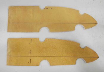
I also determined my “mouse hole” locations on the R45 ribs as well, so I marked and cut those out. I then cut out the foam in the mouse holes and applied wet micro.
The dashed line on the aft side of the lower R45 rib is where I’ll mount the small square foam pieces that I laid up with the BAB baffle extension pieces, perpendicular to the R45 rib on the outboard side. This piece will make up the aft wall of the outer fuel cell, with the modified OD rib making up the outer (forward 2/3rds) fuel tank wall.
I then spent the next approximately 12 hours running all the long wire runs inside the fuselage from nose to tail, again, about 30 total. In short, any wire or cable that would be problematic to install was what I was aiming to get installed pre-strake build.
This effort included a myriad of double-checking and referencing the wiring diagrams to ensure everything was correct, and also a ton of wire labeling. In fact, I used up an entire cartridge of heat shrink labels on this one job.
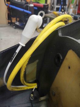
I started with the 2 big yellow power wires that serves as both the starting circuit, and a ground path from the firewall back to the battery. In Bob Nuckolls’ original Z-13/8 electrical system architecture, he has the positive cable also serve as the alternator’s B lead supplying recharge current back to the battery. You may recall that this setup pretty much requires the starter contactor be located on the firewall. I chose to put the starter contactor in the nose, eliminating weight and complexity off the firewall, and run a separate dedicated 8 AWG alternator B lead (white cable below).
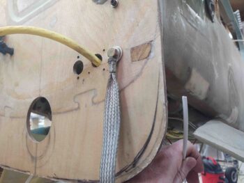
On the firewall end you can see the positive big yellow cable transiting through the firewall to eventually get connected straight to the starter solenoid. On the hell hole side of the firewall the other big yellow cable, the ground lead, is connected to the other side of the bolt you see securing the braided cable. There is also a “forrest of tabs” for ground points on the hell hole side connected to this bolt.
The hole just to the left of the big yellow cable is where I’ll attach a red Blue-Sea bulkhead pass-thru with a threaded stud each side. It’s a bit hefty, but it cleans up the install and it gives me a good termination point on the hell hole side to help secure the Hall-effect sensor that the B lead cable runs through with one wrap.
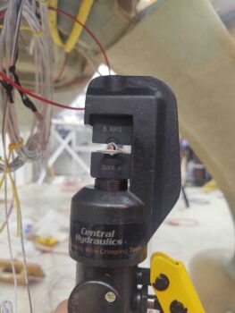
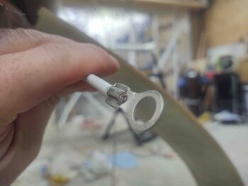
I needed to terminate the alternator B lead with a ring terminal, so I broke out my hydraulic crimper for big wire sizes. Here I’m just ready to start mashing down the ring terminal onto the wire.
Here’s the result . . . I don’t think it’s going anywhere!
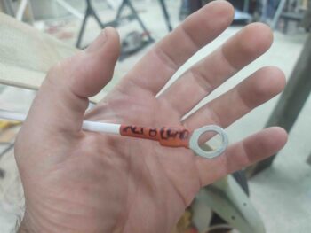
Since I’m out of medium-sized wire labels, I had meant to write neatly on the protective heat shrink before slipping it into place, but I got sidetracked and forgot so I chicken scratched it on just prior to applying heat. Not pretty, but it communicates what this thing is so I can figure it out years from now!
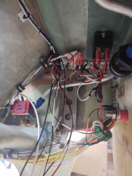
This is jumping ahead a bit, since this was at the end of the evening after all the wires were run. You can see the main wire bundle on the aft side of the GIB seat bulkhead secured by 2 adel clamps (middle left). At lower right you can see the big yellow cables coming from under the gear bow, as well as the alternator B lead terminated and attached to the red colored, threaded Blue-Sea bulkhead pass-thru.
Note just forward of the Blue-Sea pass-thru is the green Hall-effect sensor donut. It has both the 8 AWG primary alternator B lead wrapped through it and also the 14 AWG SD-8 backup alternator power feed running through it, so that no matter which alternator is live I’ll be able to see the amp level.
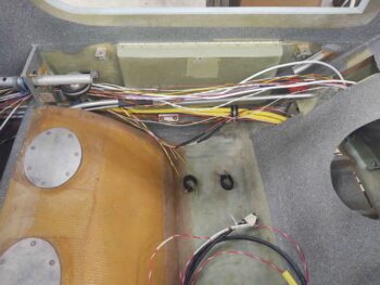
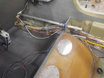
What you see in this pic is about all the wiring that will be in the hell hole, with just a small number of wires that will be added…. well over 95% of all the wiring is installed in this area.
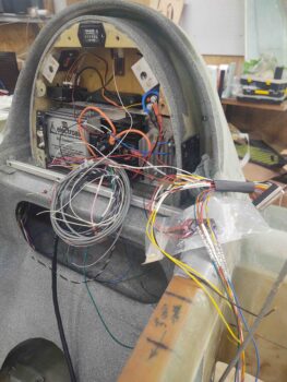
To run a number of the long wires down the fuselage I needed to install both the Electroair electronic ignition and the GRT EIS wiring harnesses in the D-deck/GIB headrest housing.
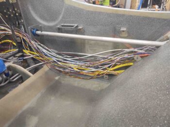
I’ll start from the aft end of the fuselage and move forward with my pics of the installed wiring. As per Bob Nuckolls, as he spells out in The AeroElectric Connection, I grouped my wires into 2 wire bundles: big power wires (including higher current smaller wires) and smaller low power & data wires. Moreover, I separated these bundles as much as possible in the limited confines I have available in the fuselage.
It’s a bit difficult to tell since I don’t have the cables and wires secured yet (but will prior to strake install), but there is a bottom/lower bundle of big wires and above that is a run of all the smaller wires.
The GIB area just aft of the pilot’s seat. Again, the wires are (will be) separated into 2 bundles.
Fuselage wire runs at the front seat right sidewall.
For those that are curious, here’s an inventory of all the wires & cables I installed:
1. Big yellow power cables (2 cables)
2. 8 AWG B&C alternator B feed
3. #1 6-wire cable
4. #2 6-wire cable
5. Oil heat pump (2 wires)
6. GIB seat warmers (4 wires)
7. Fuel vapor sniffer (3 wire bundle)
8. Trio AP roll servo
9. AEX laser alt (3 wire bundle)
10. SD-8 b/u alternator power feed
11. E-Bus/SD-8 b/u alternator switch
12. IBBS cutoff lead
13. Spare wire runs (if able)
14. GRT EIS power lead
15. P-Mag switch
16. P-Mag power
17. Trio AP fuel sensor (2 wires)
18. Electroair power
19. Electroair switch
20. Electroair tach select
21. GRT EIS tach select
22. B&C alternator “F” lead
22. Wing taxi/landing lights (2-conductor shielded cable)
23. Wing nav/strobe lights (2-conductor shielded cable)
I was able to get all the wires installed except for the Trio autopilot’s roll servo since it’s a shielded multi-conductor cable that is soldered into the AP’s D-Sub connector. Since there are a myriad of other connections to the TriParagon, etc. I couldn’t pull the harness so I just left it in the panel mockup. I did however simply cut the 2 (twisted-pair) wires from the Trio AP harness for the Fuel Flow data feed and will re-splice when I install the panel.
I also need to figure out the Electroair power wire since it’s not on the main Electroair harness but rather hangs off a sub-connector cable which currently is way too long and needs to be trimmed before install. A mini-job which I plan to tackle over the next day or so.


