
Today was yet another fairly light build day, although I do have a few pics to share.
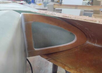
I started off by cleaning up the right strake outboard rib layup and then grabbed a shot of it. As you can see, the fit is pretty good inside the strake LE.
I had my little buddy over for a good portion of the day, so most of my time was spent not building. During a computer-game-playing session I was able to do an inventory of all the long wire/cable runs that will run along the length of the fuselage… around 30 total.
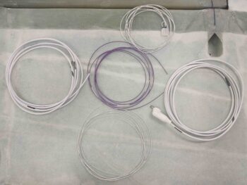
My inventory identified that I was missing 2 wires for the P-Mag Electronic Ignition that I had not made up yet, so I cut and labeled those: an 18 AWG (middle purple) and a 20 AWG (bottom white) wire.
In addition, I labeled the B&C alternator “F” lead wire that was included with the alternator (top), as well as the 8 AWG “B” lead cable (right). Finally, I labeled the #2 6-wire cable (left). I didn’t haven’t large heat shrink labels for these latter 2 cables, so I simply used the ‘ol skool method of attaching a label-maker label and then covering with clear tape.
These wires and cables above are the last ones required to complete all the long electrical connections that I’ll run along the lower right corner of the fuselage prior to doing the final install of the strakes.
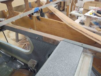
Speaking of the strakes, I spent about 45 minutes RE-dialing in the left strake LE install with the outboard edge reconstructed. I did trim down the outboard again, and got it much closer to the final position. But it was later in the evening and I wanted to get a layup in, so I left the final tweaking until tomorrow.
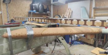
Here’s the outboard edge of the left strake and its intersection with the wing. Again, you can see it needs to be dialed in just a bit more, which I’ll do soon.
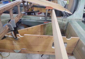
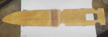
I then did the final alignment of the BL23/R23 rib (front and aft) pieces. I had to trim the aft edge that mates with CS spar at a slight vertical angle, with just a bit off the bottom aft edge to angle the entire rib nose down about 0.1″ at about the midpoint.
Here’s another view of the BL23/R23 rib.
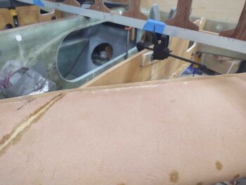
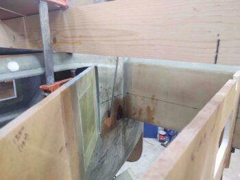
I then set the newly extended BAB baffle in place to test out my extension and see how it all fit.
Here we have a view of what the strake baggage area will look like: size and configuration.
I need to trim a hair off the height of the new BAB baffle piece to get it to slide all the way into the fuselage strake opening, but so far it all looks good.
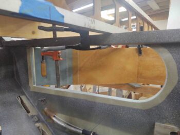
And a shot of the newly extended BAB baffle from inside of the fuselage looking out.
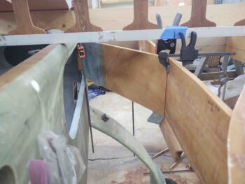
I then glassed the left side aft BL23 baffle to the forward R23 rib. I used 2 plies of BID, and to cover a decent-sized dry patch on the front edge of the BL23 baffle I went with a 3″ wide BID tape.
I’ll point out here that on any fuel tank perimeter intersection or seam I’ll be using 2-plies of BID vs. the plans requirement of only one. For junctions and seams internal to the fuel tank I’ll still only be using a single ply of BID, as per plans.
I peel plied the layup, keeping it nice and wet. To note, as per Gary Hunter I am only peel plying layups that will get subsequent glass and secondary bonds later.
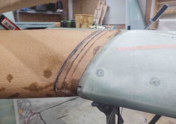
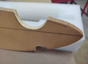
Since the front 3/4 of the R45 ribs are no longer the outboard fuel tank wall in my modified configuration (again, to add a bit of fuel outboard to account for fuel lost on the inboard “elbow room” mod), with the OD rib being the new outboard fuel tank wall, I needed to make some mouse holes in the R45 rib.
Here are the front mouse holes on the right strake R45 rib. I used the remainder of the micro from the above layup to fill in the foam edge of the lower mouse hole.
I then called it a night and left my epoxy stuff to dry overnight.