Shear Web Construction . . . a couple of points of note.
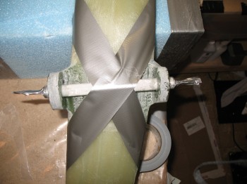
First, I don’t think I’ve really covered what a shear web is exactly. Partly, because I don’t know exactly. Why? Because I’m not a friggin’ engineer! A shear web is glassed using UNI in a hatch pattern that crosses the front of the current “top” of the wing (not the front portion that is rounded, but about halfway back and running down the entire middle of the wing).
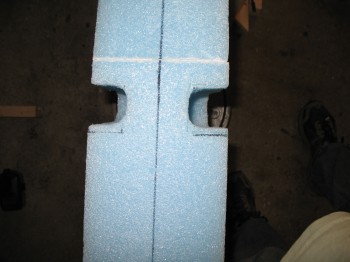
The shear web starts on the top, travels forward 3″, then turns down the face of the shear web cap (again, this is in the middle of the wing) and then moves rearward 3″. In essence, it creates a Π shape cap when the wing is positioned pointed upwards, as it is in the jig. In this position, after the shear web is glassed, the front portion of the wing will get micro’d to the shear web and sit on the top of Π. Once it all cures, and the wing is an entire unit, the left & right sides of Π will be recessed, deeper at the middle and shallower at the wing tip. Then 3″ UNI tape will be laid in long strands onto the sides of Π in these recessed channels. (3″ UNI is not the same as UNI cloth, but very long thick strands of fiberglass traveling in one direction that essential cures into what can be described as a solid glass bar).
When the 3″ UNI tape is laid on the left & right side of Π which is actually the top of bottom of the wing, these create spar caps on the top and bottom of the wing. These spar caps are connected to each other via the shear web, so that all the torsional forces that act on the wing in flight (bending, flexing, twisting) are transmitted from the top spar cap to the bottom, and vice versa through the shear web. If the shear web was not present and it was only the spar caps, the wing foam alone could not handle the flight loads… and bad things would happen. Thus sayeth Burt . . . (well, kinda, with a little paraphrasing!)
Next, after a multi-hour long discussion with Randi (of the infamous Cozy Girrrls) a few weeks ago, I had acquired “the plan” on how to more easily lay up the shear web–again, using poor man’s pre-preg with a twist: aluminum foil– and the secrets for laying up the 3″ UNI tape spar caps.
Thus, without any further loquaciousness, I will get on with the build log . . .
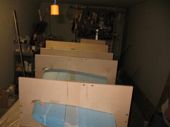
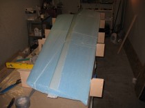
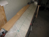
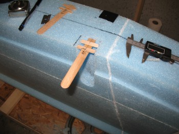
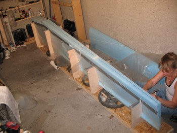
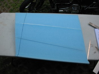
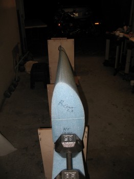
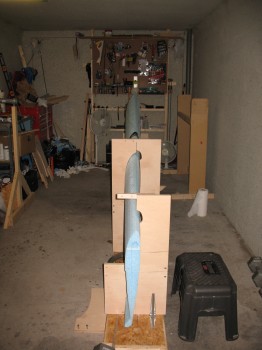
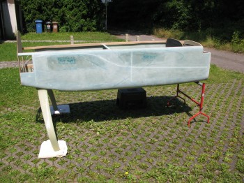
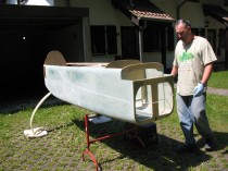
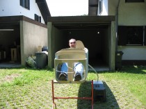
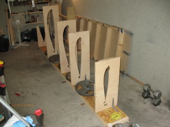
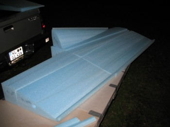
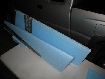
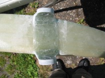
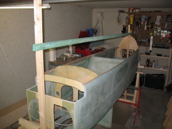
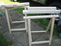
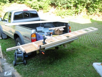
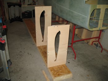
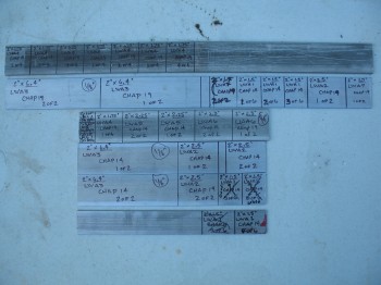
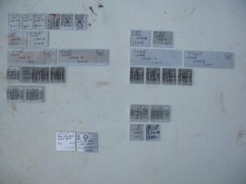
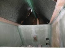
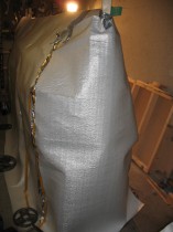
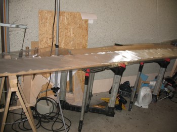
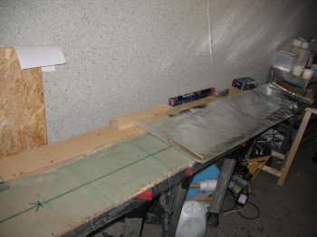
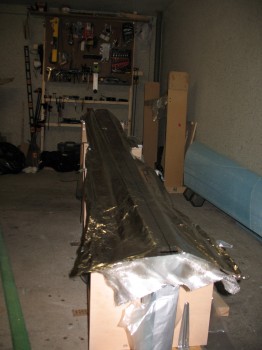
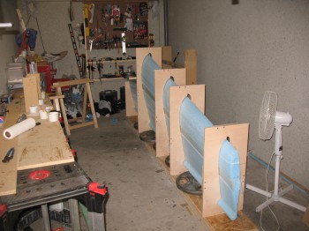
I arranged some saw horses and prepped a long table for the shear web pre-preg. I then measured, drew & marked up the plastic sheeting. I prepped the wing foam at the shear web site & then pre-deployed epoxy & other glassing materials to the shop. I laid out all the UNI glass (that was cut last night) & double checked everything one last time.
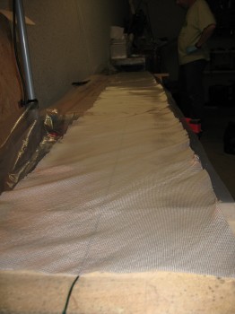
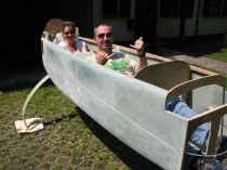
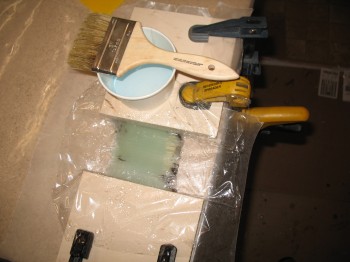
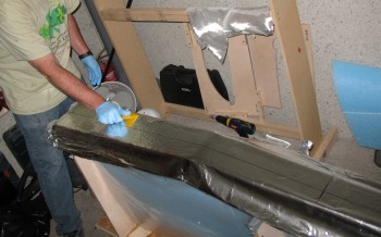
With Gina manning the epoxy production station (again, so NICE to have help!) I wetted out the UNI shear web pre-preg.
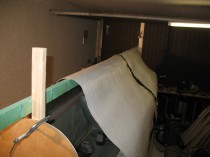
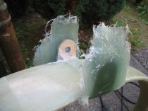
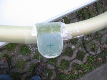
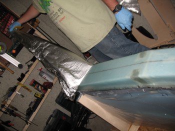
Once the pre-preg was good & wetted out, I micro’d the shear web foam. I then replaced one of the plastic pre-preg sides with aluminum foil and translated the markings to the aluminum foil (these markings showed the center of the layup, both wing ends, and the 2 important “butt lines” [distance from aircraft centerline] that denoted the differences in UNI ply count). I then flipped the entire pre-preg set-up & pulled off the remaining layer of plastic so that only the UNI plies were left attached to the aluminum foil.
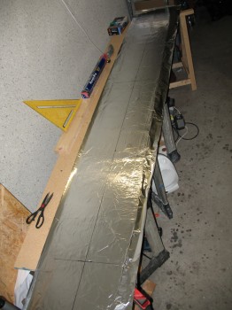
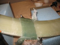
We then transferred the entire UNI pre-preg layup to the wing assembly and flipped it like a flapjack onto the micro’d shear web foam. After getting all the markings aligned, we started vigorously squeegeeing the aluminum foil from the centerline of the layup out to remove any air & to set the glass onto the micro’d foam. The aluminum foil was much stronger then I imagined it would be and really allowed for some hearty squeegeeing action.
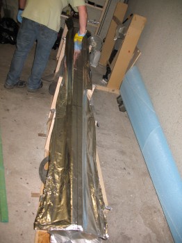
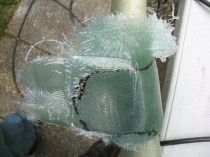
After getting the glass squeegeed out & set, I began to pull sections of the aluminum foil off the layup and cut the edge of the glass with another Cozy Girrrl indorsed tool: “Dritz” electronic scissors. I cannot even begin to tell any composites builder how amazing these scissors are & what a huge time-saver they turned out to be! 5-stars across the board on the Dritz scissors. If you are a canard builder, get these scissors if you don’t have them. Ok, I digress.
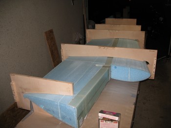
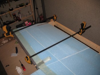
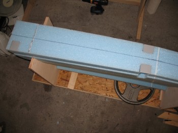
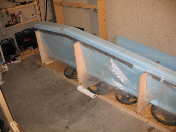
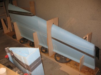
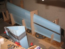
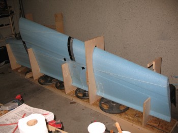
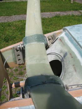
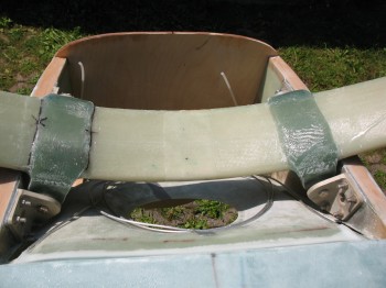
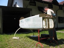
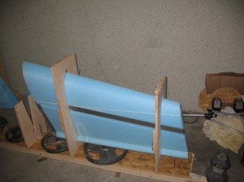
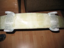
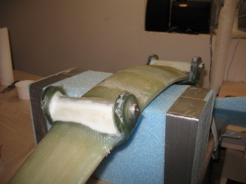
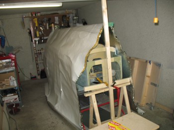
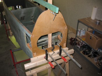
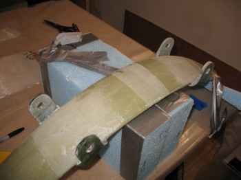
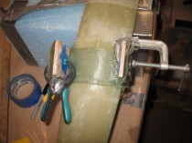
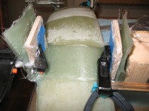
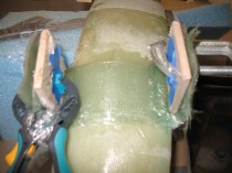
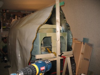
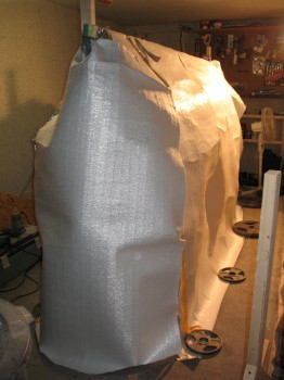
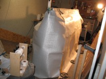
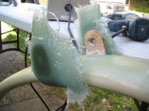
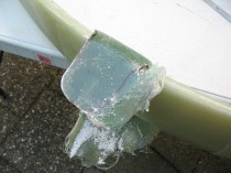
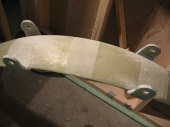
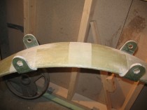
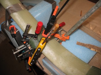
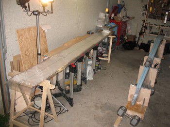
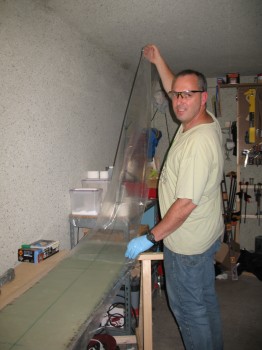
After the UNI shear web was laid up, but with the epoxy still wet, it was time to attach the front portion of the wing (on top in this position). We applied micro to the bottom of the FC4/5 assembly and then positioned it onto the shear-webbed aft wing assembly, and then peel plied the “sides” of the shear web (at this point technically the “sides” of the shear web are really “spar caps”). Also, to ensure that the front portion of the wing was properly aligned with the rear part, all the jigs were re-bolted back together, encasing the new wing structure.
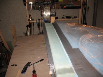
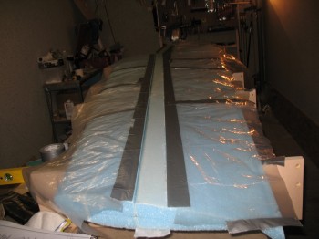
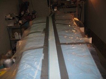
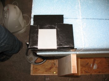
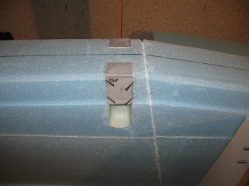
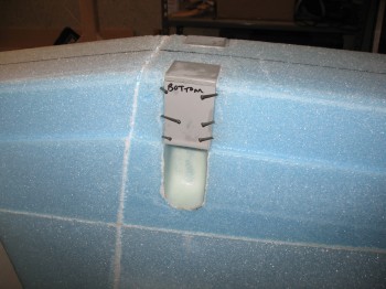
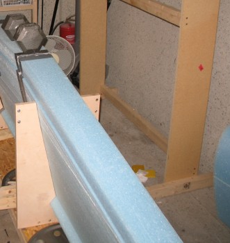
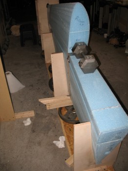
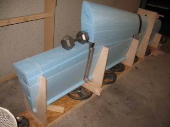
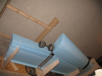
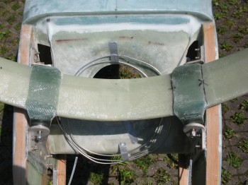
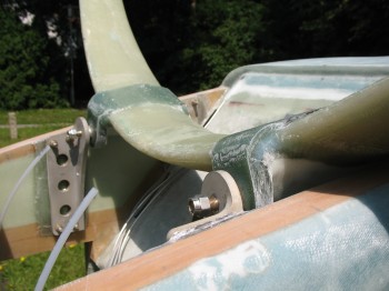
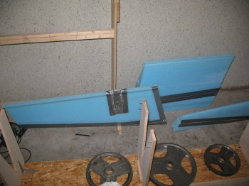
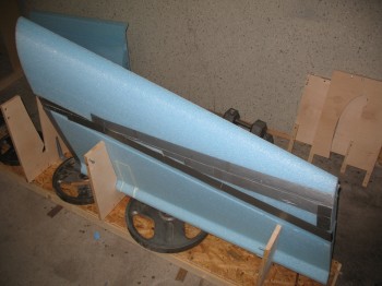
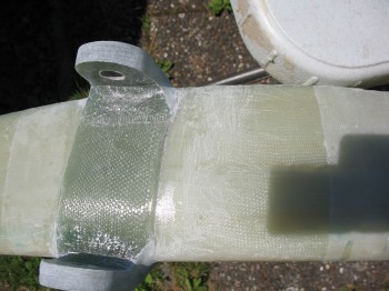
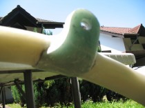
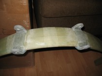
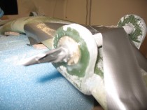
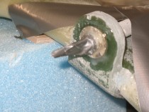
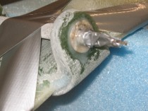
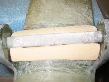
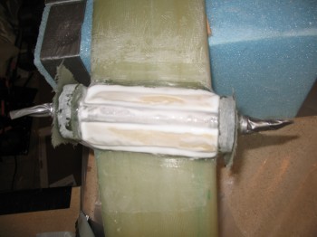
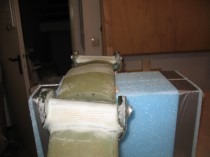
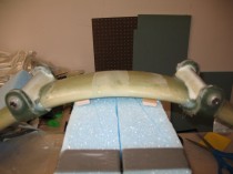
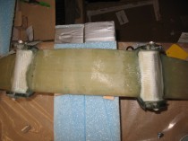
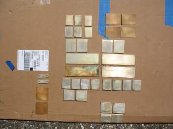
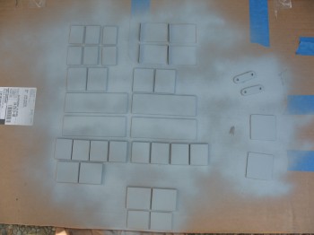
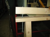
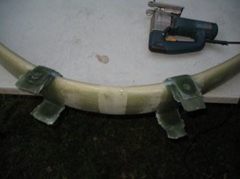
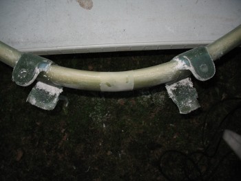
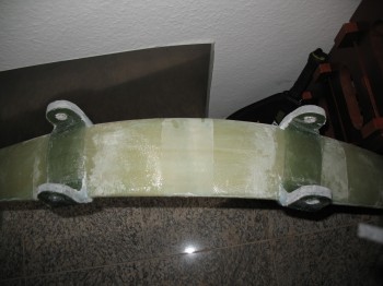
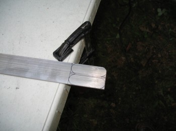
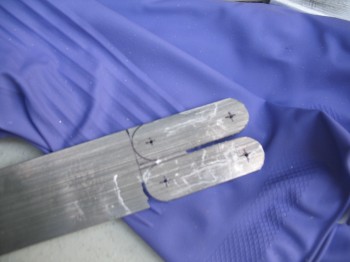
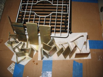
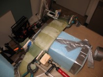
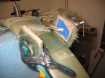
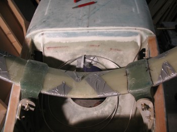
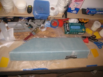
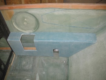
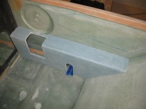
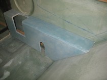
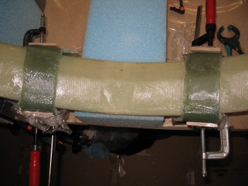
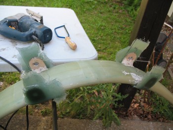
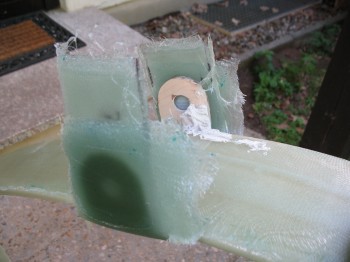
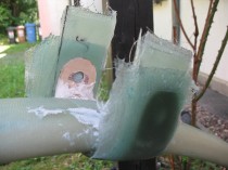
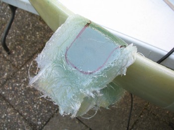
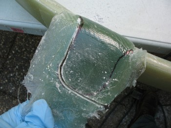
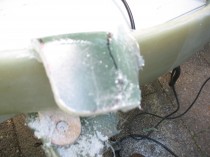
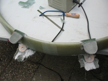
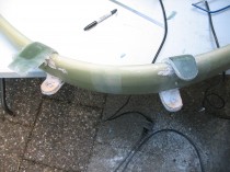
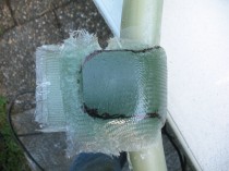
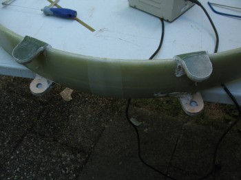
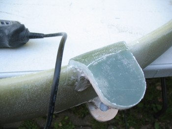
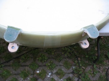
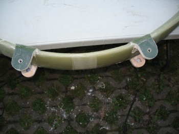
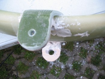
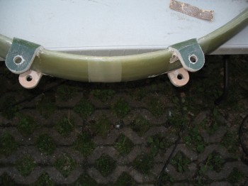
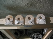
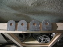
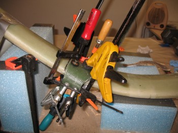
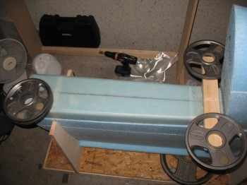
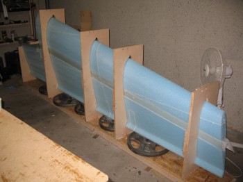 I laid up 2 sets of 3-ply BID pads directly over the previously embedded aluminum extrusions & newly glassed UNI shear web as a base for 2 more 2024 Aluminum extrusions. These 2 added extrusions were then attached & epoxied in place over the newly glassed shear web & 3-ply BID pads. The new Inboard extrusion (LWA2) was approximately the same size, while the Outboard extrusion (LWA3) was a single longer extrusion that spanned the width of the wing/shear web and covered the 2 individual/ previously embedded extrusions. To ensure the extrusions & glass coverings were securely in place, weights were added to compress the layups & squeeze out any air and/or excess epoxy.
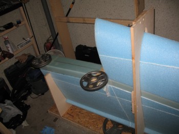
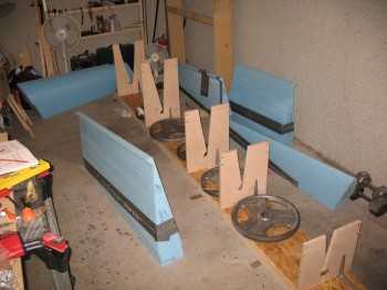
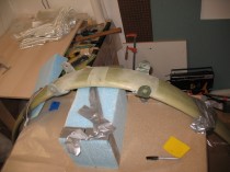
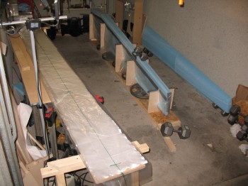
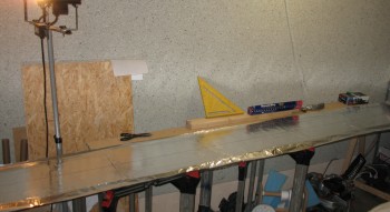
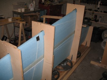
I went through and double-checked the shear web/spar cap layup, especially the edges. I ensured the peel ply was applied correctly, the weights & extrusions looked right, and the front/back (top/bottom actually) spacing between the front & rear sections of the wing were correct. Also, the spacing on the jigs looked good & the alignment was correctly maintained.

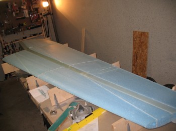
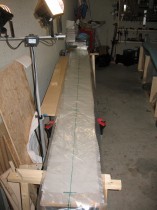
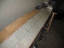
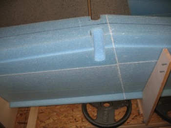
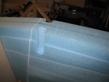
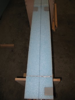
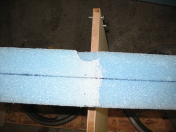
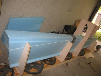
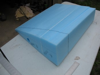
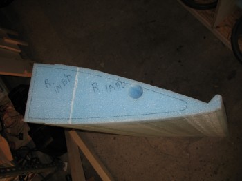
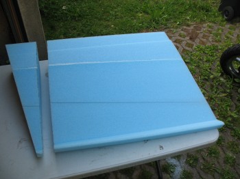
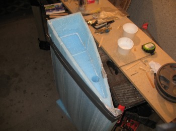
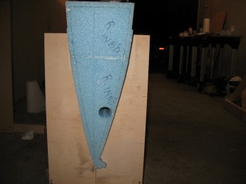
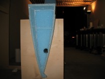
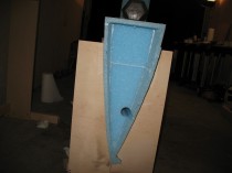
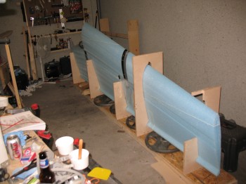
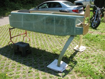
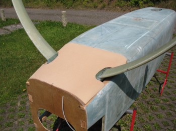
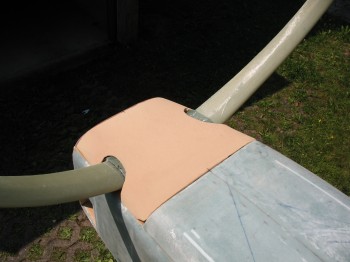
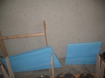
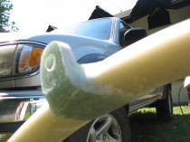
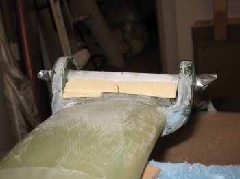
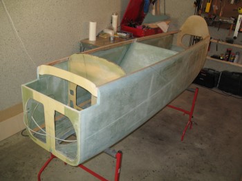
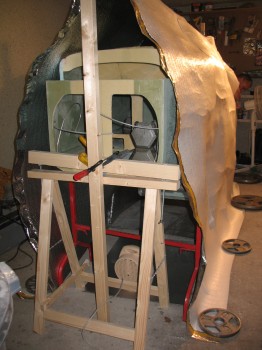
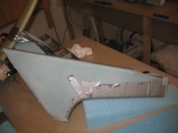
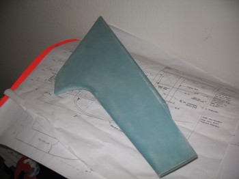
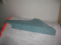
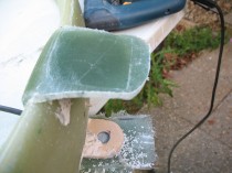
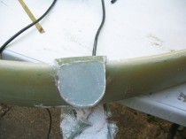
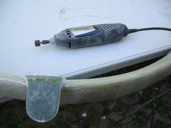
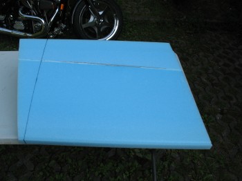 Back on the Right wing, I drew a line & cut off a wedge at the most Inboard part on the front portion of the wing. This will allow the front of the wing to align correctly with the fuselage-side strake later on after the strakes are built.
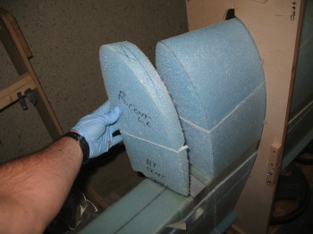
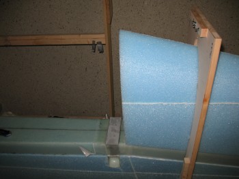
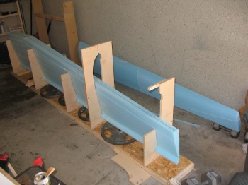
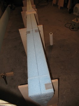
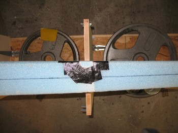
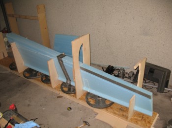
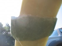
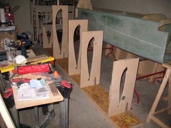
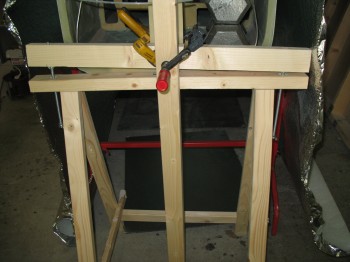
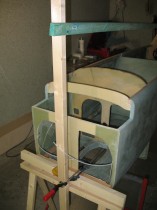
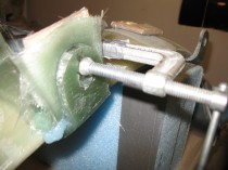
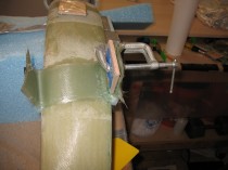
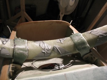
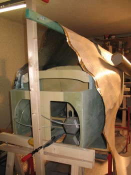
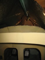
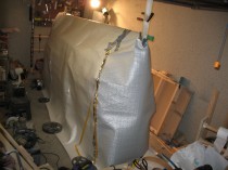
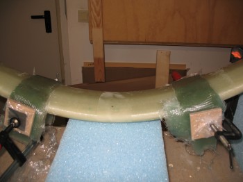
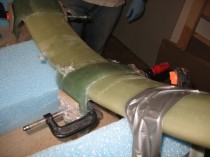
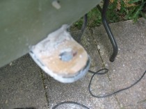
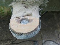
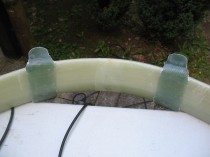
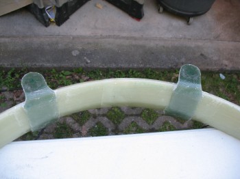
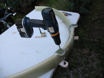
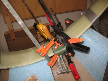
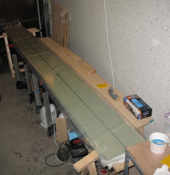
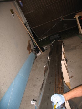
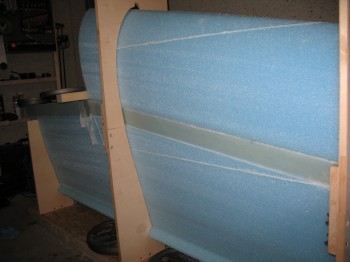
 I then whipped up some flox and floxed the jigs to the top wing surface by applying a small dab of flox every 6-12″ along the corner intersections of wing foam to wood jig (seen in the picture above).