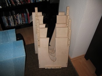
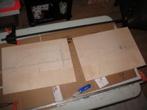
I started the day off focusing on the fuselage consoles. I cleaned up the BID tapes I glassed last night on the consoles/armrests & removed the nails holding the console tops to the sides.
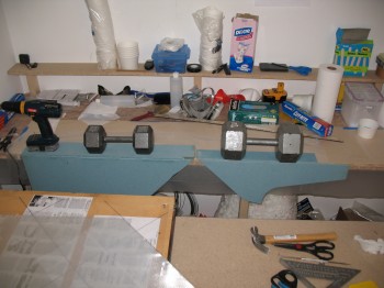
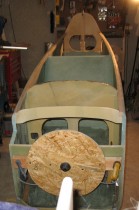
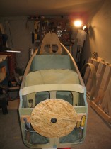
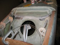
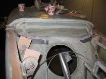
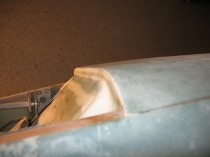
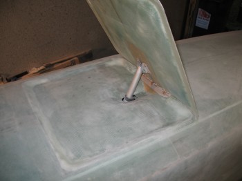
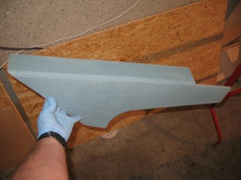
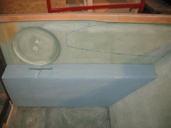
I notched the top of the left rear console (below) to prep it for an eventual install of a rear throttle quadrant. Unfortunately, when I mocked it up I completely failed to take into account the ergonomics of where the throttle quadrant SHOULD BE positioned. The positioning at the front of the arm rest is WAY too close to the GIB and needs to be much closer to the front seat. No worries! This is composites and I’ll simply fill that void in later!
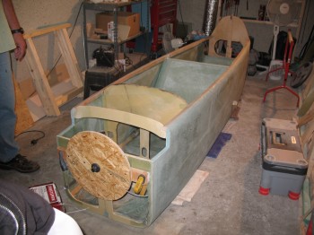
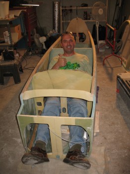
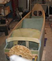
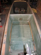
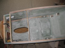
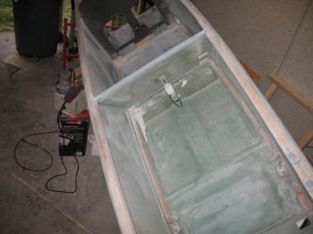
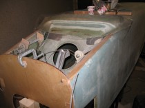
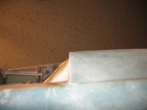
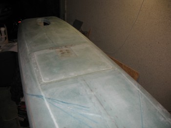
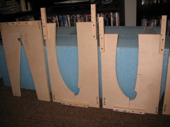
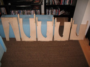
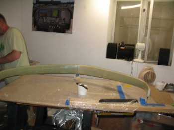
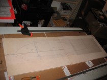
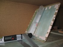
 I then took the consoles out to the garage and mocked them up in the fuselage. Again, since the fuselage side is curved and the console side edges are straight, I was just looking for the general look, fit & position of the consoles. That being said, I did take some time to shape the outer edge of the front right console & carve the depression near where the control stick area mates to the side wall/control stick depression. I then rounded over all the corner edges with a 3/8″ router bit.

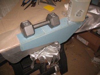
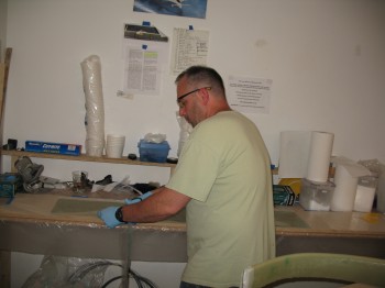
 I cleaned up any left over/excess micro and errant strands of glass on the 3 consoles. I’m waiting to build the front Left console until I nail down the mounting configuration for my throttle quadrant. The final tally on the consoles today is that the Right front & Left rear consoles are ready for exterior glass.
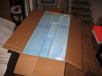
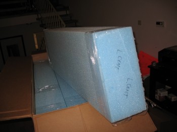
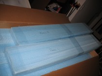
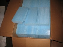
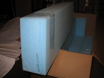
Now, the plans call for simply glassing 2 plies of BID over the entire exterior of the console and overlapping the layup onto the sidewall, fuselage floor, seats, etc. to secure it into place. Since I won’t install these before they get shipped back to the States, I want to provide the foam with a little protection. Thus, I’ll be glassing one ply of BID onto the exterior of the consoles, and then using a 2″ BID tape AND one more entire layer of BID to attach the consoles to the fuselage when I glass them in later on. It will add just a bit more weight, but then I don’t have to worry about my foam getting all dinked up in the upcoming move back stateside.
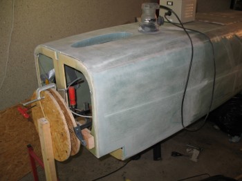
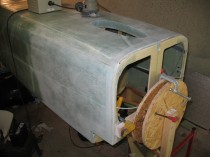
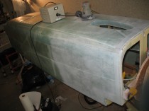
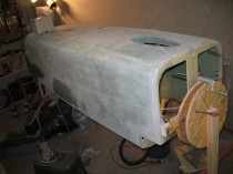
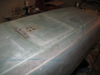
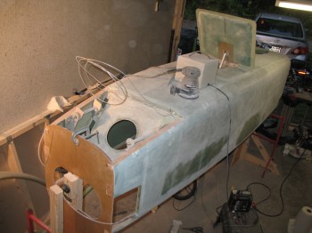
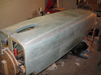
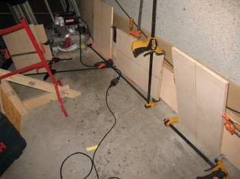
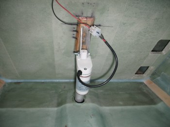
After I finished with the consoles for the day, I focused on the post cure prep for the fuselage. I’ve spelled out the details and reasonings for the post cure in a separate post today. My first task for the post cure effort was to make 2 stands that were capable of being adjusted on each corner in order to ensure that the fuselage is straight and remove any twist it may have. I cut threaded rods into 4 pieces measuring 9.75″ each. I used some 2x4s with holes drilled through each side and created a screwjack for each side of the 2×4, that will sit at the outside corners of the fuselage (sorry, no pics yet).
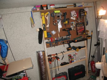
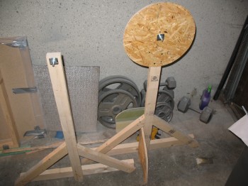
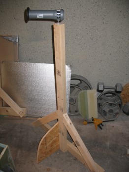
While I was at the DIY store I picked up a piece of PVC pipe to serve as my 3″ UNI tape roll dispenser for when I lay up the spar caps on the wings, CS spar and canard. I retired the spit posts and pressed one of them into service as the new 3″ UNI tape dispenser.
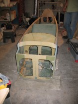
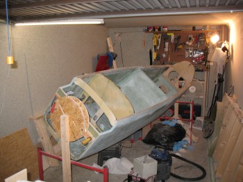
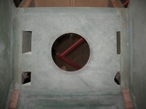
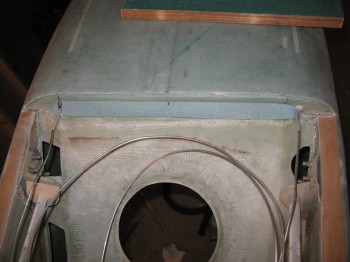
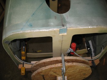
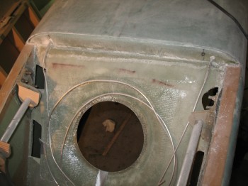
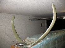
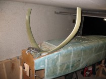
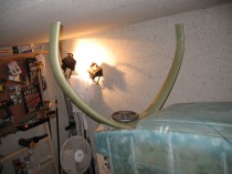
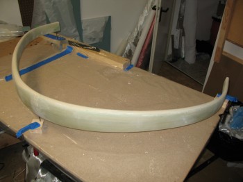
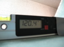
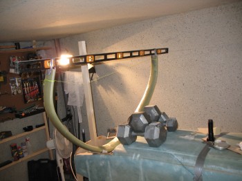
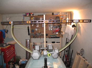
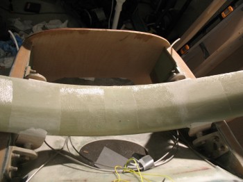
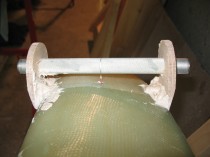
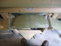
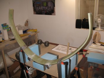
 I then turned my focus back to the main gear. I situated the fuselage back inverted and placed it on red stands. I leveled the fuselage longitudinally & laterally using weights to hold it in place. I then ensured the firewall was leveled vertically & clamped a 2×4 to it. (I had previously marked the 5/8″ OD steel gear mounting tubes (LMGAT) 0.65″ from each edge, put wood jig tabs in place, and remounted them onto the fuselage-side main gear extrusions). I put the gear in place and used an adjustable string setup to keep it upright and at the right distance from the firewall. I taped a 6′ long carpenters level to the bottom of the each gear leg, centered front-to-back so as to minimize any error. I set the gear with a 3/16″ gap between the top of the gear arch and the bottom of the fuselage longerons.
 I then set the axles’ centerline at F.S. 111.1 (stock plans is F.S. 110.5, but because I’ll be mounting a heavier IO-320 engine and some discrepancies I see in the plans, I’ll be moving the axle positions back about 1/2″ . . . [Ed. See my buddy Marco’s in-depth discussion on this at longezproject.blogspot.com… he explains it all nicely])
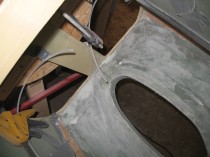
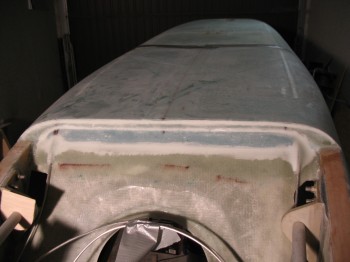
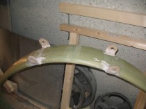
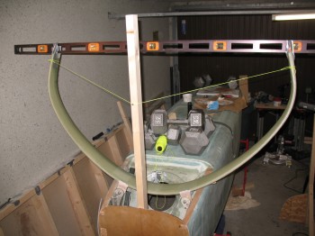 After spending an hour or so ensuring that everything was lined up, straight, square… and that the measurements were as spot-on as possible, I bondo’d the wood jigs (that were pre-installed on the fuselage) to the main gear bow.
 After the bondo cured for a bit, I trimmed the excess off & cleaned it up, and then left it alone to dry overnight.

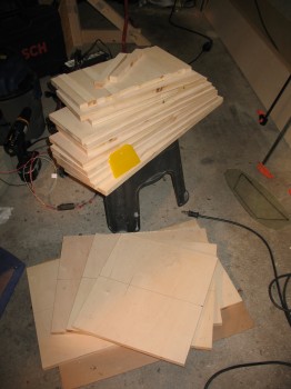
 I then went on a foraging mission for materials at Praktiker & Toom (German DIY stores).
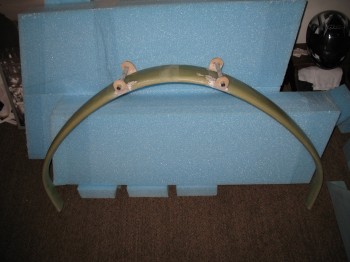
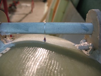
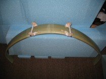
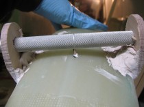

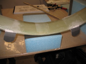
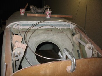
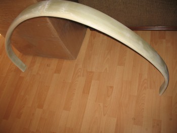
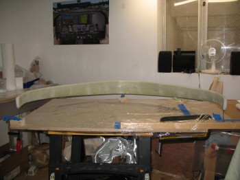
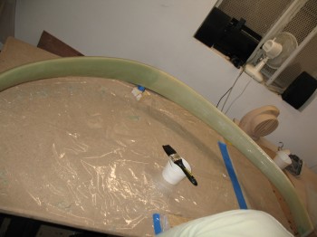
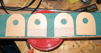
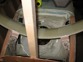
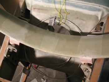
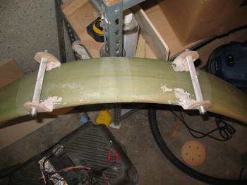
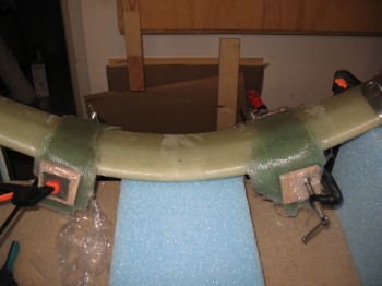
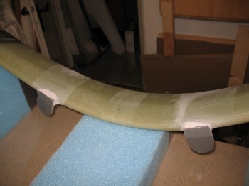 I then glassed 2-1/2″ x 12″ 18-ply UNI strips onto the bottom of the gear on each side. These long UNI strips start & cover the tab on one side, then get laid across the gear strut and end by covering the other tab. Analogous to a UNI “band” or “strap” across the bottom of the gear bow, for the left and right side mount. Once the 18-plies of UNI are in place, then on each tab, placed over the now pre-existing UNI band, 18 plies of 2-1/2″ x 2-1/2″ BID squares are glassed onto each tab (only covering where the gray duct tape was applied). So, total glass each side: 18-plies of UNI (side-to-side strap) + 18 + 18 = 36 plies BID (tabs only). I then clamped 2-1/2″ x 2-1/2″ wood pieces covered in saran wrap (so they wouldn’t stick to the layup) over the outside plies of BID with just enough pressure to squeeze out any excess epoxy and to form a nice smooth/straight outer surface.
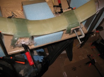
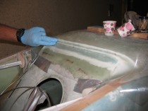
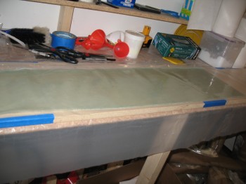
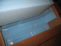
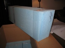
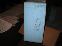
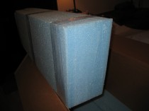
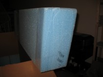
 After a break, I glassed the Right front and Left rear console with 1-ply of BID and peel plied.