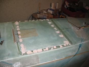
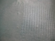
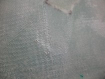
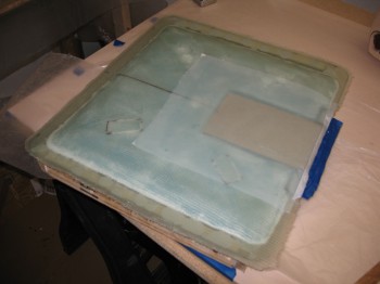
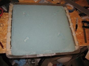
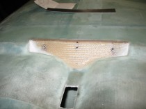
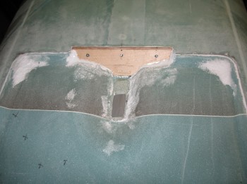
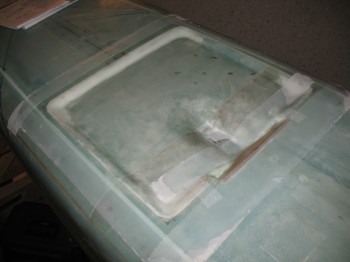
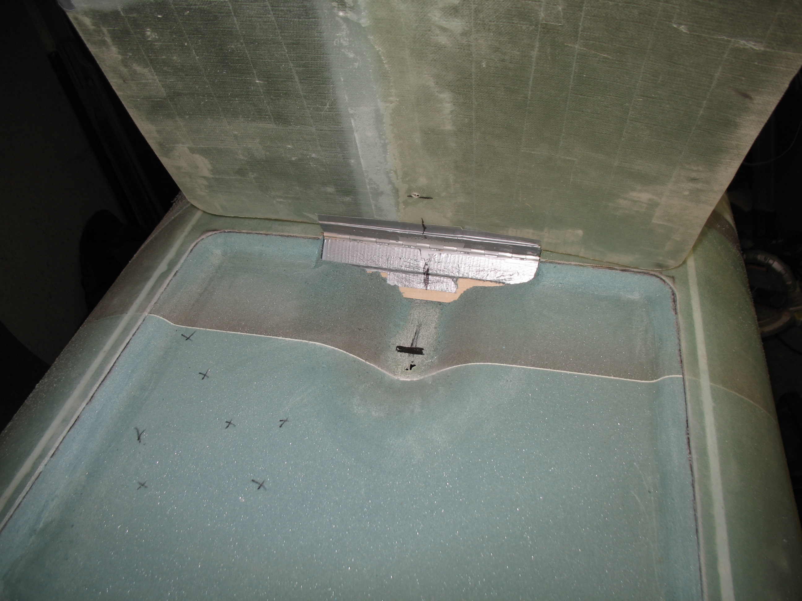
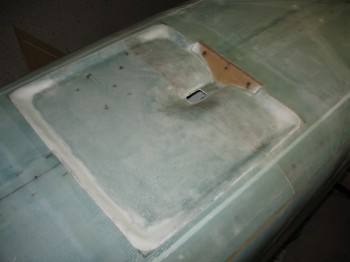
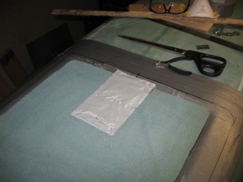
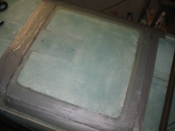
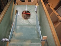
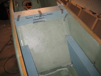
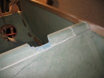
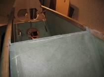
I checked the landing brake depression layup and it looked good! I forgot to mention that before I glassed the depression area, I covered the 3 each ~1/32″ holes in the center of the bolt hole markings–on the OUTSIDE/UP-SIDE of LB23–with a small piece of duct tape to keep any epoxy out. You should be able to make out the small pieces of silver tape under the glass in the pics below.
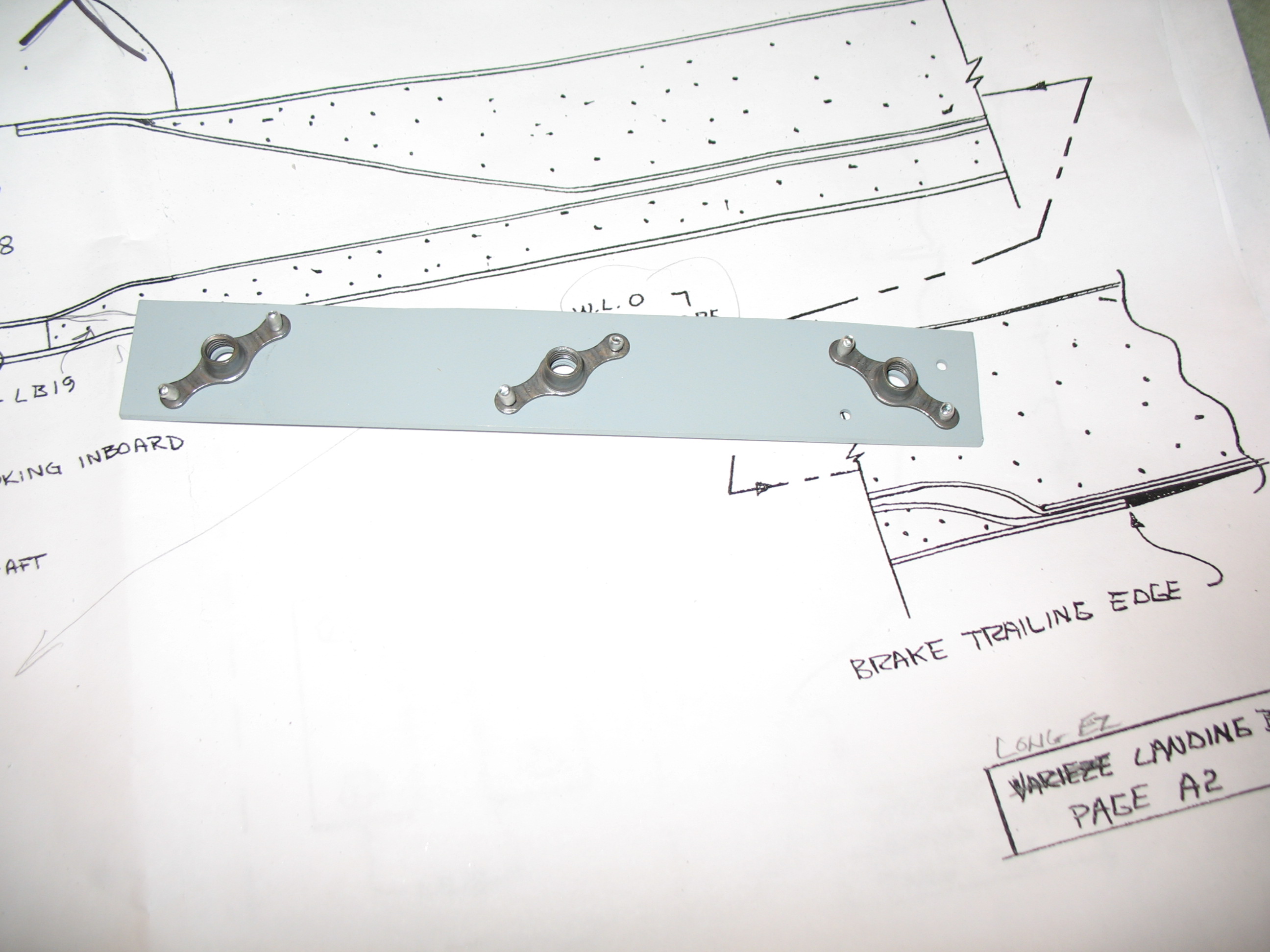
As I’ve mentioned before, with the MGS-285 system you get a very clear cure, so you can see everything underneath… kind of like an animal with see-thru skin. Sometimes looking at other builds where AeroPoxy, EZPoxy, etc. was used it makes it seem more “finished” since you can’t really see through the glass structure and the layers are quite opaque. Conversely, quite often the x-ray vision that MGS provides makes it easy to locate buried “treasures” under the skin… of course my 3 landing brake hinge bolt locations being what I’m on about here. Thus, being able to clearly see my 3 Sharpie targets allowed me to quickly drill my 1/4″ bolt holes through the 3 plies of BID and a very thin layer of Birch plywood (remember: 95% of the depth of each hole in the plywood–sitting in-place over each nutplate–was pre-drilled).
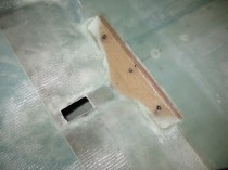
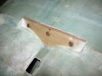
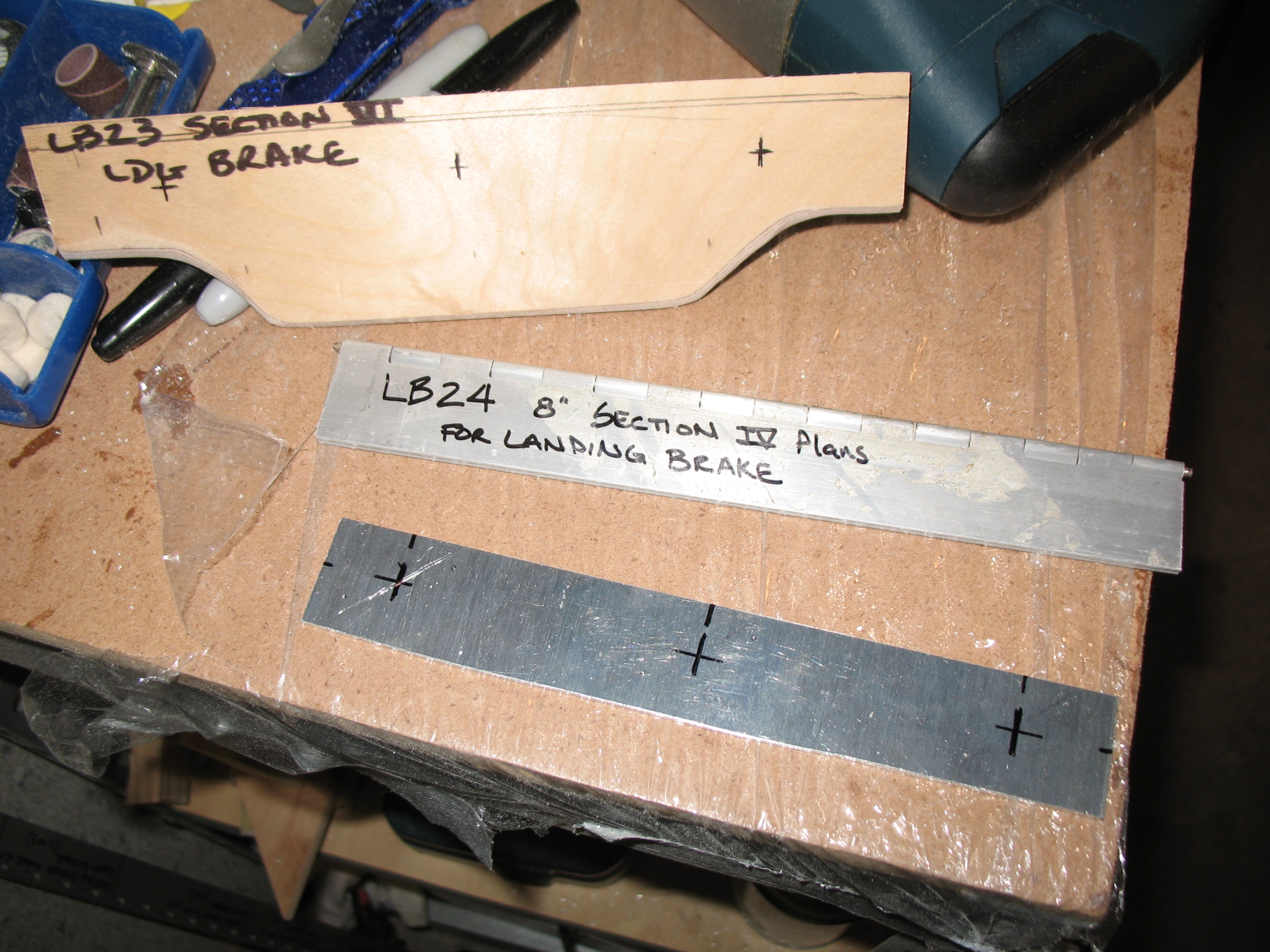
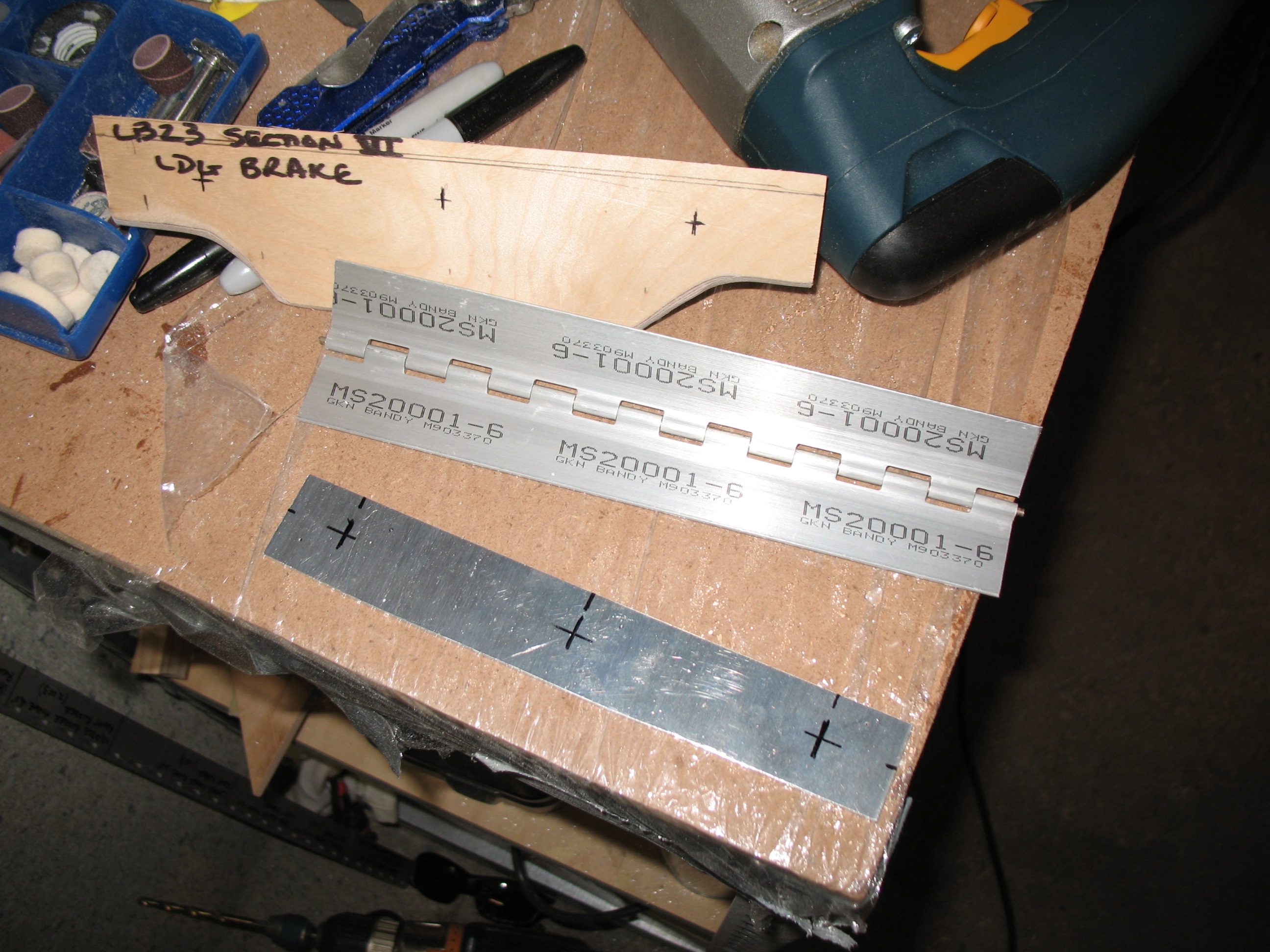
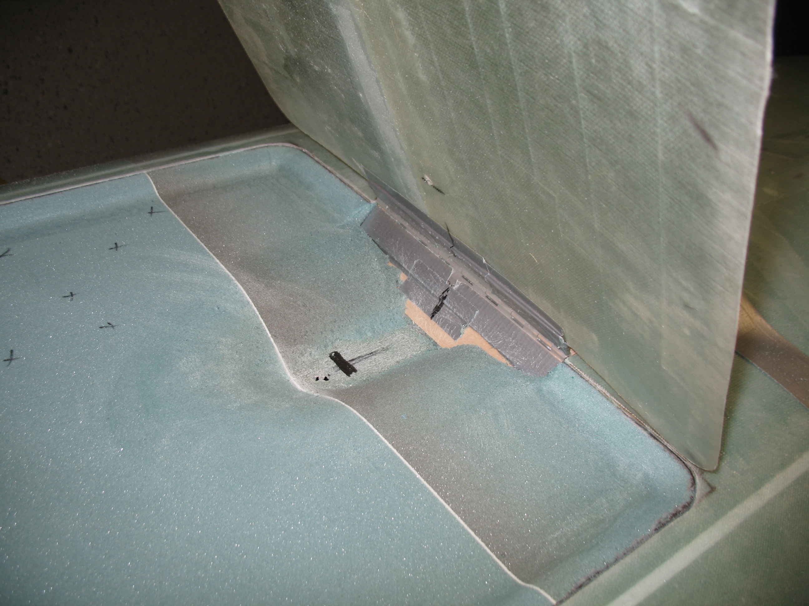
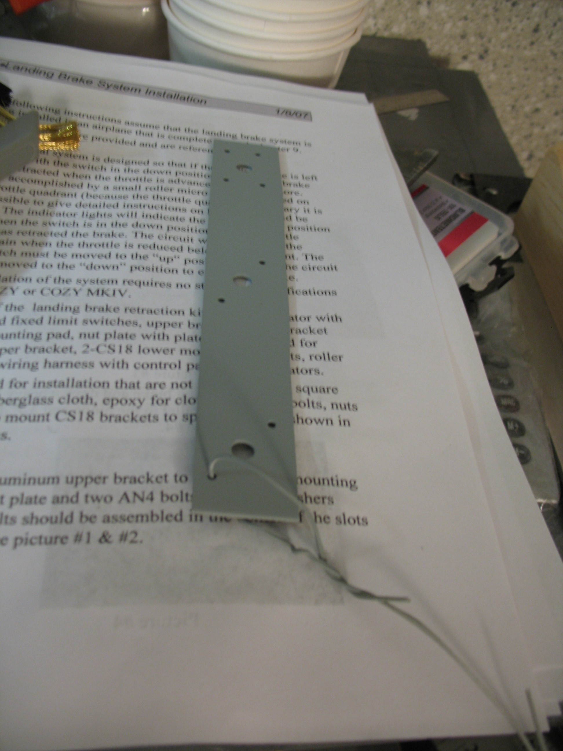
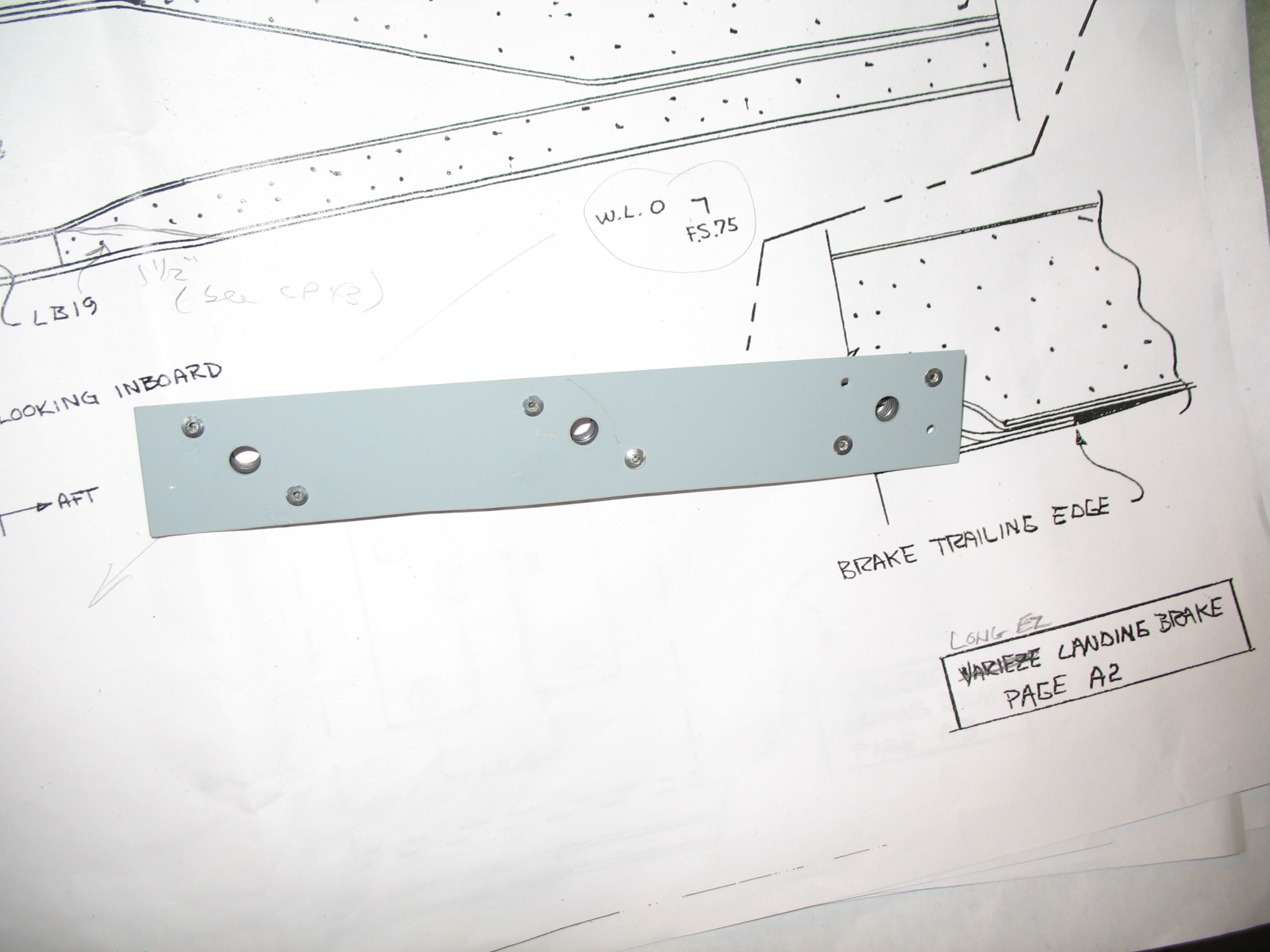
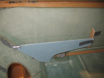
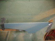
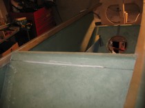
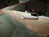
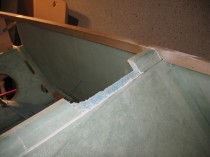
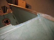
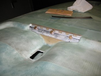 I sanded the edges of the glass in and around LB23. I had to really get in the corners to make it so I could get the hinge mounted in there, or so I thought. I have to admit, since I hadn’t really seen a lot of pics/depictions of this install, I realized that I was winging it to a degree and that I was in some what uncharted territory. After sanding the corner insets just in front of LB23, I set out to fit in the hinge. This required removing some of the upper edge of the hinge (lower as the pictures are oriented since the fuselage is inverted). I ended Dremeling about a 3/16″ radius off of each corner of the hinge. Once I got the hinge set, I mocked up the hinge fit and started the bolts to make sure they would fit, which they did. All looked good, except one thing . . .
I realized after the bolts were in, that I probably should have adjusted for the angle at which the hinge sits in comparison to where the bolts are positioned. With the bolts along a line centered from top-to-bottom of the hinge, once the hinge is tilted back, it brings the head of the bolt up closer to the actual hinge point. So, even the bolt shanks are actually center-of-mass on the hinge, the bolt heads look like they are positioned just a tad too high. I considered trying to fix this, but then what would it really effect? I figured apathy would probably be the best course of action here: Oh well, if it works it was “done correctly” (Snark alert!)
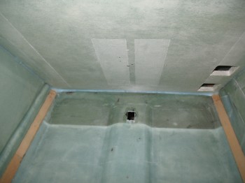
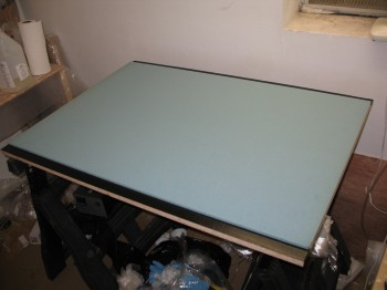
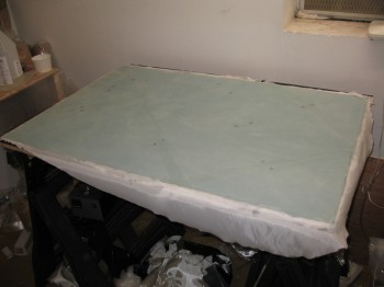
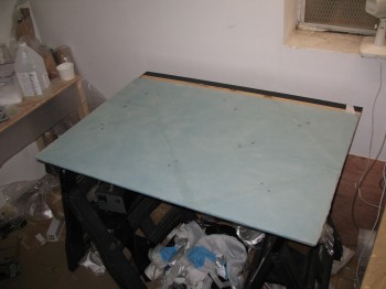
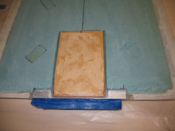
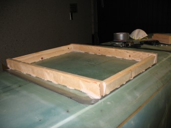
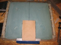
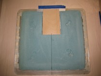
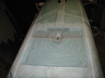
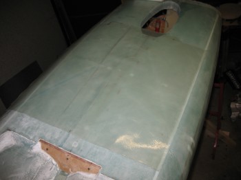
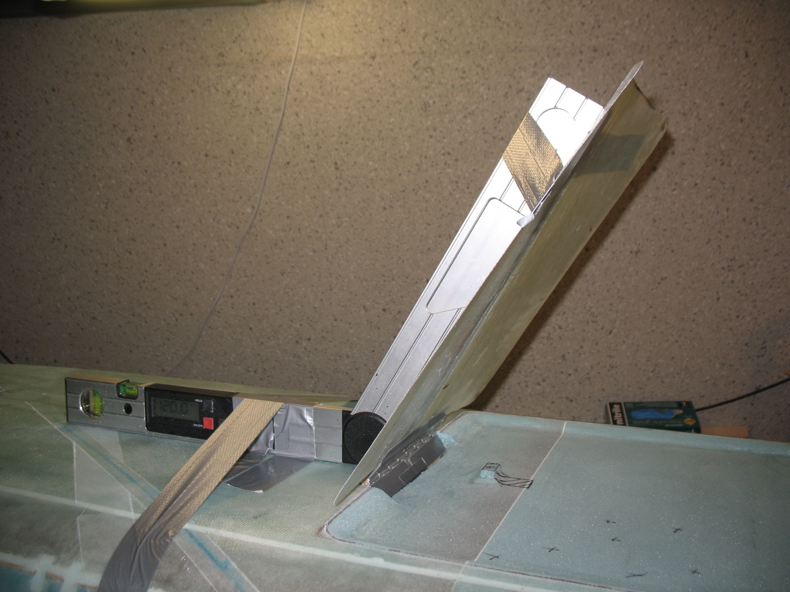
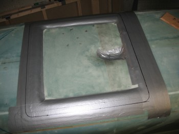
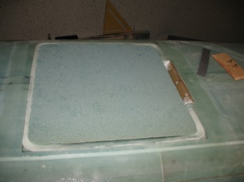
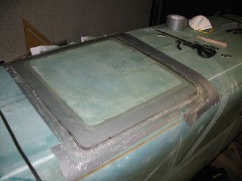
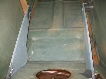
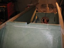
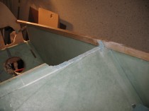
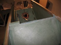
Next, it was time to start prepping for the actual landing brake construction. To start, I taped up the fuselage edge all around the landing brake outline with 2 plies of duct tape.
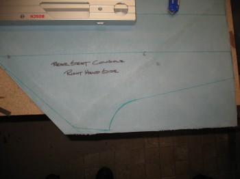
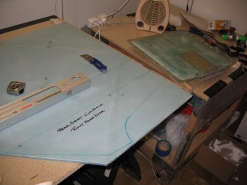
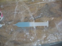
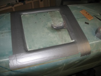 I then, once again, grabbed the glass piece that I originally cut out of fuselage to use as an outline template for the landing brake ‘door.’ I marked the outline with a black Sharpie.
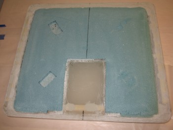
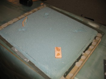
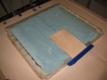
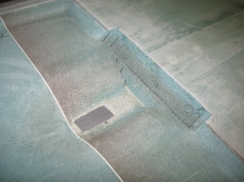
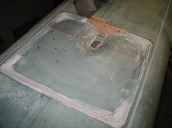
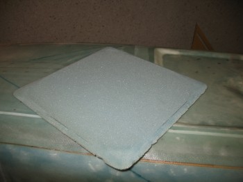
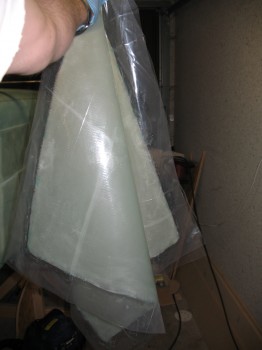
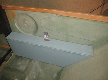
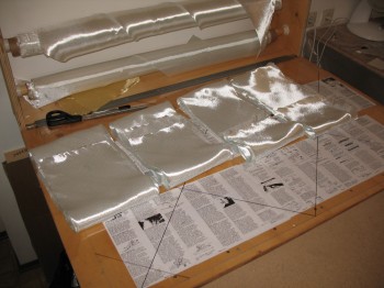
 So, there comes a time, in retrospect, that you do something in an attempt to conserve resources that ended up making the job a lot more difficult. Well, this next step was one of those scenarios. I mentioned previously that I had tried a lo-vac layup with some lightweight fiberglass cloth that went south in a fairly ugly manner. I was able to easily rip the cloth off the foam once it cured, so I was left with a decent amount of 3/8″ foam with a thin layer of epoxy on it. Well, I’m cheap… I didn’t want to order more foam and have it shipped to Germany, so I figured I would use it. It worked, but to quote an oft-used Bob Nuckolls phrase, it was not “an elegant solution.” Thus, the black squiggly lines you see on the foam are the leftover Sharpie marks depicting some of the remaining epoxy remnants, after I shaped it of course.
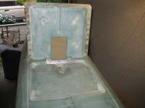
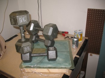
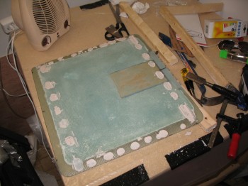
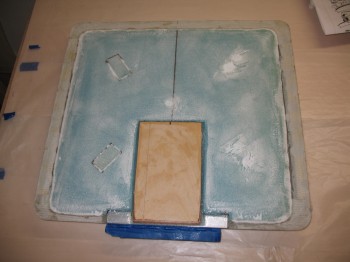
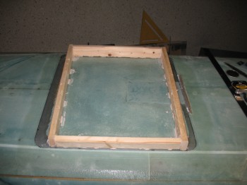
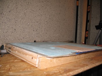
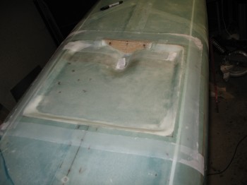
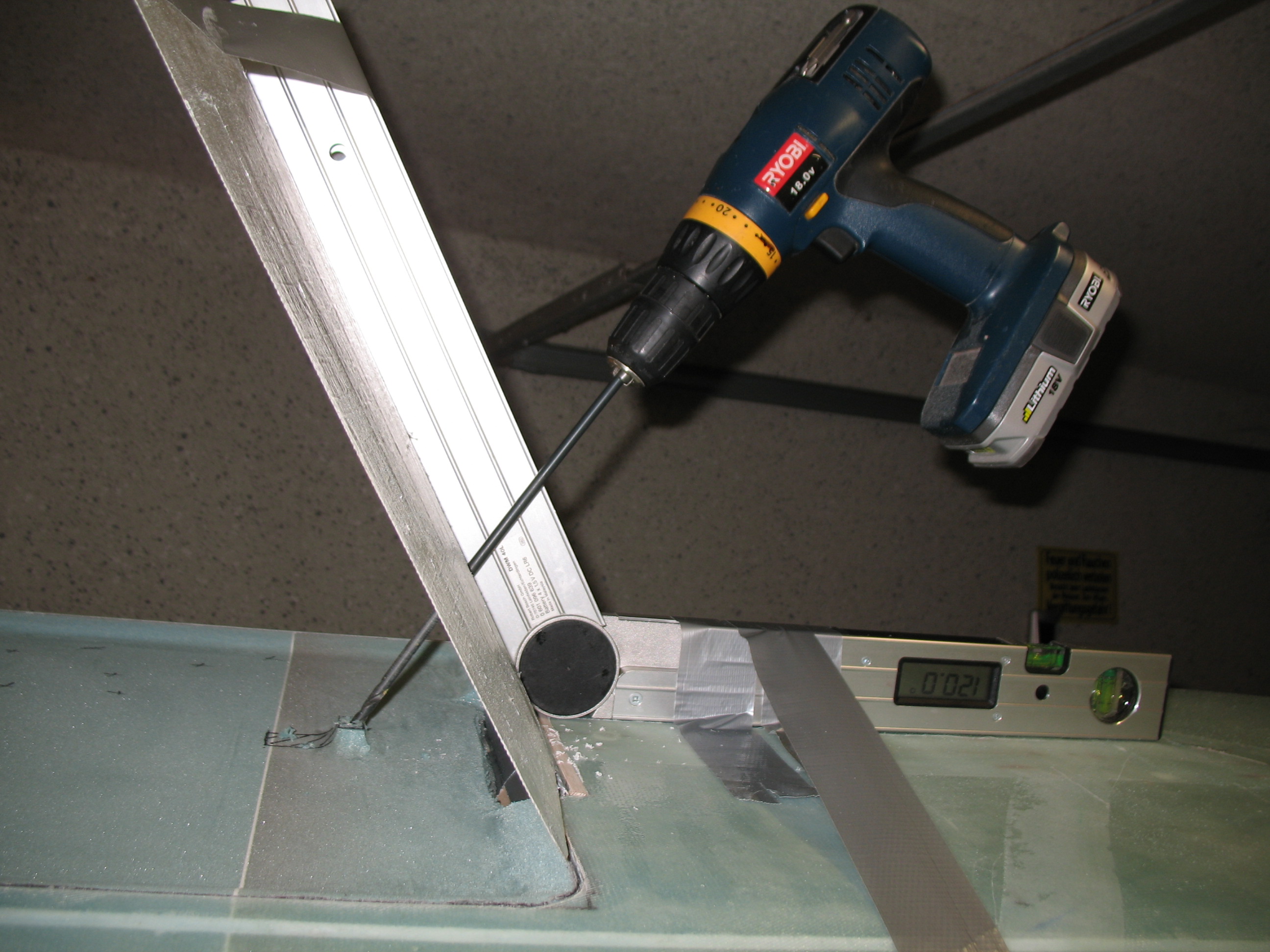
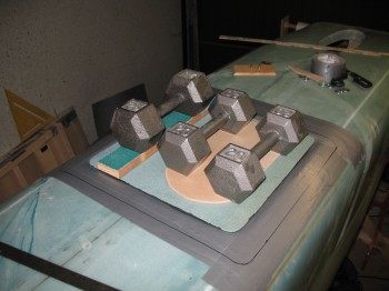
 I cut ~0.2″ wood spacers from a 2×4 & 5-min epoxied them to the inside of the landing brake depression on the fuselage side and to the landing brake foam. I then threw some weights on top of the landing brake to ensure it all cured in the correct position.
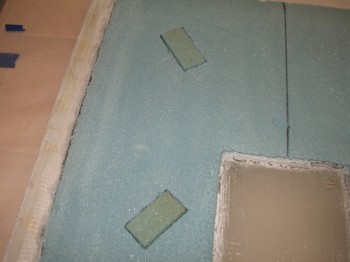
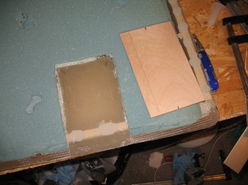
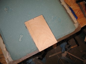
I then cut LB19–the center 1/4″ Birch plywood–reinforcement piece that gets embedded into the center of the landing brake ‘door’ (adjacent to the hinge) to provide the hinge a solid mounting point. I made LB19 a tad bit bigger than plans, since I was using slightly thinner foam (I crosschecked the use of 3/8″ foam with a couple of old-hat builders) for my landing brake. My final LB19 dimensions came out to be 7.7″ x 4.5″.
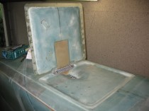
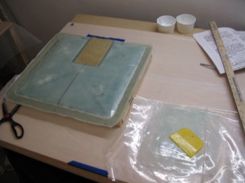
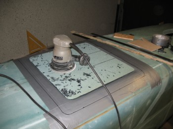
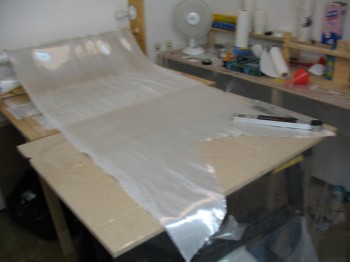
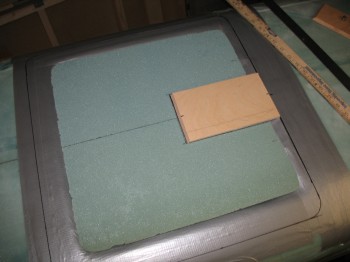 Once my LB19 was cut & beveled on one end, I laid it out on top of the landing brake foam and traced the outline. Next, I sanded off the excess epoxy crap off the “top” of the landing brake, and then, thinking I would make it a little easier on myself, I decide I would throw some peel ply under the glass layup of the landing brake’s outer skin. This way when I went to flox LB19 to the outer glass, the glass texture would be already prepared and the amount of sanding much reduced (it worked to a fair degree). I pinned the peel ply in place using standard staples.
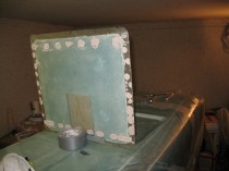
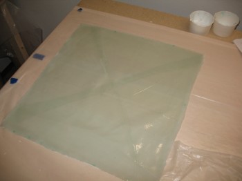
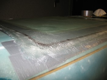
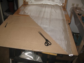
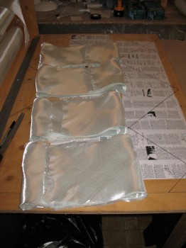
 I went inside to my downstairs lair and prepared a 3-ply BID “Poor Man’s” pre-preg setup and wetted it out. I took it out to the garage and set it aside for a little bit while I micro-slurried the “top” of the landing brake foam. I laid up the 3-ply pre-preg ensuring that I got all 3 plies over each of the black landing brake border outline. I waited a few hours until the layup got tacky, and then I knife-trimmed the edge at 1-1/2″. After reviewing my build notes I realized about an hour later that I was only supposed to leave about a 1/2″ edge, so I knife trimmed 3 sides down to a 1/2″ overlap, and on the hinge side cut it down to 0.35″ overlap for clearance.

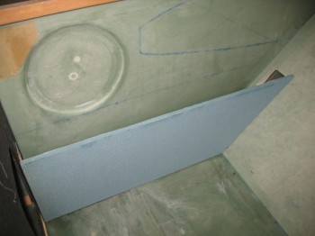
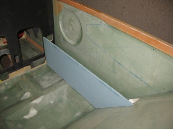
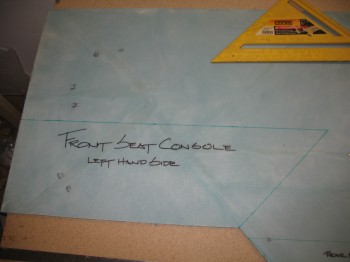
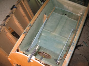
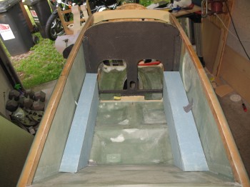
 I mocked up the sides of both front seat consoles.
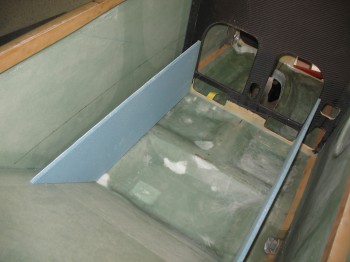
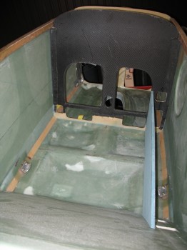
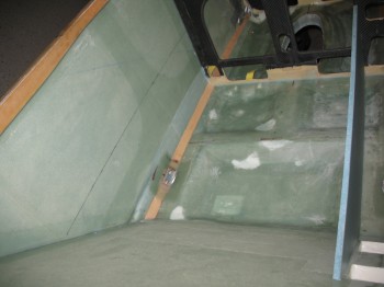
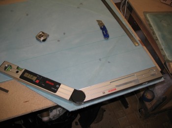
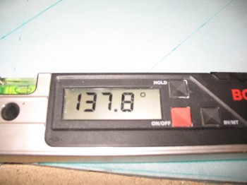
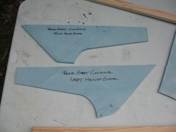
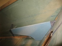
 Then I turned my attention to the rear seat consoles. It took a little bit of time fine tuning the angles, mainly between the rear seat back and console junction.
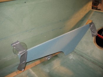
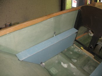
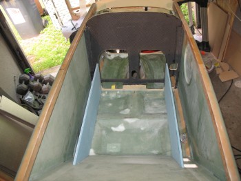
 The front console sides are wedged in nice and tight, so mocking up the tops are no problem. However, the rear consoles are jury-rigged in place with tape, so even though I did a cursory check, I didn’t mock them up like I did the front… or take any pics.
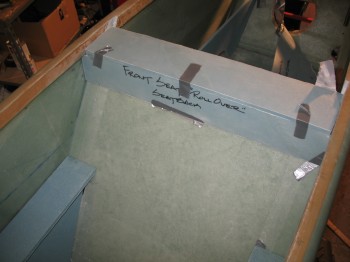
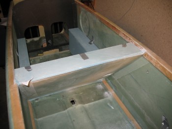
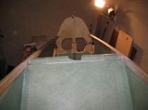
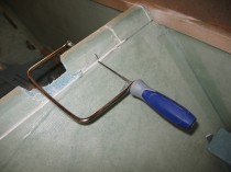
 After playing around with the front seat top cap (“rollover” structure base), I realized that no matter what, the front seat was going to be too high. It needed to come down at least 1.0″. A few more times looking at it and trying out different variants of a top-of-the-seat structure definitely convinced me that the seat back needed to be shortened, so I broke out the battery powered Skilsaw and a coping saw.
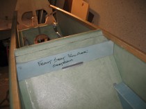
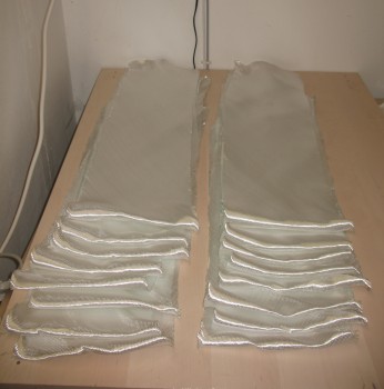
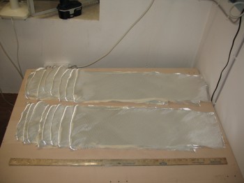
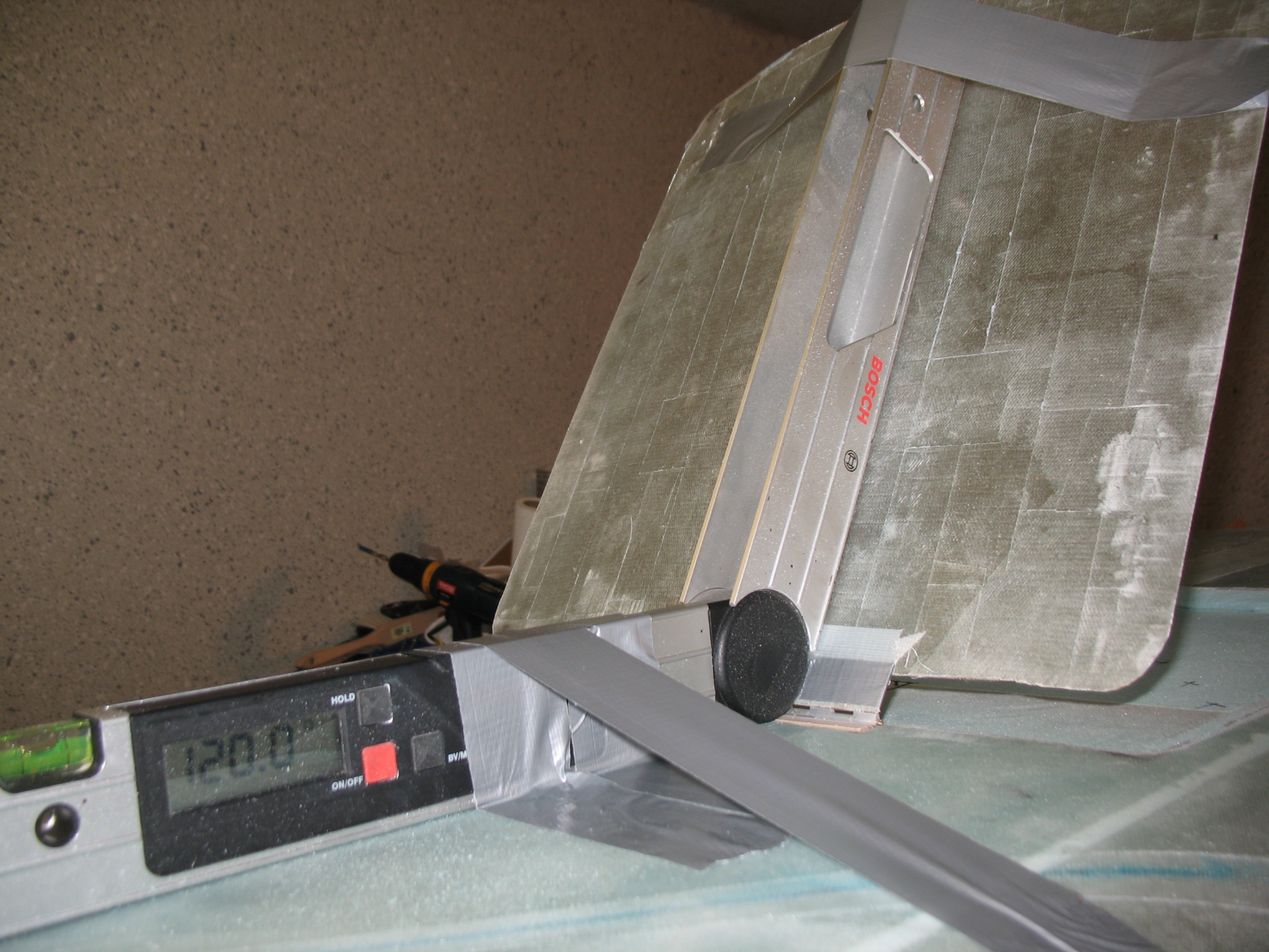
 The final tally is 4 sets of 4 each UNI strips, 9″ wide at 30-40°.