
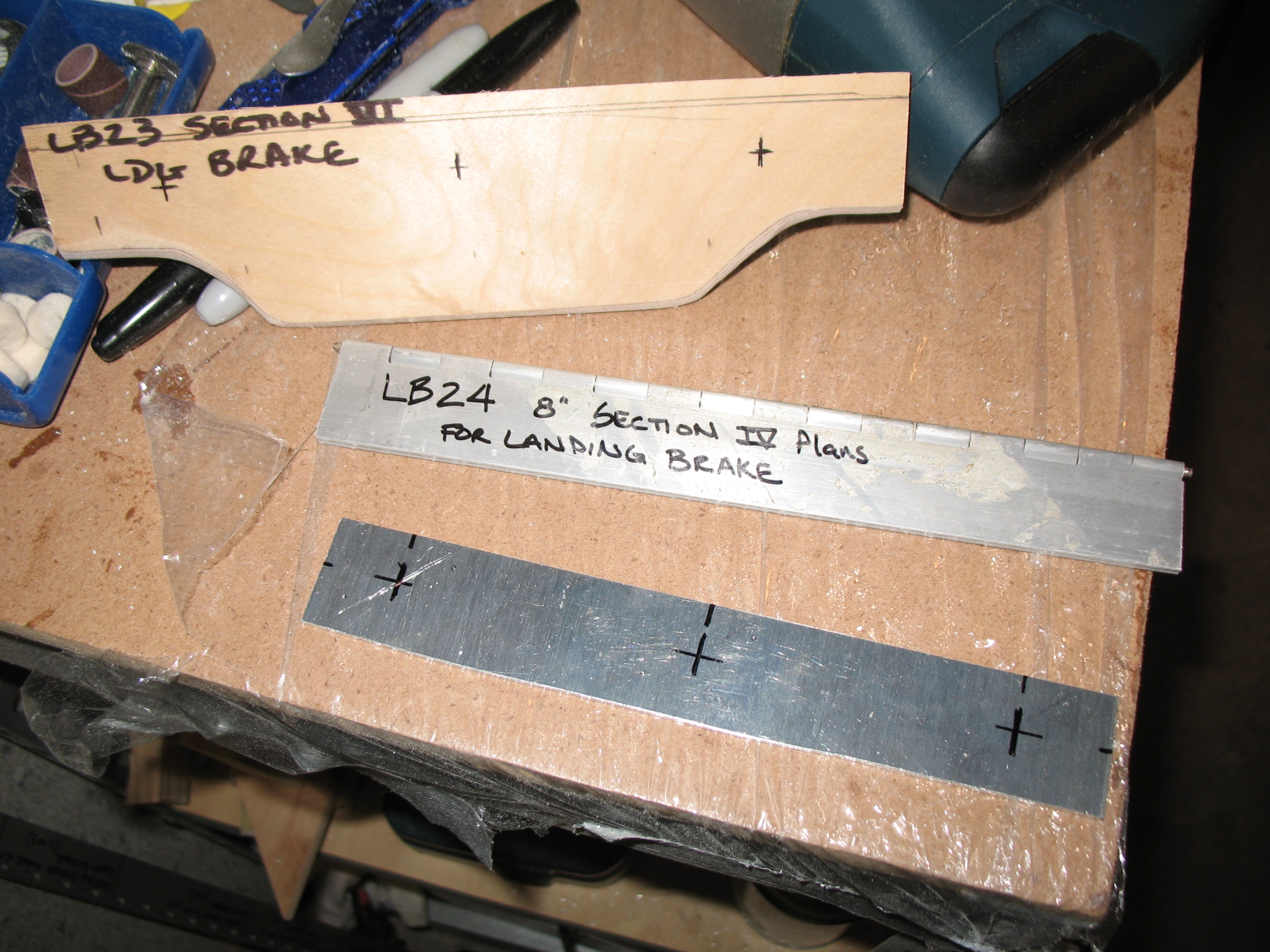
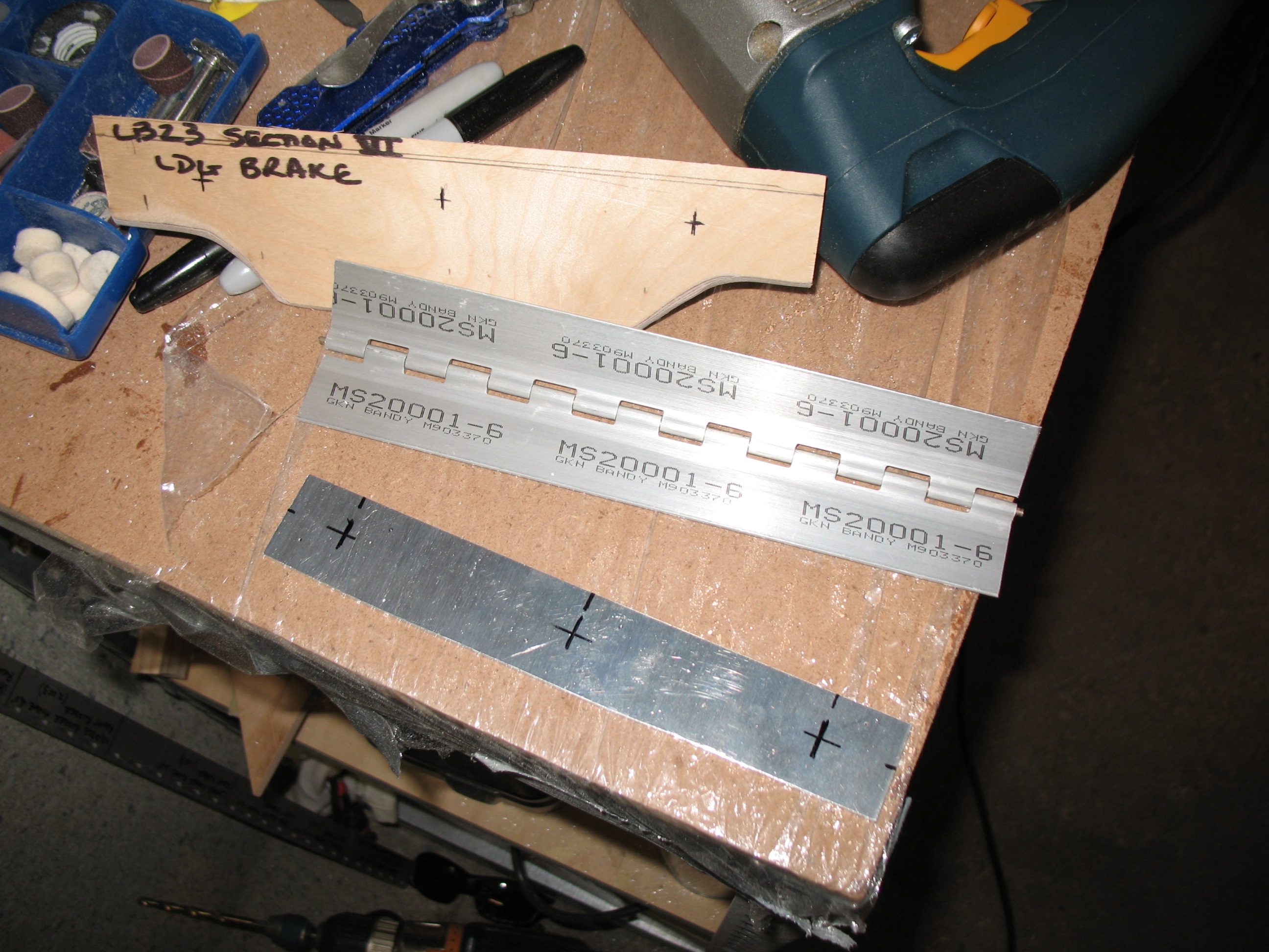
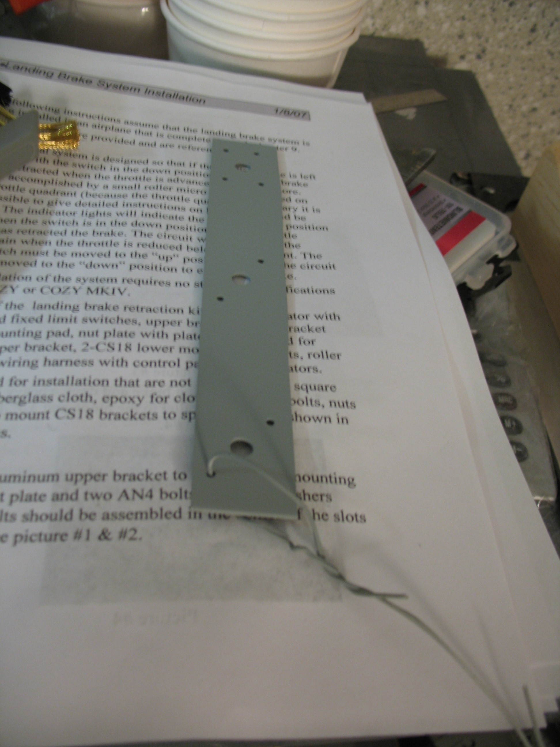
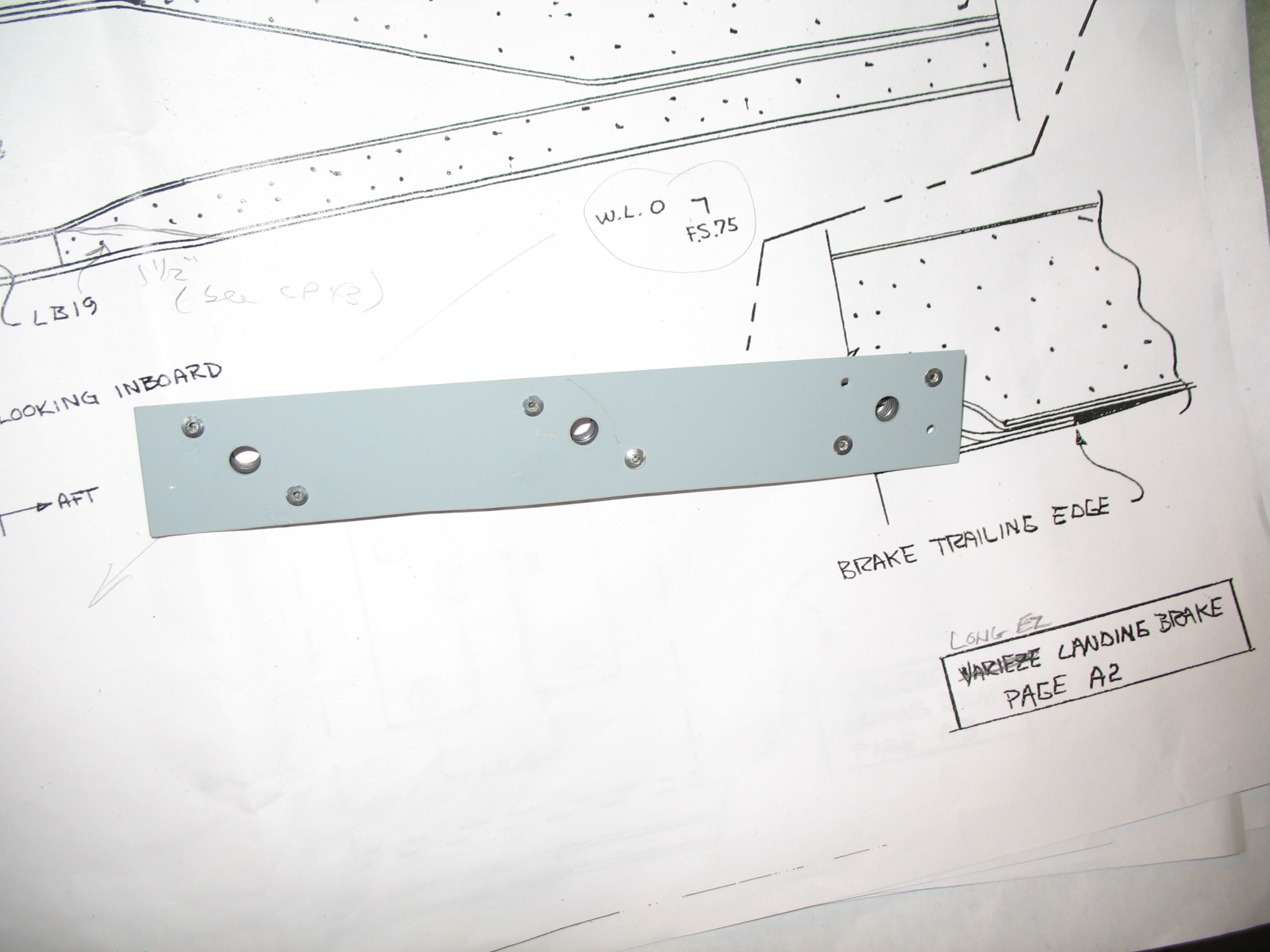
Well, being a noob I decided NOT to use the 0.5mm anodized aluminum and went with 0.063″ 2024T3 aluminum instead as a plate to secure the nutplates behind the LB23 hard point. I wasn’t sure if the .5mm aluminum was robust enough for the task and the time difference wasn’t favorably to using my “call a friend” option, so I accepted the extra ounce of weight and pressed on.
I cut the aluminum into a 1.1″ x 8.0″ piece, marked the 1/4″ bolt holes and the 1/8″ rivet hole positions for the K1000-4 nutplates. I drilled the 6 ea 1/8″ holes first then I drilled the 3 ea 1/4″ holes. On one end the 1/8″ rivet holes didn’t line up just right, so I flipped the nut plate on the opposite angle and re-drilled.
 I chamfered all the holes and then prepped the aluminum plate for primer by washing it with simple green (amazing stuff) and 60 grit 3M pads. Once it was dry, I hung it on a wire and rattle-can primed it with Rustoleum. [You may be asking why I didn’t Alodine the 2024T3? Well, I was trying to. I had alodine and alum-prep… IN THE STATES! Which of course I couldn’t ship over to Germany. And as hard as I tried (via Aircraft Spruce.EU… great folks!) I could only get aluma-prep, but not Alodine. I tried everything I could think of, but try a Google search in German! I did however eventually get the Alodine as well.]

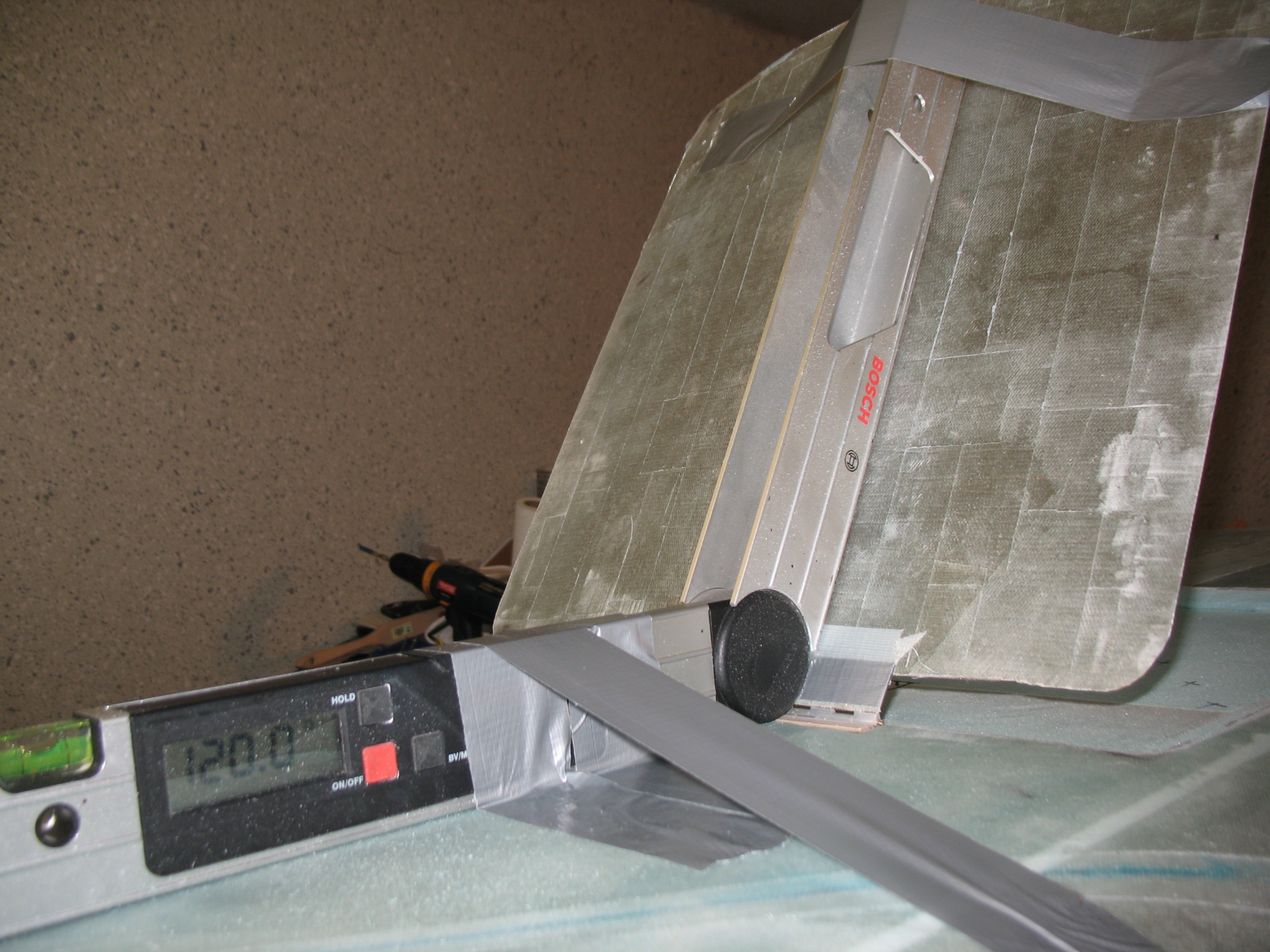
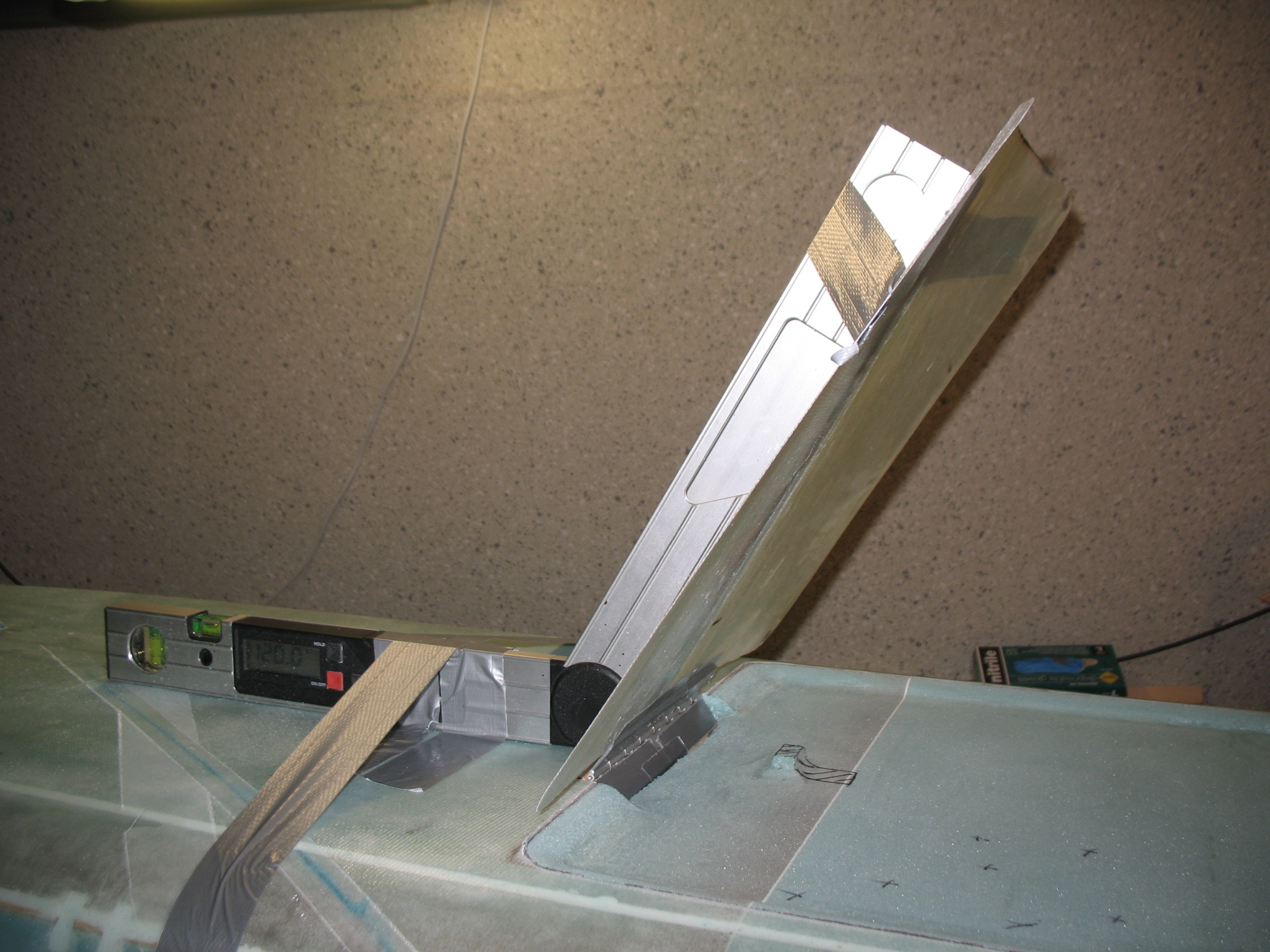
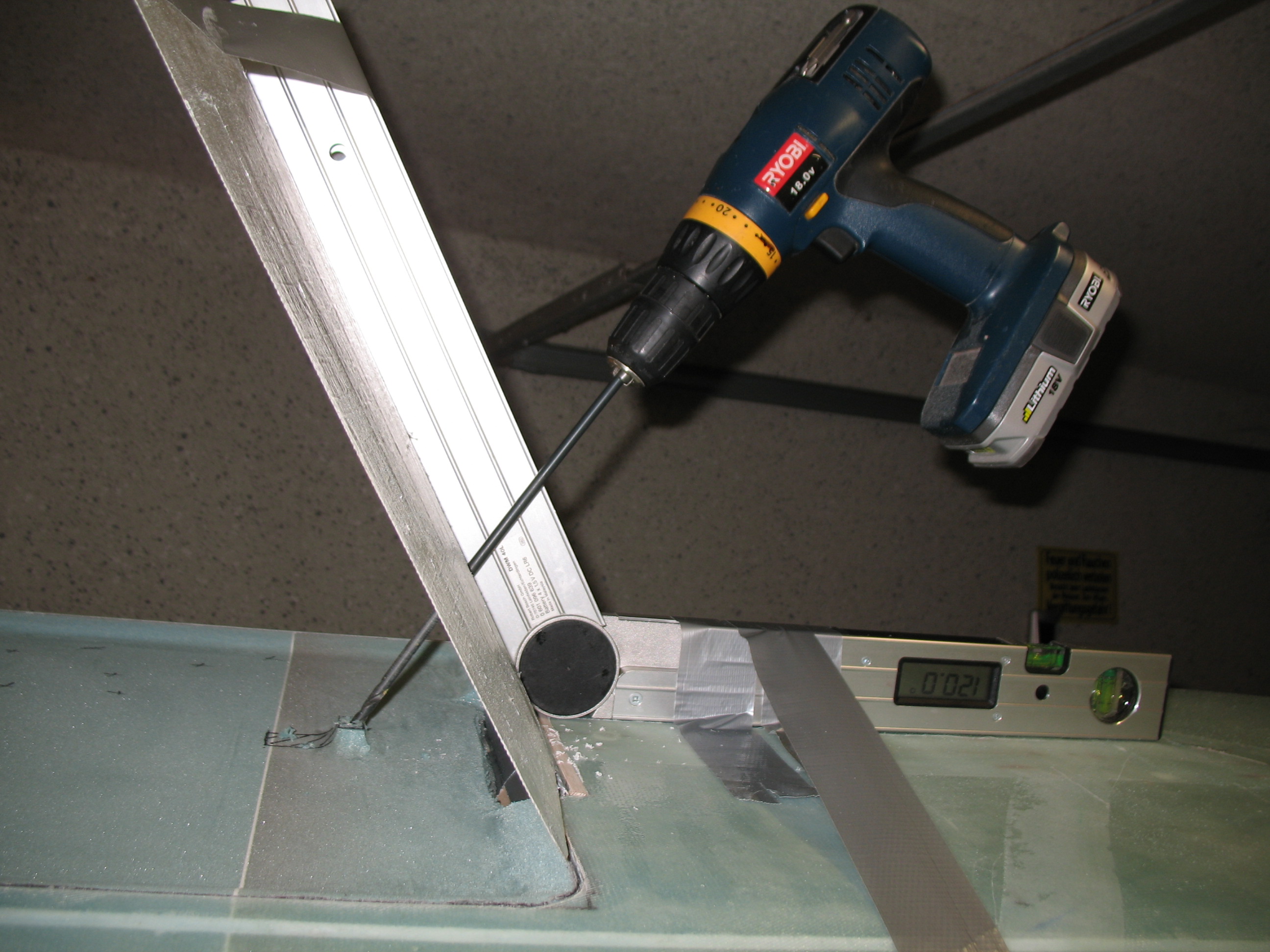
While the primer dried I mocked up LB23 and temporarily attached the hinge using duct tape. I used the landing brake fuselage glass outline, that I removed initially, as the landing brake door. I set it at the required 60° angle (the digital square shows 120°, since to get 60° you have to subtract it from 180°: 180 – 60 = 120). Now that was EZ!
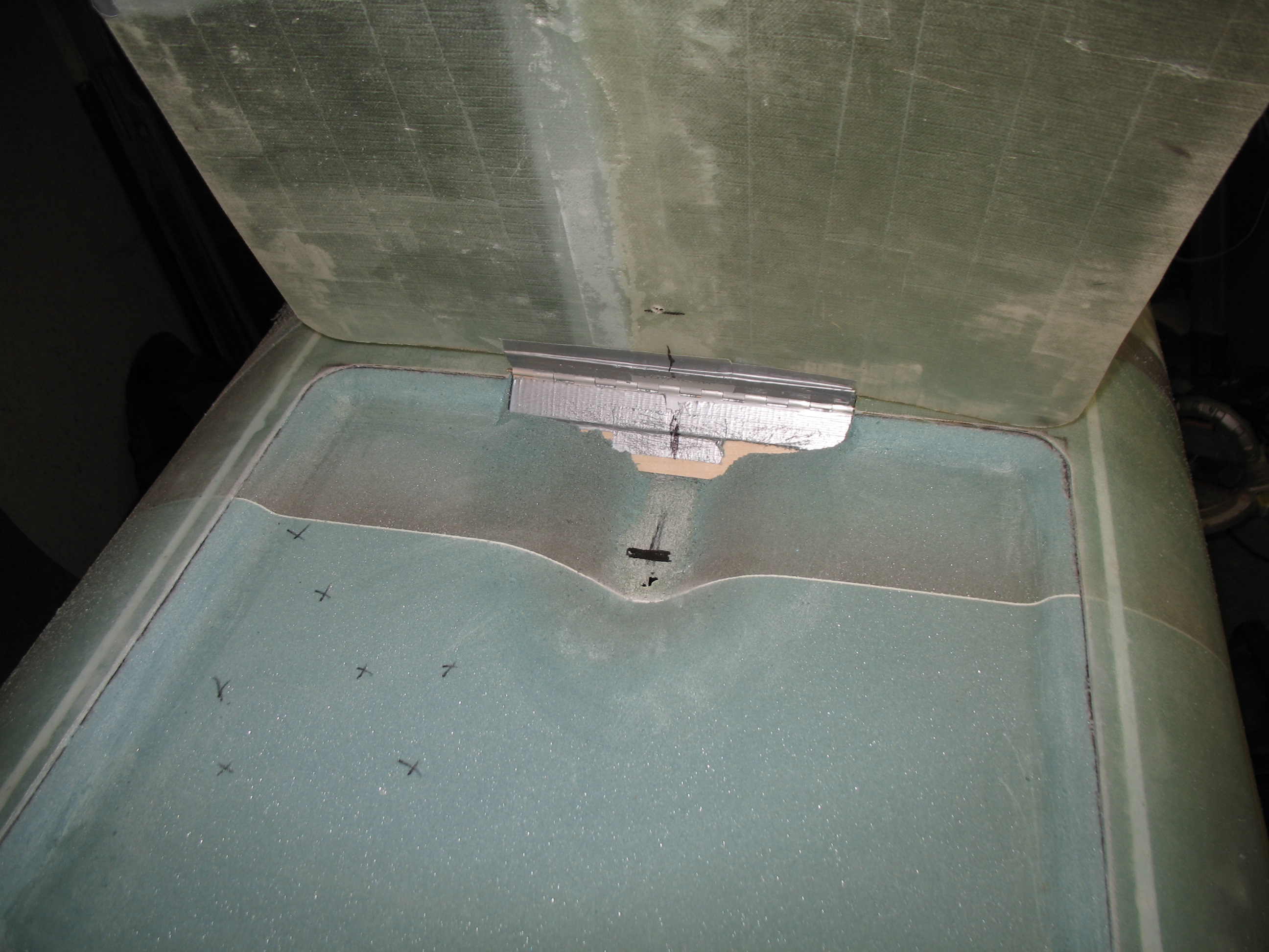
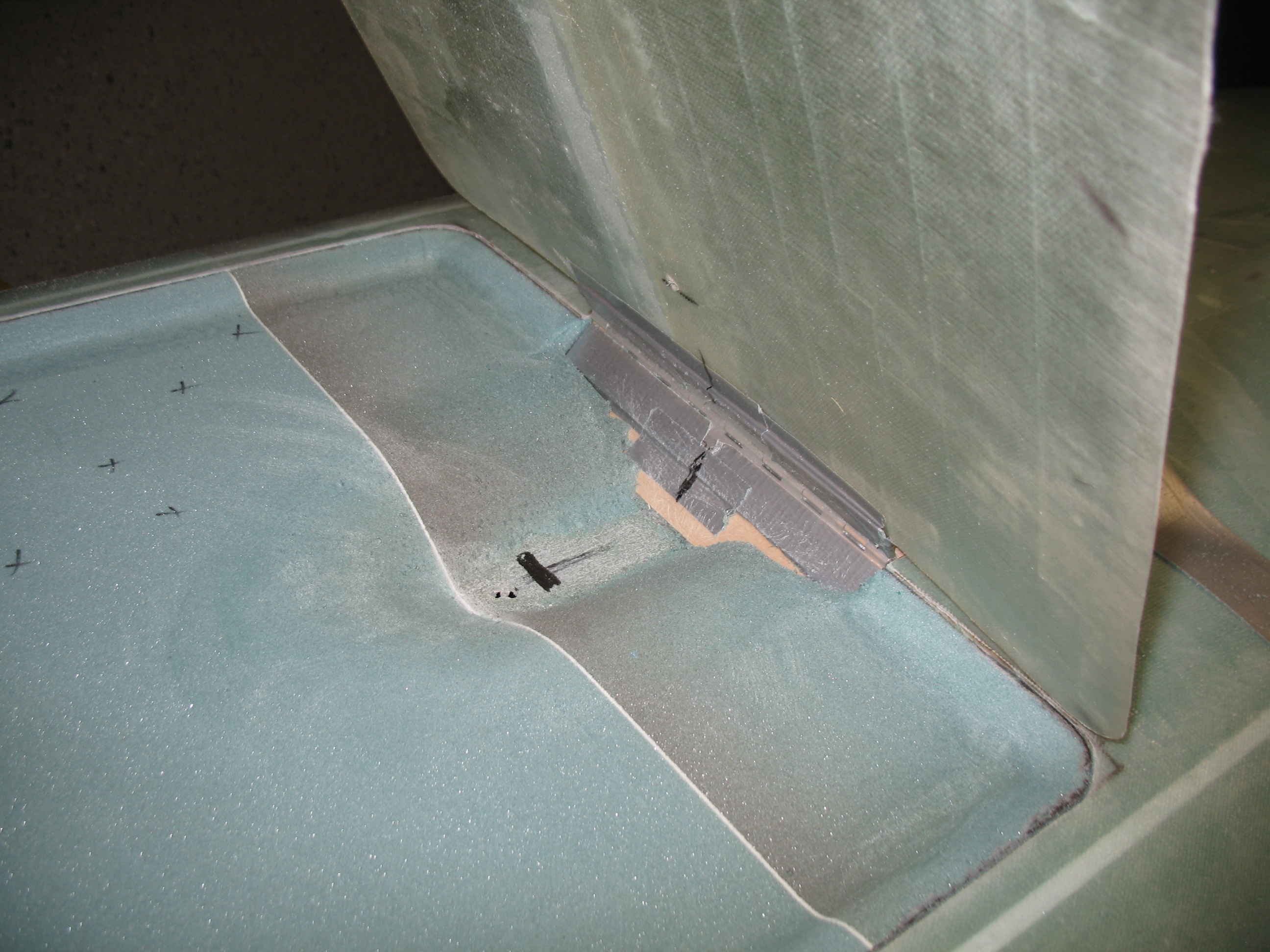
Since I’m using Jack Wilhelmson’s Landing Brake Actuator, I used the measurements out of his included instructions. I drilled through the “landing brake door” at the 3.7″-from-hinge position down through the bottom of the fuselage.
After I got the hole situated, positioned and drilled, I cleared out the foam and sanded it down to the bottom (inside-fuselage) glass just aft of LB23. The depression is primarily for the bracket (LB18) that holds the electric actuator arm to the landing brake door. After I sanded the foam out, I sanded and prepped the underlying glass (again, the glass that is actually the fuselage floor on the inside of the fuselage).
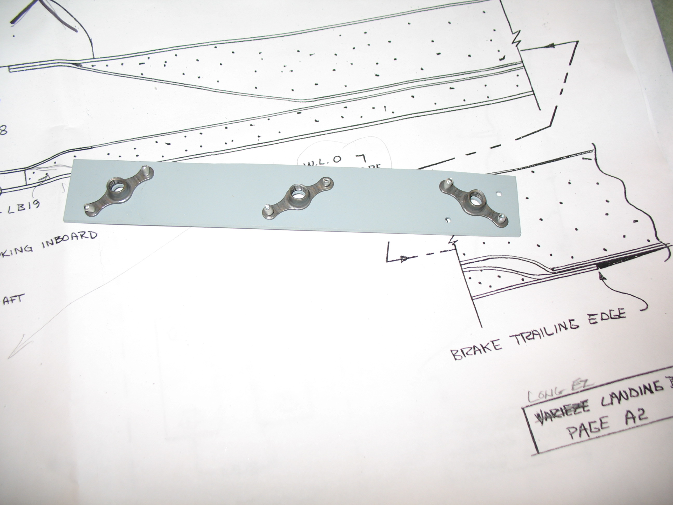
After all that mucking about with the fuselage landing brake foam, the primered 2024 aluminum plate was ready for some nutplates. I pop-riveted the nutplates on the aluminum piece and then lined the whole assembly up with LB23.
I then pre-drilled FROM THE BACK SIDE (where the nutplates will sit) the hinge mounting bolt holes (1/4″) ALMOST (but not quite) all the way through LB23. So, on the face of LB23, facing up/out, I had 3 very small 1/32″ pilot holes showing. On the backside of LB23 (where it mates to the nutplates), I had 3 each 1/4″ holes, matching the pattern of the nutplates, that went about 95% of the way through the plywood… so that I had one little thin piece across the top of each hole. Why? To ensure I kept epoxy out of the nut plates, make it easy to drill out the holes to gain access to the nutplates, and also keep the drill bit as far away from each nutplate as possible.