Project Update

Hey Guys,

I’m happy to report that the install of all the internal CF baffles is complete, including the final gap fills around the edges to ensure minimal air leakage. 

As I’ve noted previously, all the exhaust pipes have been welded, with the required trimming of all the exhaust pipes to length coming soon.  I’ll caveat the exhaust pipe effort with the fact that I may need some welding on the ends of these pipes to get them pointed in the right direction, but I’m of course hoping not.  In addition, I have 2 compression style EGT probes from GRT on hand and will need to have the stainless steel threaded bungs welded to the exhaust pipes to mount those specific probes.

The convergence of a few intertwined components I spoke of before is STILL slowly coming to fruition, which will set me up to be nearly done with the entire engine install, sans the firewall (at this time).  With the CF inner baffles now installed, I can turn my focus on finalizing the aft lower side of the engine aluminum baffle install.  That will, in turn, allow me to identify where the bottom cowl cross rib baffle/stiffener needs to get glassed into place.

I’m still intent to focus solely on the plane for the next however long it takes to finish this bird… ASAP!  

Chapter 3/22 – New backup EFIS/clock!

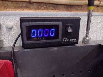
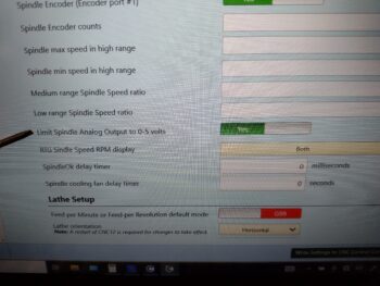
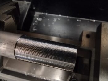
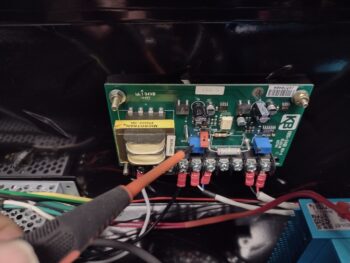
I started off today by testing my removed lathe CNC control box KBSI-240D board’s MAX trimpot to see if it was working or not.  After all my machinations with it installed, I figured I was going to merely confirm that it was a dead potentiometer and set about ordering a replacement.

But, as things seem to be playing out in this new year… I was wrong.  I powered up the board with a homemade 120v plug and hooked up the VFD input to a 9V battery.  I then tested the output with my multimeter as I manipulated the set screw on the MAX trimpot… and it worked as designed!  Hmmm?  Interesting.  Now of course I’ll mount it back into the lathe CNC control box, double-check all the wiring, and see just what the heck is going on!

In other news, about a month or so back I reported doing some fairly in-depth research on a replacement for my MGL clock/timer on my panel.  I like the display and as a clock and timer it had all the functions I wanted.  But as I started pondering more and more, I wanted 2 backup functions on my panel in case either of my GRT EFIS screens went dark: a backup AI (or EFIS PFD) and an HSI/CDI to merely display ILS/LOC/GPS approaches from my GNS-480 GPS box.  In short, if I lost a screen I wanted extra data display points to help ease the load and mitigate the requirement of switching screens on a single EFIS display if it ever came to that.

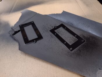
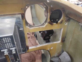
If you remember, I looked heavily at the Kanardia HORIS EFIS and really thought it was a nifty little unit.  My initial thought/concern in replacing the MGL clock/timer —in some-what post haste fashion— is that due to space constraints in the upper left corner of my panel I have it surface mounted on the front of the panel, with #6 platenut assemblies on the backside of the panel structure to secure it.  This of course works better for added instrument panel bulkhead strength, but if I ever wanted to swap this out with a “proper” 2-1/4″ instrument in the future, I would have to remove the entire panel and then do a bunch of messy cutting on a flying airplane (ahem, it WILL be a flying airplane!).

Now, the HORIS looked good, but just as with the other viable 2-1/4″ AI/clock/timer candidates out there (read: uAvionix AV-20s), none of them were fitting the bill of really what I wanted: a clock/timer first, and a back-up AI/PFD second.  And while they had nice screen graphics, the timers were all in reality nothing more than simple count-up stop watch functions.  This is one thing that drew me to the MGL, it had really good clock displays, but also a good countdown timer to boot for use as reminder when to switch fuel tanks.

Me being an avowed Neanderthal, the same thing proves true in my flying: nearly all done in fixed gear high wing aircraft… I don’t want an engine quitting oops simply because I forget to switch the darn tank!

Enter Vlad and 360 Avionics…

I actually found the 360 Avionics ELM 200 (MiniUni 2) on the Aircraft Spruce site.  I then did a good bit more investigation.  Here is a stock photo of this diminutive 2-1/4″ power house (its big brother is the 3-1/8″ MiniUni 3).

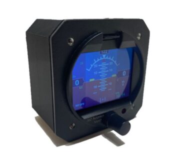
I discovered that the MiniUni2 had 97% of what I was looking for in an instrument to replace the MGL clock/timer:

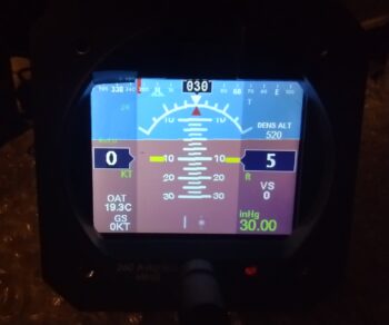
First, the AI/PFD screen has just about every bit of data you’d want in flying behind an EFIS.  With pitot/static, OAT and GPS inputs it gives you all the basic airspeed, GS, TAS info along with a V-speed tape.  It provides Alt, VS, D-Alt and Baro.  In flight it provides your standard rate turn markers, as well as slip skid indicator.  And finally it gives you True (GPS) heading (I would prefer Mag HDG as well, but this is a back-up AI/PFD).

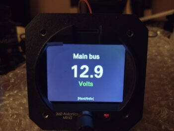
This pic below is my ELM200/MiniUni 2 sitting on my coffee table literally within 30 seconds after I connected power.  I’m posting these pics in the default screen order in which they appear… I will change it up so that the clock/timer screen (shown further below) will be the first screen displayed.

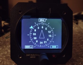
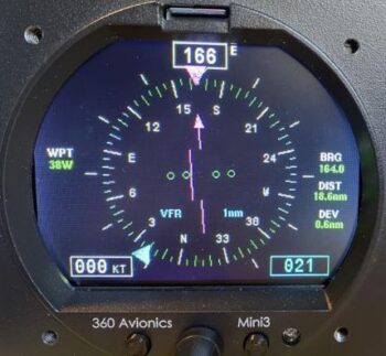
Screen #2 is the “DG,” or technically called the Compass Mode.  It has a heading bug (lower right) and also displays airspeed (lower left).

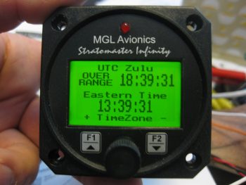
As you can see, the clock/timer screen displays UTC/Zulu time, local time, flight time (initiated when aircraft reaches rotation speed), and a count-UP timer.

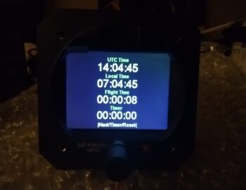
Whoa!! Wait a minute you say!  What about your precious COUNTDOWN timer that you prattled on about?  … well, wait.  There’s more!

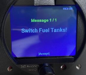
Separate to the countdown timer on the clock/timer screen above, is a menu configurable (Ez-Pz btw) countdown timer specifically for fuel tanks.  Let’s be honest, you and I both know that pilots are crazed anal-retentive OCD types that tend to repeat the same processes over and over.  Once I dial in the frequency to switch tanks, I doubt it will rarely change.  In my book this is a fantastic little feature and fits the bill perfectly for what I was looking for.

It also has this handy little screen, although very redundant and not really required for my configuration.  But good nonetheless.

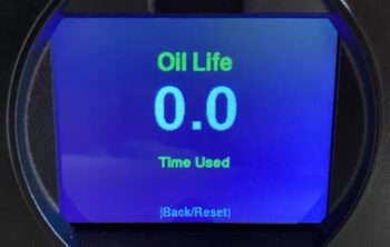
In addition, it does have this even more handy screen, which is a cumulative total of all the FLIGHT time to give you a good idea when your oil change is due.

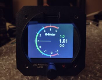
Although I don’t see using this screen below for day to day flight ops, I could see where it could definitely be handy during initial test flights and for testing out different maneuvers.

I’ll note it has a few more individual screens to display altitude only data (including baro), airspeed only data, and local time with flight timer.

Now, I had a good bit of conversation back and forth with Vlad regarding features and quality on his EFIS units.  After I was thoroughly satisfied on the quality front, there was one area that I was not overly satisfied with: the MiniUni 2 lacked a key feature that the MinuUni 3 had… an ability to hook it up to your GPS navigator via a RS-232 connection to drive both a CDI, and a fair bit of GPS track info.

Well, Vlad’s a smart guy and apparently he saw this requirement being asked for in the future, so he had already been working in his lair adding those exact capabilities to the new version of the MiniUni 2.  Thus, I’m happy to report that he built my EFIS as a much more “mighty” MiniUni 2 by adding these cool features.

Another feature that may not seem overly important on the face of it (uh… literally!) is how these units are updated/upgraded.  Both the Kanardia HORIS and uAvionix AV-20s firmware update processes are (IMO) clunky and not elegant (i.e. a much bigger pain than desired).  Conversely, updating the MiniUni 2 is fairly straightforward… it may be a bit difficult to see in all the other pics other than the one immediately above, but just above the screen is a micro-SD card slot.  Simply download the firmware file from your computer to the micro-SD card, plug it into the MiniUni 2, power it up and follow the prompts.

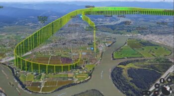
Now, having an onboard storage device in the form of a micro-SD card allows for utilizing another cool feature that Vlad incorporated into this unit (I’ll note that Vlad created a whole line of EFISs that he personally flies in his RV-10) which is called the “Black Box” function.  Once enabled, this included option is a flight recorder that tracks all your flight data.  You can then easily export that data to your computer and open it up using Google Earth.

Finally, here’s a video of Vlad discussing his MiniUni EFISs:

Again, this EFIS/clock/timer is my replacement for the MGL CLT-2 clock/timer, and it will be installed prior to first flight.  I do have plans to replace my 3-1/8″ TruTrak ADI, which is in the works but won’t happen until quite a bit after first flight.

Ok, working to get back onto the actual build!

Chapter 3 – Lathe CNC squawks

No, this is not frontline airplane building, but there are a number of parts that I need to make with this lathe for this build.  I figure I would do a quick overview of a key issue I found, as well as my progress.  Probably as much for me as a future reference as for you as an update.

Analogous to a long airplane building project, since I did a my initial stint of CNC conversion on this lathe the January before last, I had to pick back up where I left off.  I completely failed to remember that I hadn’t even hooked up my spindle encoder to the Acorn CNC board.  Probably due to the overall lack of ability to do any spindle manipulation since I hadn’t done the right mod to the main control board that allows me to control the lathe spindle via the Acorn CNC control system (I did this a few weeks ago).

Now with basic spindle control “operational,” I need to refine it so that when I or a CNC g-code file commands a certain RPM, the lathe responds accordingly… which it is not currently doing.  So today I finished a task that I started about 3 years ago: terminating the ends of the 9 spindle encoder wires with D-sub pins to create a 9-pin D-Sub plug.  These 2 documents gave me the how-to on doing that.

Here we have the encoder wires cut and pinned (pic 1) and then terminated into the 9-pin D-Sub connector, which is plugged into the Acorn CNC-12 board (pic 2).  The red ring terminal is the shielded wire ground.

Notice the 2-post connector just to the left of the red ring terminal?  That is the Variable Frequency Drive (VFD) 0-10 volt output that controls spindle motors on much larger lathes and mills than most home shops have.  Most smaller hobby lathes and mills tend to use a 0-5 volt range to control spindle speed.  More on that in a minute…

With the spindle encoder now installed, I tested out its operational capability.  The good news is that it was spot-on and matched my external lathe RPM readout almost exactly as I cycled through RPM ranges by using the command line on the control screen.

The bad news is that the RPMs I was asking for on the command line screen were not being accurately produced at the lathe spindle.  Again, the no-kidding spindle speed was being reported correctly by both the encoder and the external RPM display, but it wasn’t what I was telling the system to do.

Remember the 0-10 volt VFD output from the Acorn board?  Well, for us home shop bubbas we tend to use a KBSI-240D signal isolator board to translate that 0-10 volt Acorn board output into a usable 0-5 voltage range to dictate lathe spindle speed.  Zero (0) volts translates to a stopped spindle.  5 volts is max RPM, which in the case of this lathe is 2500 rpm.

On the KBSI-240D are two (2) trimpots: one to dial in the max voltage, and the other to dial in the minimum voltage.  Taking voltage readouts while commanding various spindle RPMs has proven that the MAX trimpot ist kaput, TU, no muy bieno in that it won’t allow me to adjust the upper voltage down to 5 volts.  In fact, currently it’s stuck on a whopping 12.47 volts, which is clearly no good for this configuration.  Moreover, this sucker has been the hidden fly in the ointment over the last couple of weeks truly hindering my ability to get the spindle control dialed in.  It makes total sense now after finding it.

Now, a new feature in my new updated (note: not upgraded… yet) version 5.08 Acorn CNC software is that in the configuration is a menu item that allows the Acorn board to output 0-5 volts through the VFD port.  I thought this might be my get out of jail free card, but alas, it did not work either when I tried to hack the system.

Thus, I pulled the KBSI-240D board and will do a final test on the MAX trimpot to see if it is truly bad.  If so, I’ll order a new trimpot and solder it in at some future point.  Since the lathe is currently spotty, I finally just pulled the trigger on some stainless steel rod, a M8-1.0 tap and 7mm drill bit to create my own stainless steel bungs for the compression style EGT fittings.  Ones that won’t be so bulky and heavy.

Yes, during the colder weather I did want to get my lathe CNC conversion completed and get it online.  I’m clearly much closer, but with the weather temps inching up as we move towards spring, I need to get back onto the no-kidding airplane build.


Chapter 3/19/22 – Lights & Lathe

Just a quick post showing that I finally got the wing light mounting brackets painted and clear coated without any further incident.  After the couple coats of clear coat cured, I then baked the light brackets in the oven at 175° F for 2 hours to harden up the paint as best possible.

I of course then worked most of the day on trying to get this lathe CNC finalized.  Currently I’m back on the spindle control piece of the puzzle since there are some squawks there that need to be fixed.

Chapter 3/19/22 – The struggle is real!

The struggle against the shop critters that is….

Case in point: I primed and painted my wing light mounting brackets last evening and left them to cure overnight, and had planned on clear coating them after this good 24-hour cure.  However, upon entering the shop I saw some type of footprints and very visible scratches on the surface of one of the brackets (note bottom of pic).

So I cleaned up the scratches and prints off the brackets and hit them with another couple rounds of paint.  Tomorrow I plan on clear coating them… hopefully without issue.

I then did another big round of cleaning up the shop.  Alas, the squirrels, et al, really did do a number on my shop while I was gone on my Christmas/New Years adventures… there was downed insulation panels, tufts of pink fiberglass and poop pellets everywhere.  From here on out I really have no choice but to remove their primary objective: the ceiling fiberglass insulation.  They love this stuff as they burrow their way into it, pissing and pooping the whole way… and then shred it so that it comes down in a myriad of pieces vs the complete whole panels that I installed.

I’ll again remind ya’ll that the combination of the persistent colder weather along with significantly much less insulation on the ceiling of my shop is hampering my ability to keep the shop warm for composite work.  Thus my current meanderings on other tasks.

Speaking of which: back on the lathe, I did some facing and touch-off cuts on some scrap aluminum stock as per the Centroid Acorn CNC-12 Lathe manual in order to set up my CNC-12 tool library.  Below is a cut I made with a carbide insert tool with a fairly shallow depth of cut and a somewhat rapid feed.  I think it looks kinda cool so I threw the pic in here.

And here is a shot of the screen as I add all the tools to the Acorn CNC-12 tool library.

I’ll note that my initial smattering of lathe tooling is fine for hacking my way through some manual lathe ops and some basic CNC, but not —as I’m learning— for any refined or optimized CNC lathe operations.  Thus, I do now have a decent amount of tooling on order and am awaiting those to arrive as I strive to get seriously online with my ability to use the lathe to make serious parts.

Pressing forward.

Chapter 3/19/22 – More Lathe Stuff

Today I continued pressing forward with the lathe CNC conversion by updating the Acorn CNC control software from version 4.64 to 5.08.

As I was writing out my task to-do list for the day, I got a call from my good buddy and fellow canardian Marco.  We of course discussed Long-EZs and projects, but we mainly discussed machining… specifically lathe CNC operations.  The call was perfect timing since I had a number of questions regarding employing CNC on a lathe, which is a much different animal (a more hybrid blend of CNC using less Fusion 360 CAM and a whole lot more Acorn CNC macros, or “canned” lathe cycles) than CNC on the mill.

When setting up an Acorn CNC control computer, it must be a dedicated CNC computer.  The Dell laptop I have has not been connected to the outside world via Internet in years, to keep Microsoft from sneaking in software that may crash a CNC program.  However, the catch-22 is that when new Acorn software is released, it is based on the current Microsoft .NET framework, with all the latest updates.  Thus, the first step in updating the Acorn lathe CNC software is to “briefly” connect the computer to the Internet and do a controlled Microsoft Windows update.  As you can imagine, this took multiple hours (pic below from later at night after new Acorn CNC software update to v. 5.08… note column of white buttons at left on gray panel: these are new pre-set lathe cycles that require simple parameters to be inputted before executing, an upgrade over the older software that didn’t have these pre-programmed macro/canned cycles).

While my dedicated CNC laptop was getting all the security and Microsoft .NET framework updates, I pulled down about a half dozen panels of pink fiberglass insulation that were clearly in use by unwanted intruders.  Yes, I may have won some battles, but the squirrels and giant field rats won the war.  The ceiling insulation is on its way out.  Currently my shop smells like a bathroom in an inner city bus station… the ever-present smell of squirrel piss wafting through the air.

I loaded my truck with a bunch of the nasty removed insulation panels and took them to the dump.  Upon my return —as the CNC computer slowly did its update thing— I did a good round of cleaning in the shop.

The good news is that the fewer the insulation panels, the less places for the rodents to invade and occupy.  And yes, I’ve tried traps, poison, ultrasonic blasters, barriers, etc. to keep them at bay.  The bad news?  Did I mention, it’s still cold??  So no major epoxy-based tasks until it warms up.

During yet another phase of my CNC computer update (it took about half the day), I cleaned up the inside corners of the wing leading edge light brackets, tested their fit on the actual lights, then cleaned up the brackets for a round of primer, then a couple of rounds of black paint.   I’ll clear coat them in the next day or two.

With the Acorn CNC dedicated computer finally updated with the latest round of Microsoft junk, I once again took it offline and locked it down.  I then proceeded to backup my old 4.64 software version (in case the new one crashes) and then updated my Acorn Lathe CNC software to version 5.08 (see pic above).  I then spent about 45 minutes updating the operating parameters in the software that is specific to my system (I took screenshots earlier of all these screens).

I’m happy to report that the lathe CNC software is updated, now back to getting it configured to make some chips!