Chapter 21 – Just another oops!

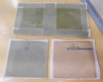
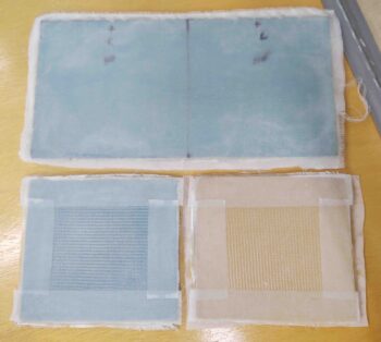
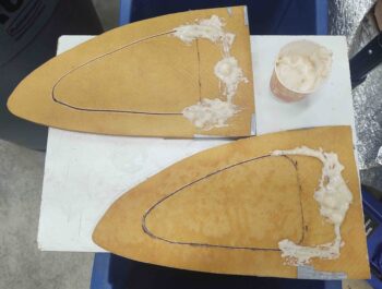
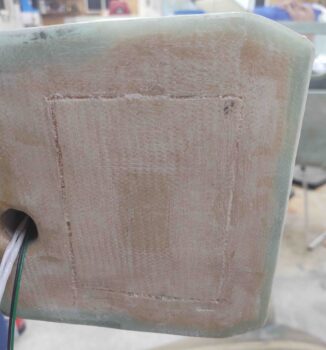
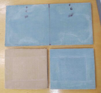
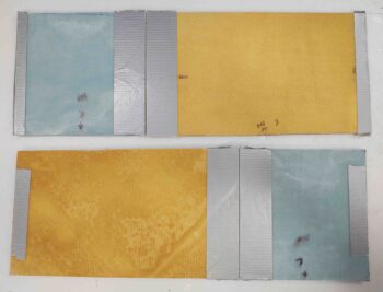
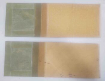
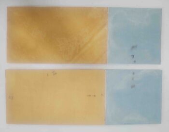
I started out today pulling the peel ply from the 3/8″ thick foam pieces I laid up a ply of BID on yesterday, both sides.

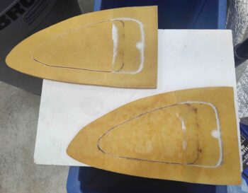
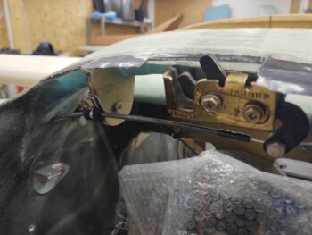
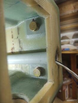
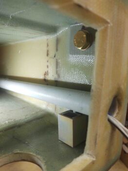
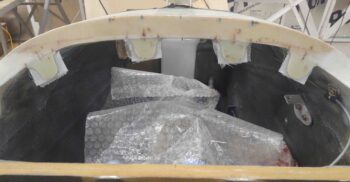
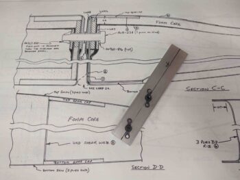
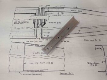
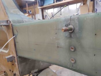
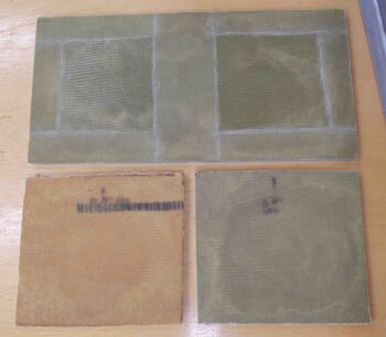
The rectangular piece at the top is actually the 2 extension plates that will be added to the BAB baffles that came with the Feather Light strake kit.  Again, since I did the “elbow room” mod and extended the GIB seat area fuselage/strake opening much further aft, I need to extend the interior fuel tank wall from the BL23 rib to the interior edge of the current fuselage sidewall.

The lower glassed pieces are for outboard fuel walls that I’m adding since I’ll be losing a bit fuel with the above mod, I’m adding a bit of that lost fuel capacity back on the outboard side of the fuel cell.

As I mentioned in yesterday’s blog post, I used MGS epoxy for the layups on the non-fuel side of these foam pieces.

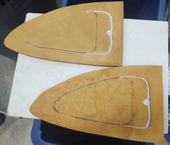
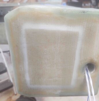
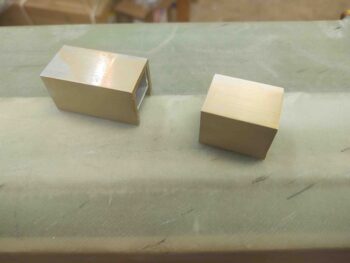
I then cut and sanded the rectangular foam plate into 2 pieces.

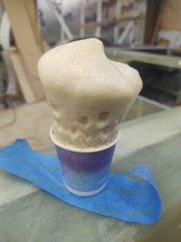
All my work being under the watchful eye of a shop observer… he was hanging around quite a bit yesterday as well!

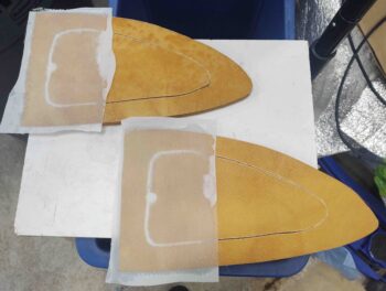
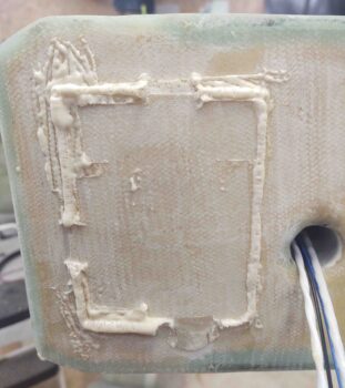
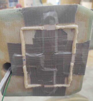
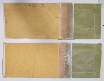
I then prepped the BAB baffles and the freshly glassed foam extension pieces for micro-joining and glassing.

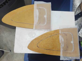
I used EZ-Poxy to whip up some micro to join the respective extension pieces to the existing BAB baffles, and then laid up a 2-ply BID tape to the seam.  Since this joint will be exposed to fuel I laid it up fairly wet.

I then peel plied the layup.

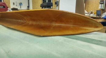
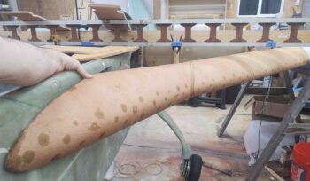
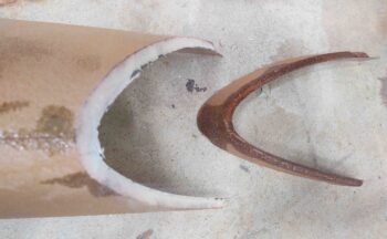
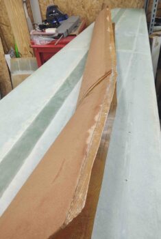
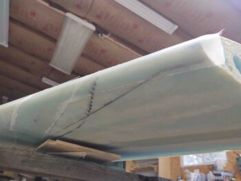
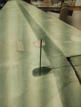
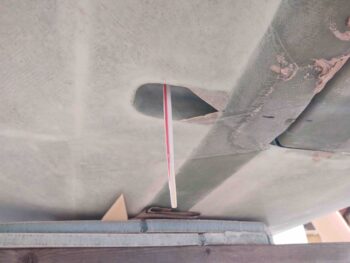
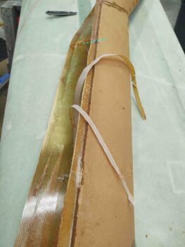
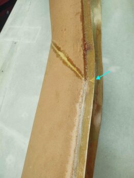
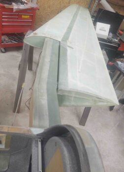
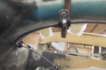
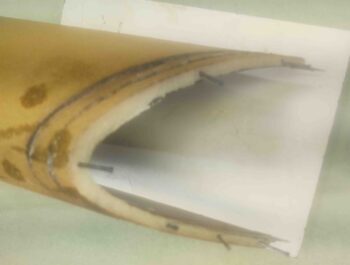
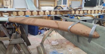
My big oops was I thought I had both ends of the left-side strake leading edge fairly dialed in.  First, trimming the outboard edge, as slowly as carefully as I tried to do it, is like installing crown molding.  You keep shaving a 32nd of inch at a time and that last cut leaves you with a stupefying 1/4″ gap!

So I had a small gap at the outboard end after the initial trim.  However, my angle and position of the BL 23 kink was off enough that when I trimmed a bit more off the inboard edge of the prefab strake leading edge, it created a significant gap on the outboard end.

To be clear, the gap isn’t shown below, I moved the strake leading to allow me to micro the pieces I cut back into place…. yep, I love RE-DOING stuff! (ugh).

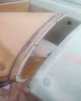
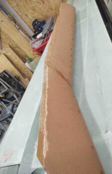
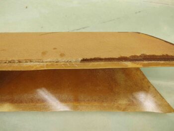
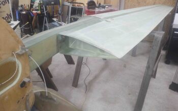
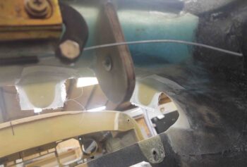
Above was round 1, below is round 2 of adding in another slice of LE back onto it.  I need to do one more piece and I’ll have the outboard edge back to a workable state without a significant gap.

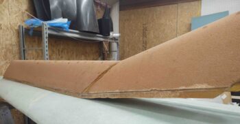
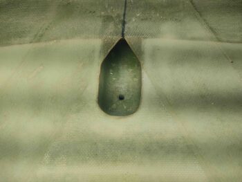
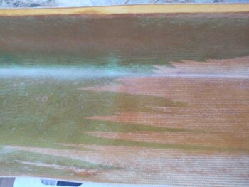
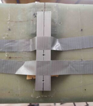
This pic is a bit blurry, but you get the idea . . .

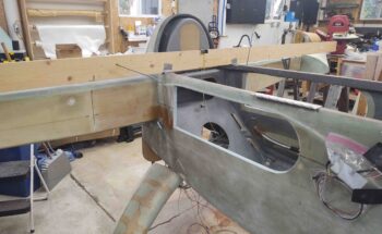
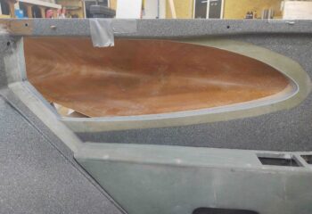
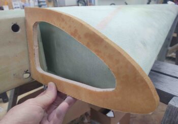
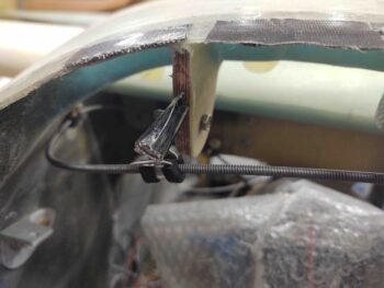
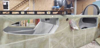
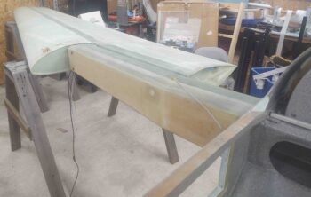
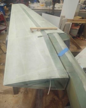
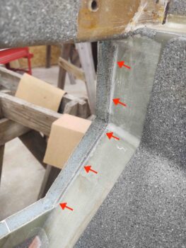
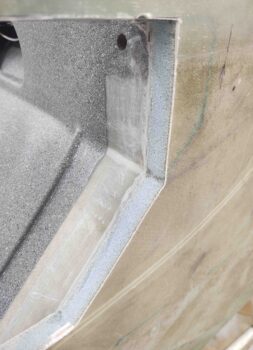
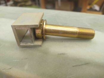
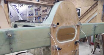
To avoid the outboard fitting issues that I had on the left side, on the right side I decided to mount my outboard rib FIRST before fitting the leading edge into place.

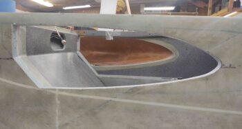
I wanted a slight inset on the outboard rib, somewhat like the wings have, just not as deep: so I used some 5/16″-ish thick OSB strips as spacers for that.  I then trimmed and shaped the outboard rib, recutting out the middle area as well.

I then clamped my foam skin spacer in place on the bottom, set the outboard rib in place with micro and a couple of dabs of 5-minute glue.  I then used micro for the fillet and laid up a 1-ply corner BID tape.

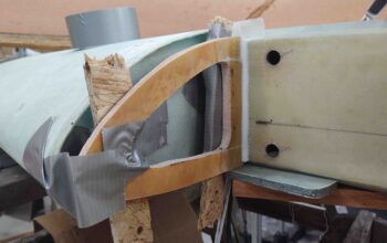
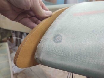
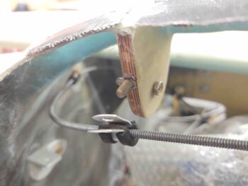
A few hours later I pulled the spacers out and trimmed the corner glass.

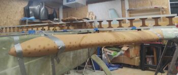
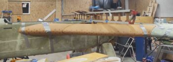
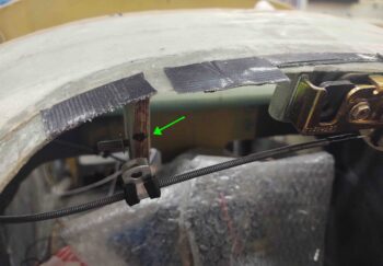
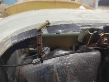
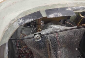
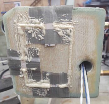
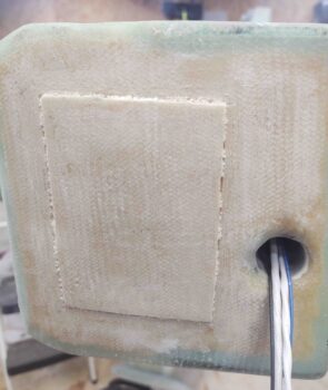
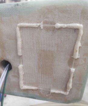
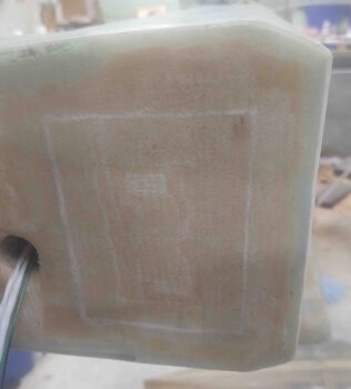
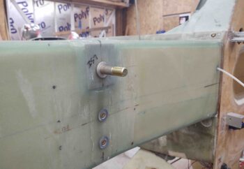
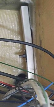
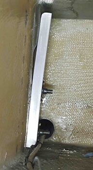
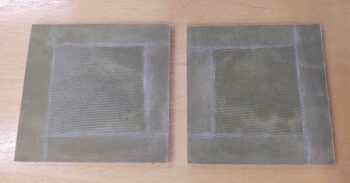
A bit later I pulled the peel ply on the new extended BAB baffle layups, then razor trimmed and cleaned them up a bit.

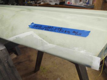
I cleaned up the opposite side and prepped the seams for a 1-ply BID layup that I’ll do tomorrow.

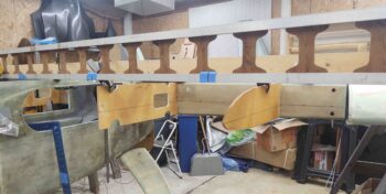
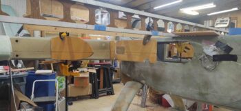
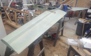
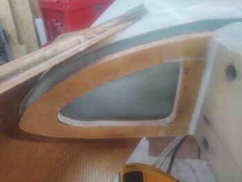
I was able to get a signifiant initial trim of the inboard edge of the right side strake LE… here is the initial fitting of the right leading edge.

And with that, I closed up shop and prepped to ring in the New Year!

Chapter 21 – Strake Prep Complete

This blog post actual covers today and yesterday.

Yesterday was all about prep work for the individual strake components.  I sanded the foam edges adjacent to the top & bottom flanges on the strake LE structures.

I also broke out the laser level and marked the 17.4 WL on the fuselage and CS spar, as well as on the ribs, baffles, etc.  I also did a final trim and cleanup on all the component pieces.

Today I got to work on setting up a wood cross bar and then marked the centerline on the wood using my laser level.

I then marked the BL23 and BL45 locations on each of the CS spar front faces.

I then cleaned up and added another long straight board and measured and marked the CL, BL23 and BL45 on that as well.  I then trial fitted the aft part of the BL23 rib and the BL45 rib, using hot glue & clamps to keep them in place.  First the left side . . .

then the right . . .

With the aft sections of the BL23 ribs in place, I could then determine how much of an extension was required for the BAB, or Baggage Area Baffle, which is the aft internal wall for the fuel tank.  Since I cut the GIB strake opening much farther aft –nearer to the CS spar– for GIB comfort, I need to add an extension to the BAB baffle to reach from the midpoint of the BL23/R23 rib to the aft end of the GIB strake opening.

I laid up both side extensions on one piece of 3/8″ foam for now (the top), using EZ-Poxy for the internal layup (shown).  In addition, I laid up a ply of BID each on 2 small foam plates that will be added aft fuel walls on the outboard side of the strake between the R45 and OD ribs.  With the OD rib the new outboard fuel wall, I’ll place a fuel tank wall about 2/3rds aft from the LE towards the spar to keep the fuel towards the front and minimize negative aft CG effects.  It should become clear what these are for within the next few days.

With the layups complete and curing, I then got to work cleaning the PVA off the interior pre-fab strake LE structures.  I used a heated concoction of white vinegar and Dawn dish soap and it worked a treat, albeit with a bit of elbow grease scrubbing with an abrasive 3M pad.  You can see the strake LE on the left has no more PVA residue, while the one on the right still has an extensive amount on the interior surface.

This is the PVA-laden strake LE above after a few minutes of soaking with the vinegar & Dawn soap solution.  I then scrubbed it thoroughly afterwards.

I also sanded the interior glass surfaces of the strake LEs with 100 grit sandpaper.

With the interior glass surfaces cleaned and sanded, I then did an initial test fit of the left strake.  As you can see, it definitely needs some trimming… especially noteworthy is how far out the BL23 kink is on the strake LE piece.

A closeup of the left strake LE BL23 kink before trim.

I then spent about an hour slowly trimming down the outboard and inboard edges of the left strake prefab LE.

I eventually got fairly close, but still need a last final trim or two to dial it in.  Still, I’m happy to have a visible LE at this point of the strake build… definitely not something I’d have if I was doing the plans method!

Here’s a look at the inside edge of the left strake LE.  By simply being taped into place it’s of course off just a bit, but definitely close at this point.

And a shot from the other side of the fuselage.

Since I glassed the strake fuel foam panels earlier in the day, my last task for the evening was to layup a ply of BID on the other side to allow them to cure overnight.  Since the opposite sides of all these panels won’t be touching fuel, I went ahead and used MGS epoxy for both ease of layups and a quicker cure time.

I also peel plied these layups as well.

Tomorrow will be a half work day since I have plans for New Years Eve.  But I will make every effort to bring in the New Year with both strake leading edges trimmed to fit and ready for mounting!


Chapter 19/21 – More Strake Prep

I got back home from Greensboro at nearly 7pm tonight, and spent a bit unloading the vehicle and getting situated.

I wanted to get a good 2-3 hours in on the build tonight, and started with pulling the peel ply on the left wing tip leading edge repair layups.  I did a quick razor trim and also cleaned up the peel ply edges a bit.  It looks good and I’m happy with the repair… task complete.

I then got busy on the strake outboard ribs.  I pulled the peel ply from the 1-ply BID layups and razor trimmed the edges.

I then added some micro to the foam seams and laid up another ply of BID on the other sides of the strake outboard ribs.

I then spent nearly an hour and a half pulling the peel ply from the aft flange –both top and bottom– of the right strake prefab leading edge assembly.

As on the left prefab strake leading edge assembly, the peel ply ended up being under the foam by about 1/4″ and needed extracting.  This doesn’t leave the foam edge in an overly attractive state, but since the hard epoxy edge needed to come off anyway, it’s not that much more destructive to remove the peel ply from underneath it as well.

I then spent about 30 minutes cleaning up some more bondo off both the left and right wings.

Tomorrow I plan on focusing primarily on the strake components prep to allow me to then trial assemble all the parts and check fit and configuration.


Chapter 19/21 – Wing & strake tidbits

As I mentioned in last night’s blog post, I had every intention of working on the prefab strake leading edge, ribs and baffles to prep them for the upcoming strake build. However, when I walked out of my house to head towards the shop I noted how warm of a day it was, at least compared to the weather lately.

The shop was a tad warmer than it has been recently, with the basic wall thermometer showing in the mid-70s.  I made a decision to do some layups first while the shop was nice and toasty, and possibly work on the strake parts afterwards (yeah… right!).

The first task was a repair on the left wing’s leading edge tip that has literally been on my to-do list since right after I built the wings in 2012.  I don’t remember the particulars, but somehow I overlapped the top wing skin onto the peel ply that I had applied to the ply of BID on the outboard bottom wing… the BID being a foundation for the ensuing plies of UNI for the winglet attach.

Again, for whatever reason or oversight, I ended up with about the outboard 9″ of the wing LE having top wing skin glass overlapping onto a ply of peel ply.  I had since removed the covering glass and the offending peel ply, but had yet to repair my mistake.

So today I started off by sanding the angled top skin glass overlapping onto the bottom of the wing, from the center of the LE down underneath, to smooth out the transition.  Using the Fein saw back when I removed the top skin overlap, I had inadvertantly cut into the skin at two spots on the front underside of the wing just aft of the LE, each less than an inch long. In addition, all along the outboard 9″ of the LE centerline was a cut line varying from about 0.02″ to 0.05″ deep (I tried to get an initial pic but the lights washed out the details).

I whipped up some flox and filled the two slits and the cut line depression, and then laid up 1 ply of BID to cover the angled portion on the bottom side of the wing coming up, over and outboard to the top of the LE.  I then laid up another ply of BID along the LE edge to cover all the offending errant Fein saw cuts and depressions, and to ensure the top skin was joined adequately to the bottom along the outboard LE (blue tape was a note to myself on tasks required).

I then of course peel plied (properly, this time around!) the layups.

Since I was in glassing mode today, my next task was to remedy yet another sin of the past.  This time a much more recent one . . . apparently the outboard strake rib (added in the Feather Light kit: not per plans) is cut significantly longer than required to allow for trimming down as needed.

I didn’t realize this until the wings were actually on and I was checking the strake outboard rib fit with the wing . . . whoa!  As you can see: way too long for what I need.

Yep, leaning forward to be ahead of the game can often come back to bite ya! As you can see I had already cut the center out of the outboard ribs to allow me access into the strake (for GRT magnetometers on the left side, and possibly S-Mode Transponder & antenna on the right side).  Clearly the 1″ strip I left at the aft end of these ribs would not be enough if I need to trim these things down to fit, starting at the aft end of course.

I needed to add in some more mass on the back side of these ribs to allow for trimming during install.  Since I still had the center cutout pieces I would simply put them back in place and recut, leaving a much more robust aft end to trim.

Instead of messing with micro alone to reset the previously cutout rib center back in place, I turned to my new found friend: pour foam [Note the new interior lines I quickly drew up on the cutout center pieces].

After about half an hour I cleaned up both outboard strake ribs and then covered the bare foam in each seam with micro.

I then laid up a ply of BID on each rib and peel plied the layup.  When I return from my Christmas break I’ll lay up a ply of BID on the opposite side of each rib.

Although I was technically out of my allotted time for working in the shop for the day, I had a decent little bit of micro and epoxy left over… not a ton, but certainly enough to knock out one more quick task.  I had mentally noted another item on my wing to-do list was installing the water/moisture drain from the top wing bolt trough, through the wing, down to the bottom bolt trough.  This is a mod spelled out in a CP (which I don’t have the info on currently).

This is my initial drilling with a long 1/8″ bit which I left embedded for the pic (Note the removal of the left wing incident level board).

I then widened out the install hole to just under 0.3″ for the straw to fit, although I would have preferred a narrower diameter straw.  I believe the globs of raw epoxy in the bolt trough are from epoxy oozing out from the spar cap during those layups (best guess… it’s been so long!), and is also on my to-do list: to clean out.

Since I was in a hurry (as per usual!) I simply pulled the straw down and then set the top of the straw even to the top of the hole in the upper bolt trough.  I did back fill and smooth out the area around the straw where there were very small gaps between the straw and surrounding hole.  I left the straw to cure and then also filled some minor gaps on the straw vent on the right wing, which was installed around 2012-13 timeframe.

And yes, still a bit of bondo cleanup to do on the bottom of the wing at the spar junction.  I’ll wait until the wing is back off the plane before I tackle that… minimized upside-down sanding to spare the shoulder for this old dog.

With that, I locked up the shop, packed, loaded up and headed out to Greensboro for my Christmas break.

By the way, Merry Christmas everybody!


Chapter 13/21 – Strake LE prep

I started out today reviewing the initial strake build steps both in the plans and my self-edited instructions that I modified from John York’s excellent CSA newsletter writeup on his install of the Feather Light Strake Leading Edge Kit. Part of that overview was also reviewing 15 separate strake build-related topics in the CPs…. about an hour total.

I then went out to the shop to check on my threaded adel clamp stud that I floxed in place into the right hinge bracket for the aft nose/avionics cover.  Last night I wrapped a bunch of thick duct tape around my initial thread-protecting piece of electrical tape to serve as a a depth stop of sorts.

I took the tape off within a few seconds and was met with this… not bad at all! I’ll take it.

I then tested out the fit and configuration of both the adel clamp and the nose hatch latch cable… both look great.

Next, I then spent well over an hour finalizing the sanding and shaping of the fuselage strake cutouts.  Probably a few very minor tweaks that I’ll find here or there as a slight divot or bump catches my eye, but overall I’m very pleased with the shape and cleanliness of the cutouts.

An interesting note that I read in one of the CPs —that was NOT in my instructions anywhere— was that the glass edge next to the foam on the top and bottom of the Feather Light prefab strake LE was peel plied.  Who knew??  Well, I investigated that and found that there was indeed peel ply.

So I set about to remove it on the left strake LE (peel ply above blue dashed, and none below it).

I then noted this green residue on the interior glass of the prefab strake LE, which I assume is PVA from all the research that I’ve done.

After I got one strip of the peel ply off, and my curiosity satisfied. I pulled out the plans and started measuring all the strake ribs and baffles to compare them to the plans configuration. I kept noting that on most of the pieces they were about 0.1″ greater in dimension than what the plans called for.

Not wanting to mess anything up, I decided to check with the source before doing something like trimming all the pieces down to plans dimensions just to learn that they were supposed to be that size for this strake LE kit.  So I called “Feather Light,” which is now Aero Composites.  I spoke for a good half hour with the new owner, Gregory, who was very much up to speed on the Strake LE kit, although Feather Light had stopped selling them years before he bought the company.

I confirmed the green residue was in fact PVA, and that I should hold off on trimming any parts until after I had mocked them all up.  Good stuff.

I then went out to buy some more Christmas gifts and went over to some friends house for a few hours.  Tomorrow I’ll be heading up to Greensboro for a few days over Christmas, so no building for a few more days (although I will get few hours in tomorrow morning).  I will however be fine tuning my strake build task list.

When I returned home from my friends’ house, I then got to work pulling the peel ply from the top side of the left prefab strake LE.  I will say that when they laid in the peel ply on the leading edge-to-top skin flange, they positioned it a bit too far under the LE foam, by about a 1/4″.

This meant I had to remove a good bit of the edge of the foam to get the peel ply out and removed. It’s really not that big of deal since the foam has a hard epoxy-soaked edge that needed to come off anyway.  There’s no hard measurements for the top skin foam so I can simply “add” a 1/4″ to the front of the top skin foam piece and all should be fine (blue arrow is demarcation between no peel ply [bottom] and peel ply)

Realizing that the hard epoxy-soaked edge needed to come off, I then flipped the left pre-fab strake LE over and did the same on the side I had previously removed the peel ply from.

My main goal tomorrow will be to work prepping both the strake leading edges and the ribs and baffles to be as in an install-ready condition as possible so I can hit the ground running when I return from my Christmas break.

I then spent the last 45 minutes of my evening in the shop removing old dead bondo off the left wing.

Chapter 13/19/21 – Wings on again

Over the last couple of days I’ve been tweaking the custom sawhorses that I built specifically for attaching the wings to the CS spar a few years ago.  In this shop, on hard concrete, they needed to be a couple inches lower in height than when I originally used them.

So I measured the height of each one and cut all the bottoms of the legs off so they would be around 41″ high (after I installed the wings I of course discovered they could have been an inch or two taller, but better to shim a bit than have to drag them back outside and recut).

I then (re)installed the right wing in prep for aligning the pre-fab strake leading edge, and to test out my wing bolt mod.

After about 10 minutes of finagling the inboard and outboard elevation of the wing I was able to cajole the wing onto the wing bolts.

I did discover that with using the washers called for in the plans that my AN8-21A outboard wing bolts are a hair short.  Not to worry since I have some spare AN8-22As and AN8-23As on hand.

I then (re)installed the left wing and found the same issue with the outboard wing bolts: just a tad too short.

Here we have both wings (re)installed.  As a point of note, this is the first time the wings have been installed since I originally installed them to the CS spar a few years ago.

I then tried out Waiter’s (iflyez.com) trick using a level to check the incident of each wing in comparison to each other (2×4 is to get the level at level before measuring from the bottom of the level to the wing TE, same spot on each wing).  I did this 3 times on each side, and the farthest off was just a hair over 0.020″… not bad.  My typical measurement was 4.35″ at the top of the TE, and 4.40″ at the bottom of the TE — again, on each side.

I had to run out and do some Christmas shopping and run some errands, so on my return I decided the shop was warm enough (it’s been really cold this winter) to do some floxing.

I need a threaded stud to mount the nose hatch latch cable adel clamp (my first spot torques the cable too much) and decided to use the front edge of the aft nose/ avionics cover right side hinge bracket.

I marked the stud location with a black Sharpie.

Here is the bolt I used and merely cut the head off of . . .

And used it to test the drilled hole diameter first . . .

A better shot.  My apologies, but I did cut the bolt and flox it into place, but failed to get a pic of it… which I’ll do tomorrow.

My next task was to remove the raised edge on each side of the pilot seat bulkhead where I initially cut the strake opening for the baggage compartment, left over from the flox fillet and glass from the original seat bulkhead to sidewall attachment.

I used the Fein saw to remove the majority of the offending glass ridge, and then hand sanded the remainder… as is represented here on the left side of the seat (I did the same on the right side).

Also, I did finish sanding the front right strake opening and plan to finish the remaining fuselage strake openings tomorrow.

Not surprisingly, I’m way behind schedule on the strake build. I do plan on getting the initial layout done before I head out of town for a few days over Christmas.  With the wings on and looking good I can really jump into the strake build full bore from here on out, taking into account breaks for Christmas and New Years.

Chapter 14/19 – Spar reassembly

Of sorts . . .

Today was all about getting the temporary access holes on each of the CS spar filled back in.  If you remember, I had cut out a rectangular piece on each end of the CS spar to allow access to install the outboard wing bolt brackets.  With that job complete it was now time to get the spar put back together to press on.

My first task was to sand around the temp access holes and then the removed rectangular pieces on each end in prep for glass.

After prepping 3 taped popsicle sticks with tape to hold the access piece in place, I then whipped up a very small batch of pour foam and slathered it on the foam edges of the temp access hole.  I then placed and taped the left side access piece in place.

A while later I pulled the taped popsicle sticks off.

And then cleaned off the excess foam.  Since I only used 3 popsicle sticks to hold the access hole piece in place, and with only 1 piece of tape securing the sticks to the rectangular piece, it resulted in a bit of heaving action from the foam that pushed the piece outboard nearly 0.050″.  I think this was exacerbated by my originally cutting out the perimeter of the piece at an angle (like the lid of Jack-o-latern).

After looking around for a good 15 minutes I found the fourth taped popsicle stick and used it on the right end of the CS spar.  I also added considerably more tape to secure the popsicle sticks to the piece, which seemed to do the trick in preventing the curing foam from pushing the piece outboard away from the CS spar end plate.

After allowing the foam to cure for about 30 minutes, I then removed the taped popsicle sticks.

And did a final prep for glass.

Interestingly, I used less than 1/8″ each of part A and part B pour foam in the bottom of this cup . . . it really does seem to expand over 30 times it’s original volume!

I then cut up and pre-pregged 1-ply BID tapes for the perimeter of each access piece.  On the left side I added a small flox ramp around the piece edges for better glass transition.

Whereas the right side was pretty straightforward with some micro applied to the small perimeter of foam first, then the 1-ply BID tapes.

Since I didn’t originally peel ply the end plates of the CS spar I followed suit here and left the layups bare.

With the nights getting down around freezing, I did put some heat lamps on the layups a couple feet away just to keep them generally warm overnight.


Chapter 14/19 – Building Bridges

Today was all about getting the outboard wing bolts installed.  Again, I’m doing the quasi-permanently mounted wing bolt mod where the wing bolts will all be facing aft and secured with brackets.

I started on the left side and set the AN8-21A outboard wing bolts in place.

For each bolt-securing large bracket I needed to keep the 1″ depth in order to allow the bracket assembly to clear the electrical & antenna cable conduit that runs along the aft interior wall (see above and 2nd pic below).

However, to keep the bolt head pressed up against the interior aft wall fairly tight, I needed an interior spacer.  I test fit a smaller U-channel piece installed into the larger U-channel bracket, and it fit a treat.  Notice that the smaller U-channel is somewhat press-fitted into place “backwards” to create a spacer to press against the top of the bolt head.

Here you can see the electrical & antenna cable conduit that runs along the aft interior wall of the CS spar, which is a non-plans mod. I set the bottom wing bolt bracket in place to check fit, and verify the offset was enough from the back wall to allow for a cross “bridge” between the upper and lower bolt brackets . . .

Which are shown here.  The upper bolt bracket is on the left and is a bit longer than the lower bolt bracket.

I had originally made up some 1/8″ thick flat 2024 plates to use to connect the upper and lower outboard bolt brackets, but they were a bit shorter than I wanted them to be.  I couldn’t readily find any more plate stock so I just grabbed some of the extra U-channel I had and figured I would create a bridge by mounting a long length of U-channel (below) connected to the individual U-channel bolt brackets.

These look fine in the pic below, but a close inspection would not win me any beauty awards for these brackets… considering I made them in my time-honored neanderthal hand-machining method (chop saw, hole saw bit and wet sanding) since my milling machine is not operationally online yet.

Besides snazzing them up a bit, although they’ll rarely be seen, the main reason for the holes is to lighten them up.

An initial test fit with the outboard wing bolt brackets (gold) and the connecting bridge (silver).

Here’s the right outboard wing bolt bracket assembly ready for install, after I put it all together. And although I’m not a fan of buttonhead screws, since I have so many of them on-hand I decided to use them to attach the bolt brackets to the bridge.

Note the interior spacers that I pop-riveted into place.  There’s still just a scant bit of a gap between the bolt head and aft CS spar wall, but nothing major that will keep these from working just fine.

I then did a quick test fit to ensure I could fit the outboard wing bolt bracket assembly up through the bottom access hole on the outboard of the CS spar just in case I need to remove or replace it.  My measurements were good and it fit fine.

The outboard wing bolt bracket went in nice and easy and I had it installed in less than a minute.

Here’s a shot from the aft outside angle showing the wing bracket assembly-securing countersunk screw equidistant between the 2 large wing bolts.

I then repeated the assembly process for the left side outboard wing bolt bracket and installed it as I did the right side.

And then grabbed a shot of all 6 installed wing bolts.  The weight penalty of this mod is a little over half a pound.

The only thing left to complete my modified wing bolt install is to replace the temporary access plates that I cut out of each end of the CS spar.  I’ll try to get that knocked out tomorrow.


Chapter 13/14/19 – Nose, and Wing Bolts

I started off tonight with some layups to get something curing right off the bat.  I cut and pre-pregged 4 sets of 2-ply BID for the front side of the 4 CAMLOC tabs that will secure the front side of the aft nose/avionics cover.

After I laid up the BID I peel plied it.

Here’s a couple shots looking aft at the right side and left side pairs of CAMLOC tabs.

My next goal for the evening was to get the inboard wing bolt brackets made up to allow me to install the inboard wing bolts from inside the CS spar facing out and aft, just opposite of how they are installed per plans.  Again, with all the wing bolts secured inside the CS spar facing aft it will make it much easier to put the wings on and take them off during the duration of the build.

I started by trimming and cleaning up the U-channel brackets.

I then set them in place on the bolts (they fit snugly) with the bolts facing in backwards (aka “per original plans”).  I then marked a centerline on both the brackets and the CS spar aft wall.

You can see both the centerline and the bracket-securing screw holes on the left inboard bolt hole (I moved the screw hole up slightly on the top).

I then drilled the bracket-securing screw holes and riveted 2x K1000-3 nutplates onto the left bracket.

I then installed the left side AN8-23A inboard wing bolt and the securing bracket inside the CS spar.

I then repeated the same process for the right side.  Here we have the bracket centerline marked and aligned with the centerline mark on the aft side of the CS spar.  I then secured the bracket with duct tape and drilled the smaller starter holes (bracket starter holes were drilled with it off the CS spar).

I then drilled out the holes to #10 and installed the K1000-3 nutplates.

And installed the right inboard wing bolt from inside the CS spar facing out and aft.

With a 1/8″ thick 2024 plate that’s embedded into the interior wall of the CS spar as part of the inboard wing bolt hard point, it makes it so the bracket is angled slightly when mounted over (and securing) the inboard wing bolt and screwed into place.

Here’s a shot of both inboard wing bolts mounted inside the CS spar facing aft (again, this is a mod to the original plans).

By this point in the evening the layups on the nose CAMLOC tabs had cured, so I pulled the peel ply and did a quick knife trim on the layups.