Tooling Up – Compressor Closet Door

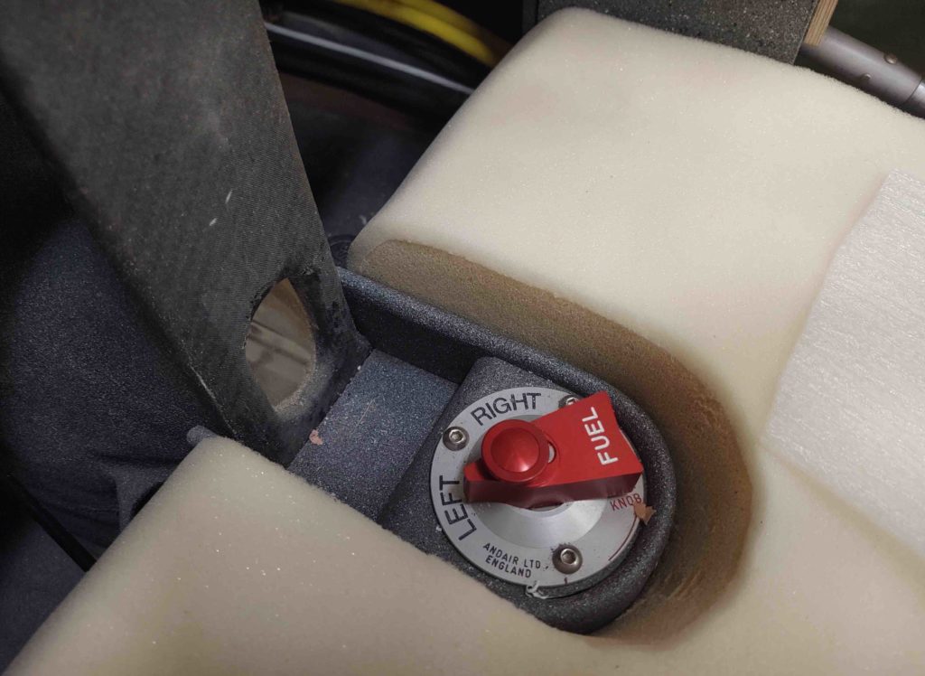
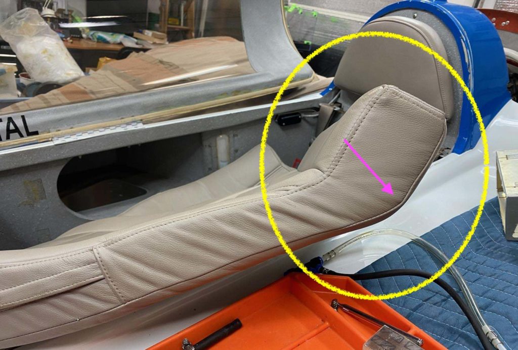
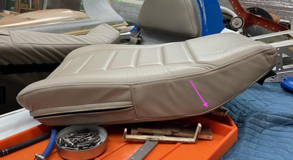
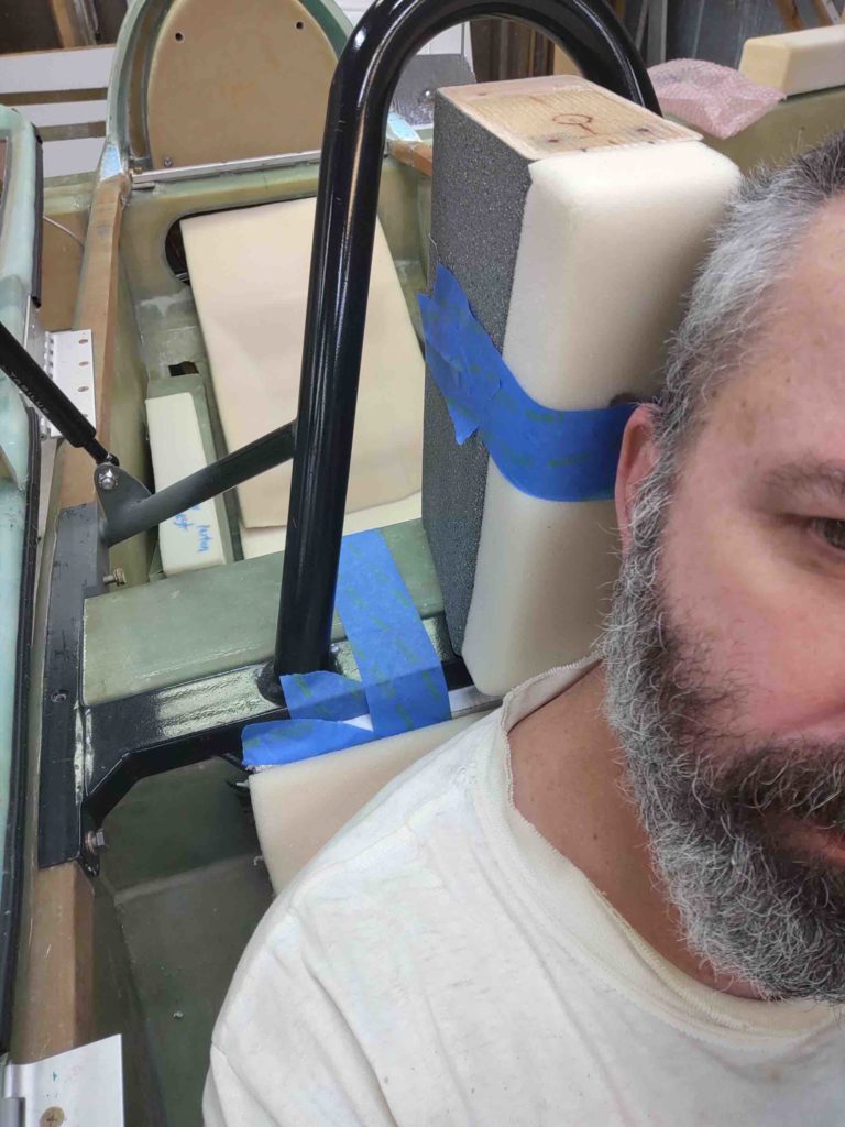
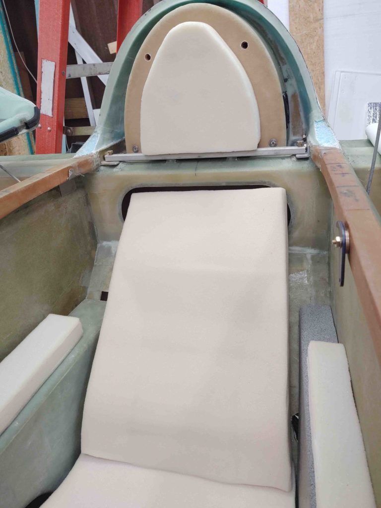
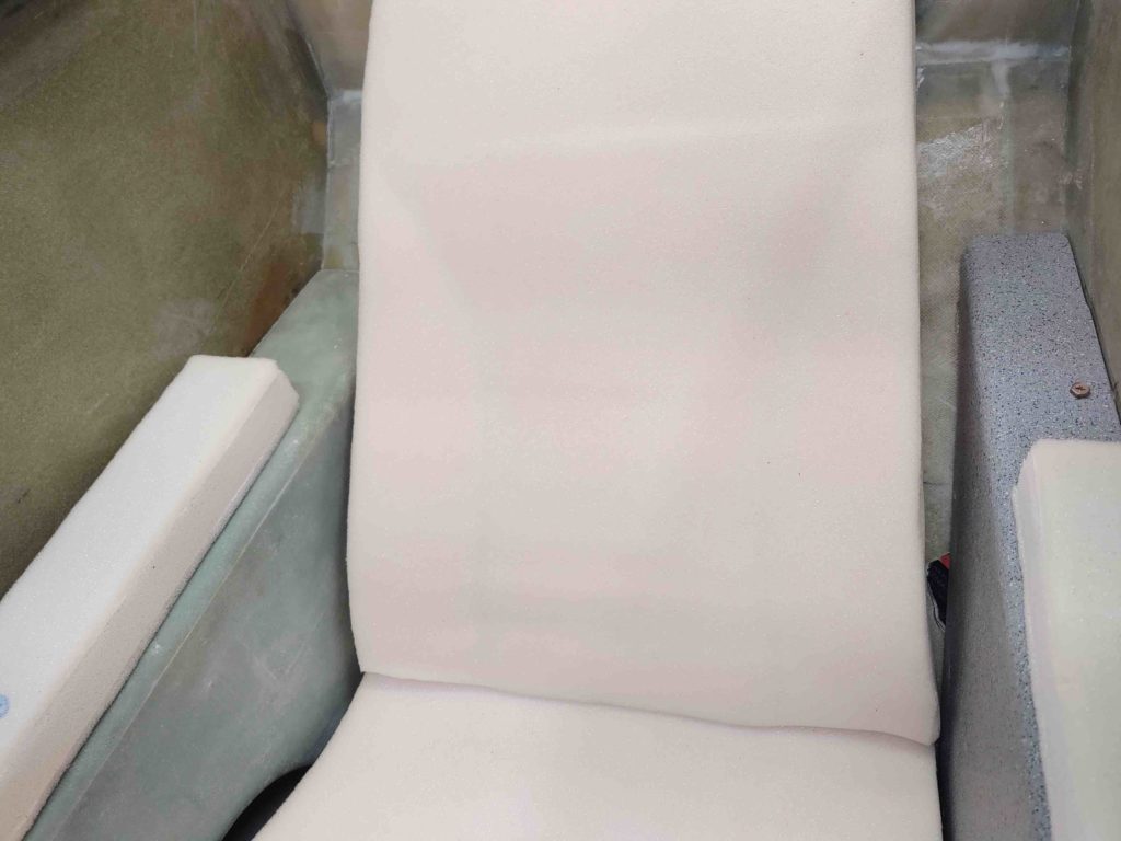
First off, wanted to let ya’ll know that I spent well over an hour compiling all my seat core notes and pics and sent them off to Lisa at Oregon Aero. Over the ensuing days she conferred with Alice who then spent an hour with me on the phone today going over all the seat core mods that need to be done.

I have some homework to do on them: a couple of fit checks and some measurements to take before I pack up the cores and send them back to be tweaked. Should get them out by the end of the week.

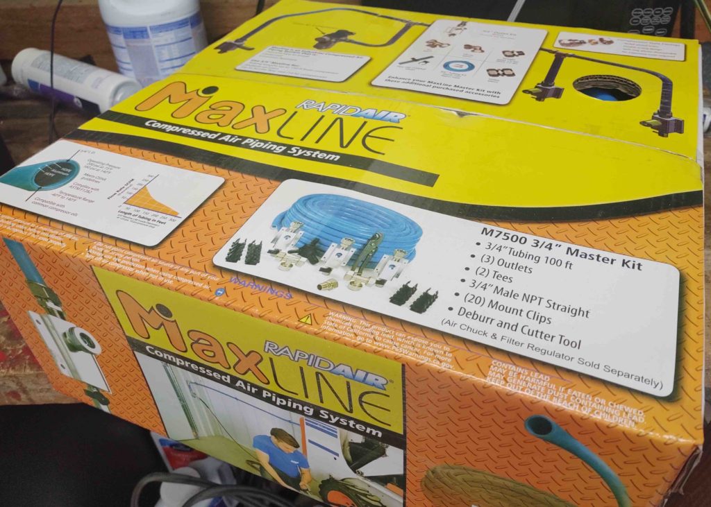
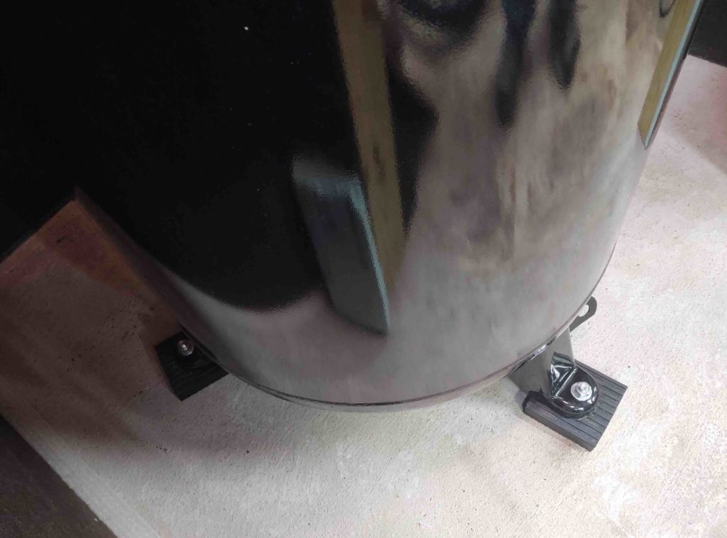
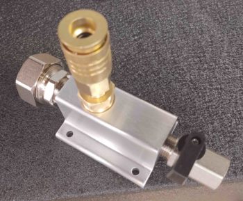
I grabbed a close-up shot of one of the MaxLine kit’s Air Outlet that I’ll have in the center wall at each end of the shop, and also one between the big doors. Each outlet has a water drain. I think they did a great job machining them and they are both well built and good looking pieces of equipment.

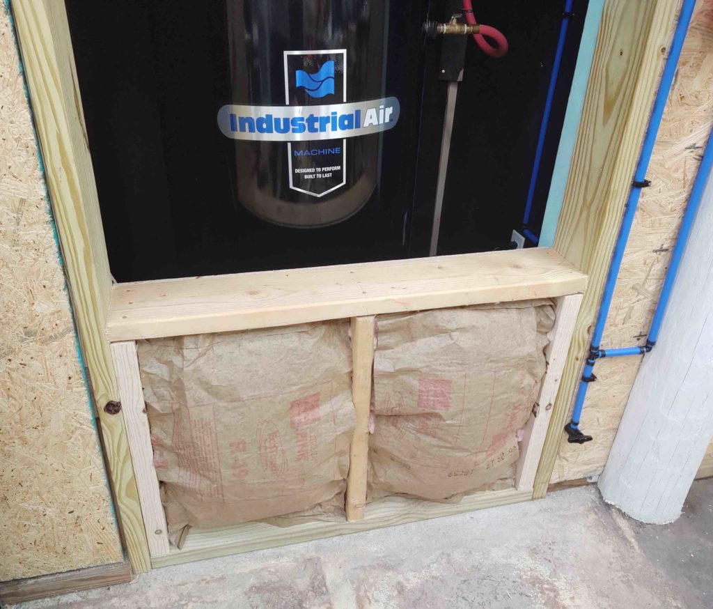
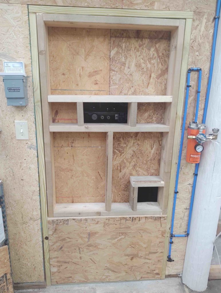
Over the last couple of days I was able to get the air compressor closet door filled in. I started off by adding an OSB panel to the backside of the lower doorway wall. This structure is permanently mounted for the most part and is something that I don’t plan on removing unless I really need access into the compressor closet. It allows for a shorter upper door to help reduce its weight.

I then insulated with 2 layers of 2×6 insulation in each compartment.

And covered the outside with another OSB panel.

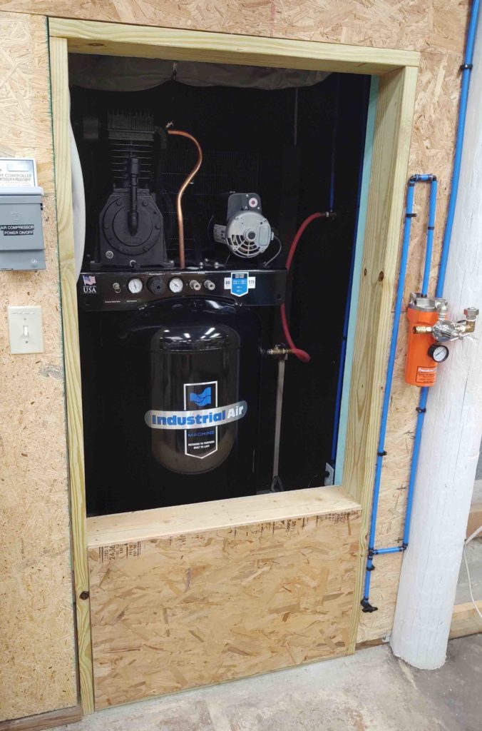
I then framed out the upper door. However, since I wanted the frame of the upper door to be fairly snug in the doorframe itself, I realized that the hinges I had just wouldn’t work. The door is simply too thick to swing into the closed position as a regular door would. Thus, I have relabeled it from compressor closet door to “hatch,” since there will be no hinges now.

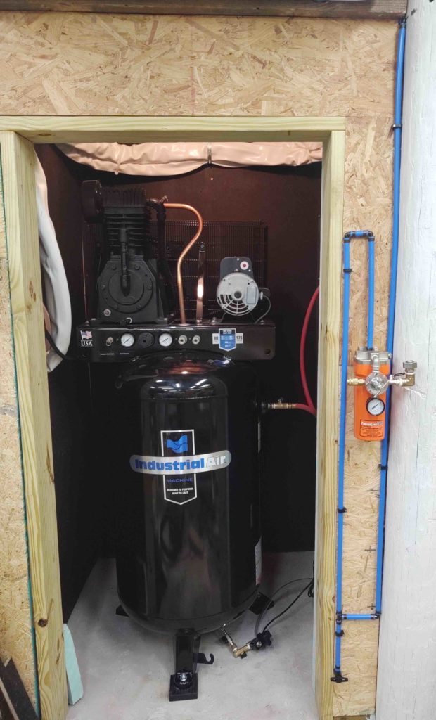
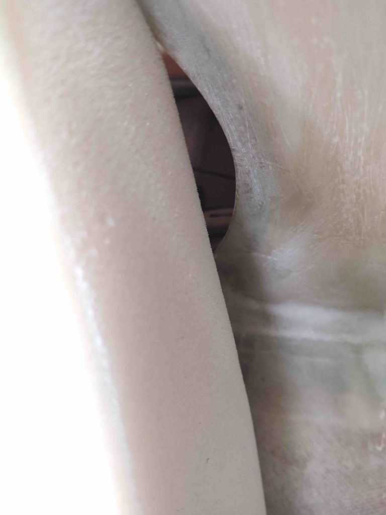
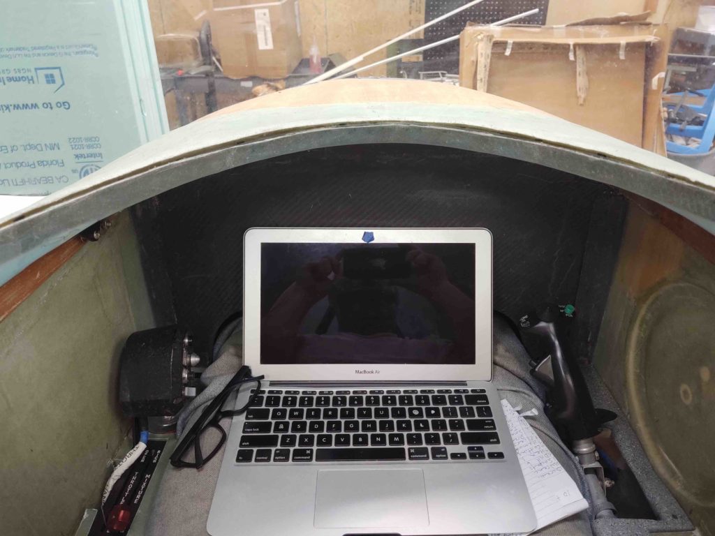
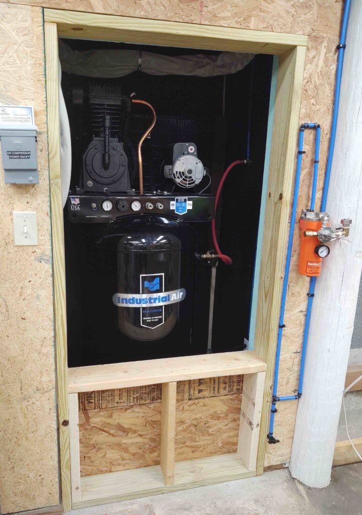
I had planned from the very beginning to build in a window to allow me to gain access to the compressor’s controls and view the gauges. And although most likely rare, I can also connect 2 more air hoses up to the compressor front hose ports if need be.

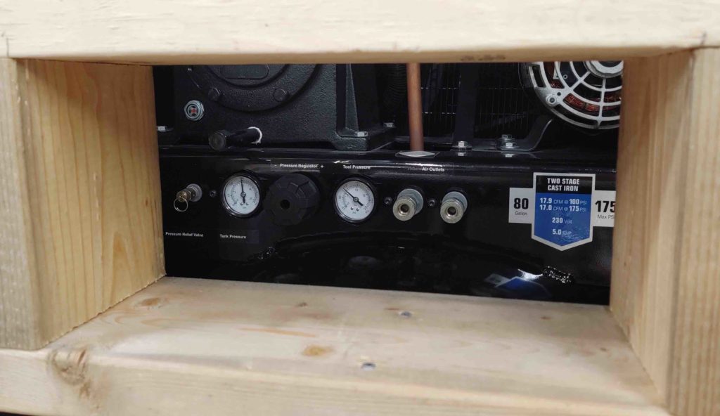
Below is what I see looking through the small portal in the air compressor hatch.

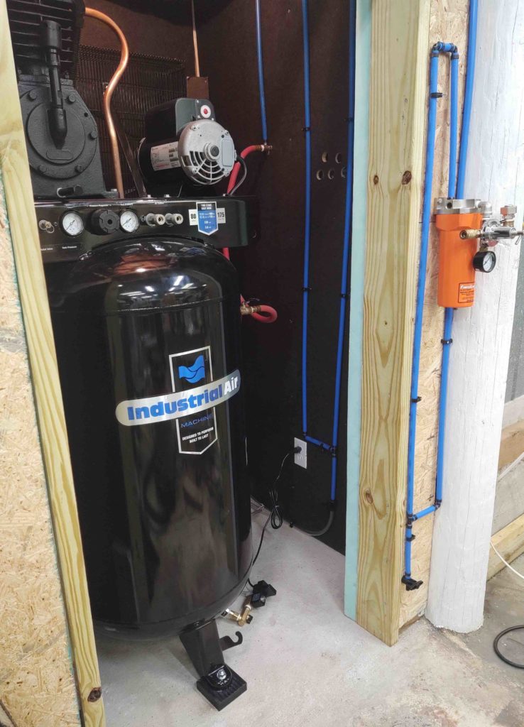
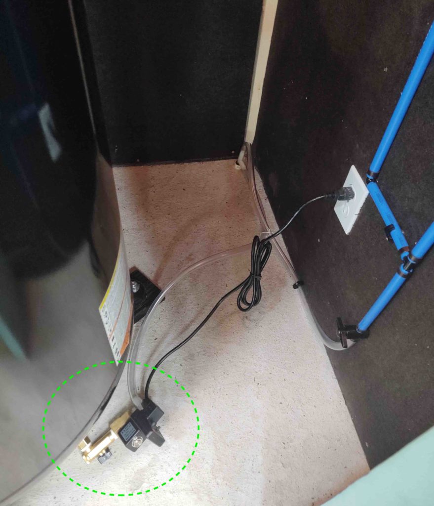
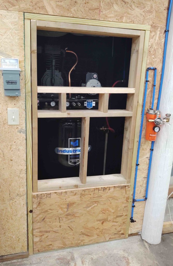
When I put in the air compressor lines, including a water trap inside the closet that has a drain valve, I figured I would simply open the compressor closet door, open the water trap drain valve for a few seconds and then close the door. However, with the door now being a hatch and it being too heavy to remove on a regular basis, I decided to add another small access portal in the lower right corner that is big enough for me to reach my arm into the closet and manipulate the water trap valve.

Below you can see the new lower corner opening framed in, as well as the backside hatch paneling.

As with the lower doorway wall section, I double insulated the upper hatch.

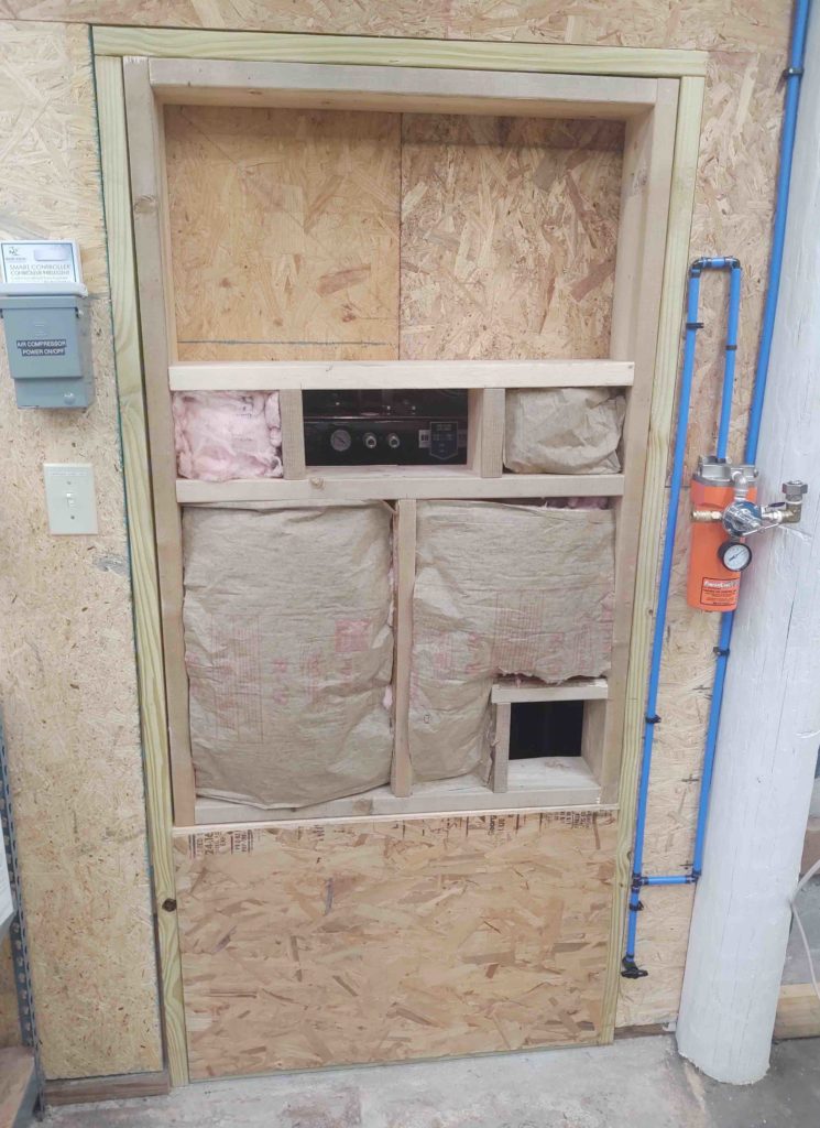
Cut and attached the lower external panel.

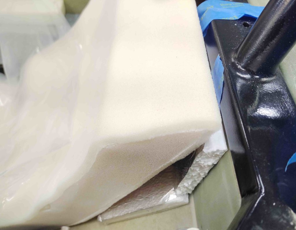
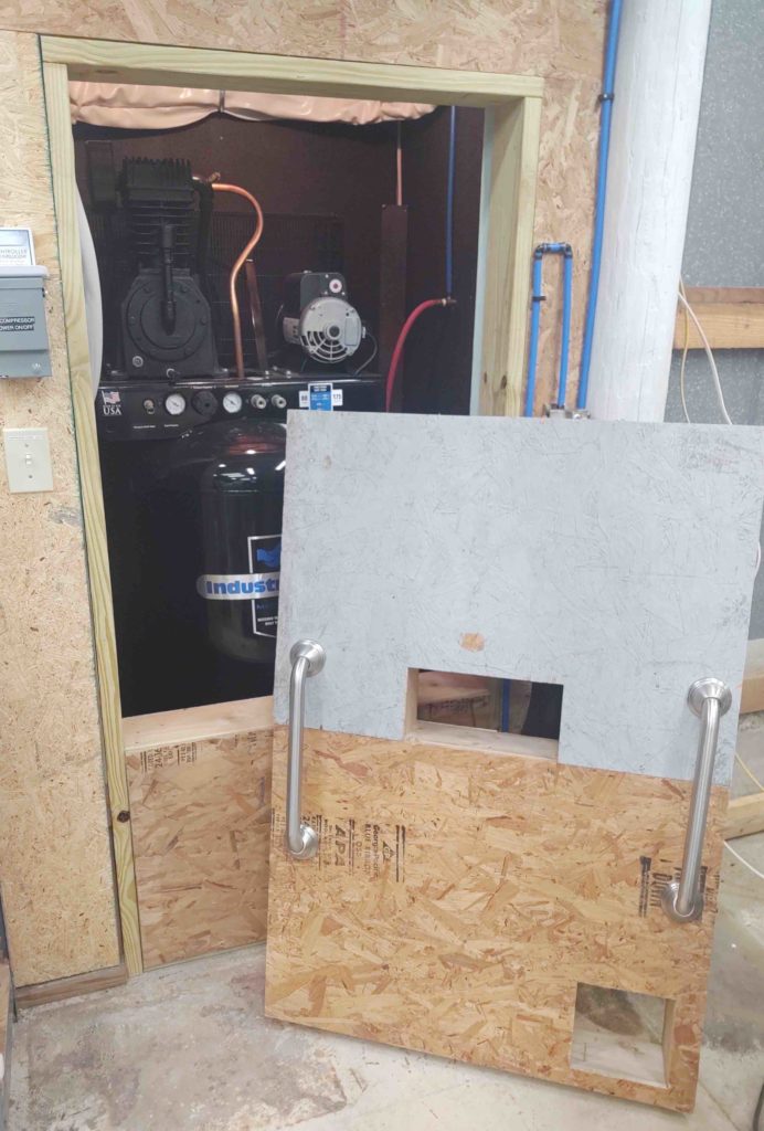
As a point of note, all this OSB is scrap from a bunch of it that I have out under the carport. So here is another scrap piece that I cut to use as the upper panel to the air compressor closet hatch. Also note the view of the compressor control panel through the center portal. These hatch openings will be filled with thick foam to minimize the sound of the compressor.

You can also see that I repurposed two stainless steel handles that I pulled out of the house to use to pull the hatch open and replace it when it’s time to button it up.

The hatch is quite heavy, but not too heavy to occasionally remove it to change the compressor oil and perform any other required maintenance.

With the hatch mounted I did fire up the compressor and checked the noise level. One foot away from the hatch I got a max dB level reading of 70 dB. The average though was around 67 dB. When I moved 6 feet from the hatch the noise level dropped greatly to 55 dB. Clearly the noise will be notable when the compressor kicks on, but will be very acceptable and not ear-splitting when it does. Moreover, I expect those noise level numbers to drop quite a bit once I get the openings filled with foam plugs.

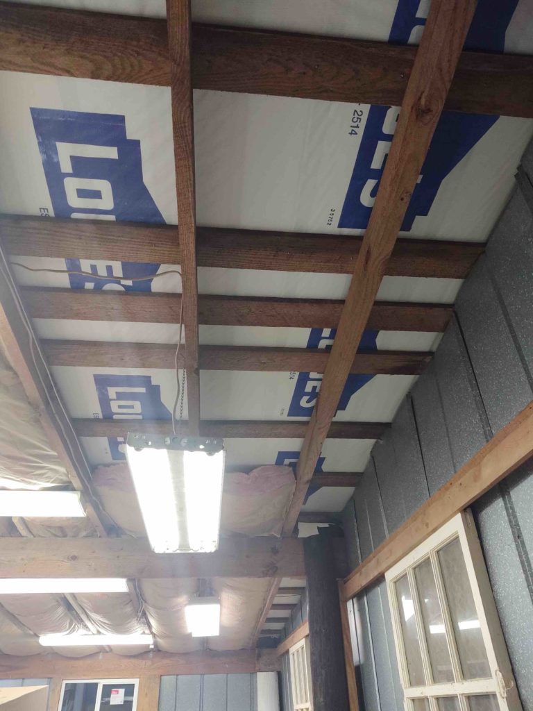
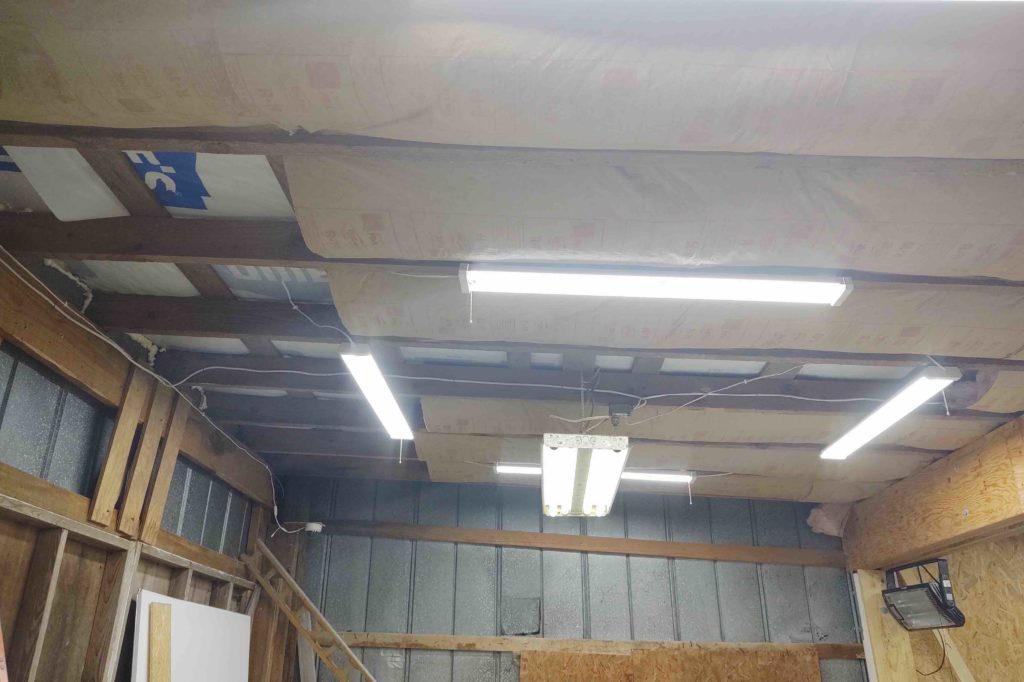
Tomorrow I hope to get the shop air hose conduits installed so I can then move onto insulating the walls and covering them with OSB panels.

Tooling Up – Air Compressor Install

Yesterday and today I focused mainly on getting the air compressor positioned inside the air compressor closet, while also finalizing the design and configuration of the workshop’s compressed air system.

Besides figuring out where I would need the air hose couplers situated throughout the shop for decently optimized access and workability, I also had to account for ridding the air lines of excess moisture (quite common both in the south and near the coast) and ensuring it is dry for both my current tools, and any future tools I may acquire (wink, wink).

As for configuring the shop for access and connections for compressed air, I’m using RapidAir’s MaxLine air system piping kit from Northern Tools.

To facilitate moisture removal, I created two up/down air line water traps prior to the first point of contact for the above air line kit. The first water trap is in the compressor closet while the second one is just to the right of the compressor closet door, where it then terminates into a large filter/moisture extractor/regulator (orange thing).

Note the tubing legs extending down at the low points to collect any moisture in the lines. At the end of each line is a valve to remove any water in the lines.

I also installed an on/off valve on the side of the compressor tank where the air exits into the shop compressed air line system.

Following the manual, I drained a bit of oil in the nearly completely full motor to the required level as denoted by the small glass bubble window on the lower front of the motor. I then fired this baby up and let ‘er run for a good half hour with the side valve open (I wired it up yesterday and very briefly turned it on just to check that the wiring was correct).

I also installed the auto-drain to remove any water in the bottom of the compressor. This should greatly help extend the life of this compressor tank since I’m not as vigilant as I should be in draining my compressors after use! I set the timer for the max time, about 45 min, and was actually pleased to hear it kick on unexpectedly as I was working elsewhere in the shop.

As you can see, I ran clear water drain lines both from the auto-drain and the interior closet water trap that tie into a plastic “T” fitting that I then placed into the drain pipe at the corner of the compressor closet.

Here are two of the three compressor feet, sitting on their respective rubber vibration dampening pads and secured in place by 1/2″ bolts.

After getting the compressor bolted in place, I then turned it on to see how long it would take to go from 0 to the labeled 175 PSI. Well, it fell just a bit short of its mark by making it just above 160 PSI (fine with me) but in a very impressive time as it took only 5 minutes to fill up.

I then finished up the evening by completing one more task of installing my shop air hose reel to the center pole. In addition to the air hose coupler on the orange filter canister and the one on the end of the hose reel, I’ll have one at each end of the shop on the center poles, and one more at the front of the shop between the big bay doors.

Again, starting from the orange filter canister, the shop compressed air line system will get installed as shown by the dashed blue lines.

Tomorrow I’ll continue to knock out as much as I can on the air lines and workshop to in order to get back to work on the airplane build ASAP!

Chapter 26 – Seat Core Check

Ya’ll better sit down for this!

Today I actually did something airplane build related. Yep! Something that has been on my list of things to do for quite a while (along with a few hundred other build tasks, eh?!) … function testing the Oregon Aero seat cores.

Ok, so today was all about the front pilot seat. I plan on doing another stint in the back seat within the next day or two.

Clearly I have a bit of time left on this build. Moreover, with the current state of the world and the Corona virus situation I figure I can wait a few weeks or so before shipping my cores back to Oregon Aero for tweaking and then another subsequent test fit.

In my mind, seat core configuration boils down to comfort, fit and style… really in that order as far as importance goes. I’ll get to style way down the road with color choices and seat material, whereas today’s assessment was definitely focused on comfort and fit.

First off, I know Oregon Aero deals with a lot of orders, and the process of tweaking one’s cores by sending them back for redo’s clearly helps ensure getting what you want at the end of the process. So this isn’t to dog them out, but they did miss one of my initial requirements to taper the front of the pilot seat core down to pretty much a sharp point.

Why?

Feedback from all my EZ-flying buddies, who ALL highlight the whole “heel-catching” syndrome if the pad is too thick at the front of the seat. Sure enough, when I egressed my cockpit today after spending well over 1.5 hours in the seat, the heel of my shoe caught the pad on the way out and flipped it over backwards [I’ve actually been pondering having it made so that one side flips back to then allow for me to plant one heel on the then bared thigh support . . .]. Thus, front seat edge reconfig is definitely on the to-tweak list.

I will say that the seat is definitely very comfortable. I’d also say there’s a significant difference between just sitting in one spot with no movement and no piloting actions (distracted brain usage) vs the real thing. I did notice that all that time sitting in one spot I could feel it my hips a bit, so I’ll play around with maybe putting a thin pad in just the flat section of the seat pan to see if that configuration helps a bit on the long term sitting position.

Another issue I have for both the front and back seat, is that the seat core back is essentially just simply a flat piece of foam, at least as configured here. But both the front and back seats have a vertical component to them as shown here with the front seat back….

and the CS Spar making up the top vertical section for the GIB.

In comparison, here’s a shot of Marco’s front seat pad, and at the top you can clearly see a dogleg.

Marco also snapped a shot of his back seat core for me, showing it too has a dogleg designed into it… unlike my seat cores (currently!).

Since I was stuck in one spot for a while, I figured I’d grab a selfie of my crusty mug for my blog to show the FAA that I’m the guy actually building this darn thing.

Also a shot of the headrest. It too will need some tweaking since, although nice and comfy, it is a bit too ever-present and needs to be reduced in thickness by about half.

Another shot of your’s truly with the canopy closed. I will say (again) with that oversized canopy that I don’t get any sense of being cramped or claustrophobic at all.

I did get a fair amount of computer work done (on the last blog post too) and took notes on some of my seat and cockpit configurations.

The pic below is after I ripped off the headrest pad to see how the front seat sitting felt without it. It was then I realized that it needed to trimmed down by about half in thickness (1.8″ to 0.9″ thick).

I was also querying Marco via text on his seat configurations, visibility, etc. So this shot below is at my eye level and pretty close to exactly what I see out of the front of the canopy with the current seat core as it is.

On the inside I can see about the bottom 2/3rds of the longerons where they dive into the panel on each side. With a lowering of my head or a slight tilt, I can easily see the entire top of the panel all the way around.

Here’s a shot of the back seat, which I know I took when I first got the cores. To be honest I’ll sit in it a bit just to check it out again, but until another 2″ gets added to the top of seat back core I don’t consider anything a valid fit test. As you can see, the top of the seat core simply falls into the oval storage opening in the CS Spar.

One last note on the back seat cores that I’m going to check with Oregon Aero on is the required width of the cores. The front seat seams fairly snug with a bit of wiggle room for the final upholstery. However, the back seat cores seem to have a good 5/8″ gap on each side of the bottom pad, and even more for the top pad.

Obviously tweaks need to be made, so I don’t want to take away from how very comfortable these seat cores are. Clearly I have plenty of time to tweak them, so I will at a minimum get my notes collected and documented, and then the cores packed up ready to be sent back to Oregon Aero for some refinements.

Tooling Up – Shop ceiling insulation

Yep, still dealing with necessary “evils” . . .

Over last couple of days I’ve been able to knock out nearly all the insulating of the underside of the workshop roof (aka ceiling!).

Below is what was left to do at the right end of the shop (Bay 3) when I started today. The strip along the wall will remain unfinished until I get the wall insulation and covering in place, which will give me something to attach the insulation to.

And here we have the ceiling insulation situation over the front (entry) portion of Bay 1.

And here’s the Bay 1 ceiling a few hours later. I still have two half strips to do to finish up all the workshop ceiling insulation except the strips along the sidewalls.

Here’s the same area as the first pic above, just taken from a side angle. With the ceiling insulation pretty much finished I can now really start in on finishing up the walls.

I also plan to start slowly mixing in some minor airplane build tasks here within the next week or so!

Tooling Up – Final workshop roof

Yes, more updates on my workshop (sigh… ) and although it probably seems like the following task is purely a cosmetic one, I can assure you that it is more about preventing rainwater from weaseling its way in under the roof panels and collecting on the underlayment (trapped in between) . . . not good!

First off, this step of the finishing the roof isn’t happening at this point since I am now just getting around to it! I ordered these corner edge caps and materials in mid-December. The local building supply seriously just got all the components to me a couple weeks ago! Their buffoonery would make for a laughable sitcom episode if this was TV, but it’s not and in real life it was simply a maddening version of Abbott and Costello’s “Who’s On First” skit.

So of course after a good two weeks went by my schedule and the weather finally jived enough for me to get around to installing the roof edge caps.

Here’s the right end of the carport that was done almost a week before the front was completed (complete with fresh paint underneath).

Here’s the “BEFORE” shot of the front edge of the workshop roof. As you can see, in the meantime I had installed some security cameras on the corner of the workshop (need my tools and toys to be secure while I’m out of town!).

And this is a couple of days later when I completed —finally!— the workshop’s new roof install.

Here we have the top part of the workshop roof front edge corner cap. You can see how it covers the first 6 inches of the roof panel to keep the rain OUT.

If you look closely in the pic above, about mid-point of the roof front edge, you can see the junction of where the back yard meets the large concrete tarmac in front of the workshop. The dirt and grass piled up along this junction is where I dug about an 8-inch deep trench to run two outdoor CAT 7 ethernet cables from the “IT Closet” inside the house. One of these cables provides Internet/WiFi to the workshop while the other one is for workshop’s interior/exterior security cameras. Previous to running these cables I was just too far out of range to receive a good WiFi signal from the house.