Chapter 25 – Bottom left strake micro

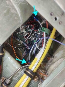
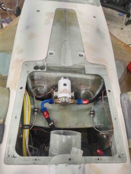
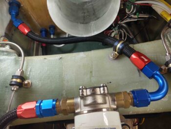
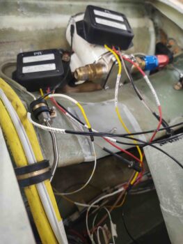
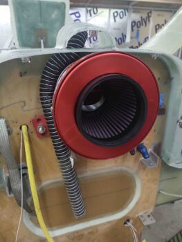
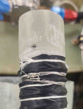
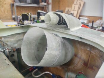
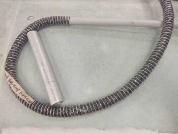
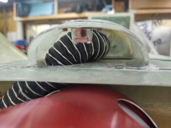
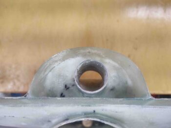
I started off today by finalizing my requirements for the engine compartment oil lines and fittings, and also a replacement 30° fitting for the OUT side of the oil heat pump (its alignment is off a bit with the current straight fitting pulling/stressing the hose to one side), before pulling the trigger on an order from Summit Racing.

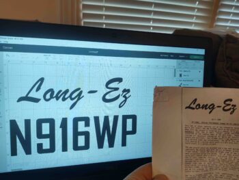
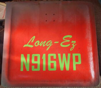
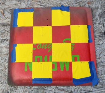
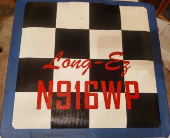
I then spent about an hour assessing and finalizing my trim paint design on the bottom of the fuselage, and as it flows back onto the cowling.  I will be tweaking it so I’m not showing it here since I know some things will change on it.

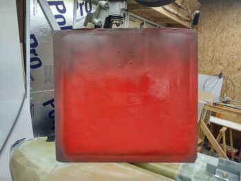
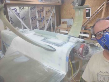
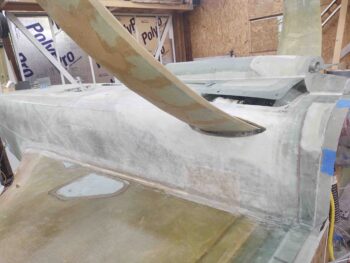
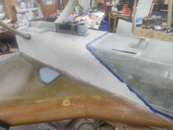
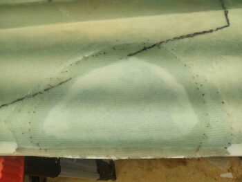
I then got to the major task at hand for the day: micro finishing the left strake bottom surface.

I started with about an hour of sanding the surface dull.  I will say that I plan on following yet another piece of advice from Wayne Hicks and that is to peel ply the surface on the top strake skin layups so I don’t have to mess with this incessant crazy sanding.

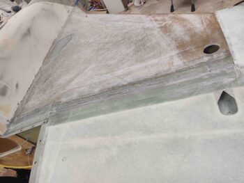
I vacuumed and cleaned up the major sanding dust with Simple Green, then wiped down the strake with acetone.

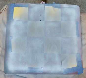
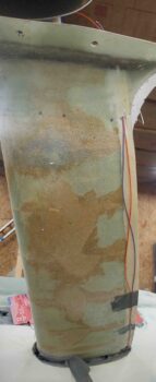
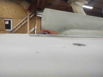
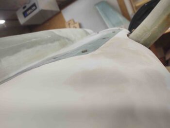
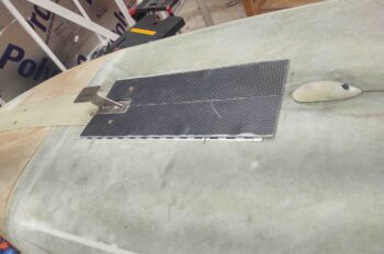
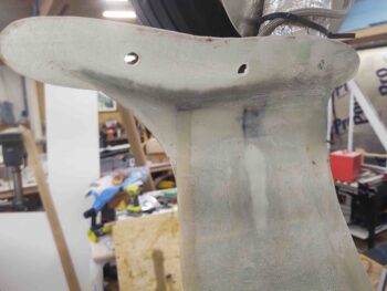
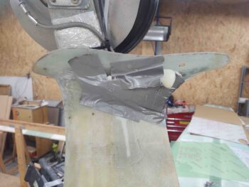
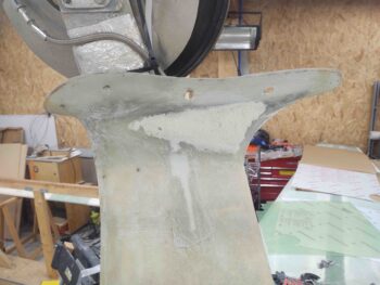
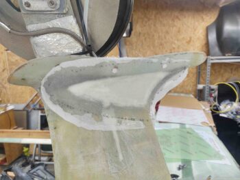
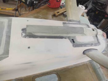
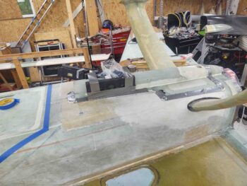
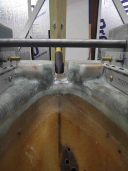
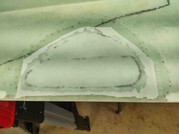
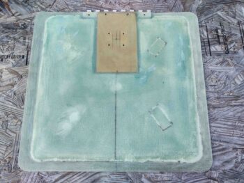
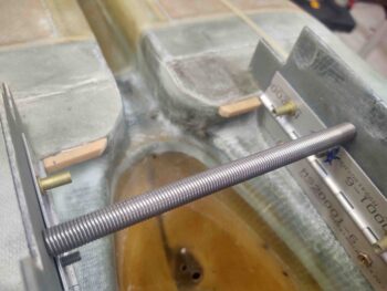
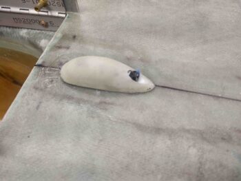
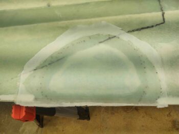
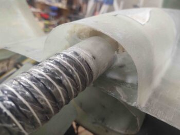
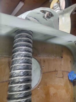
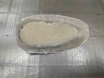
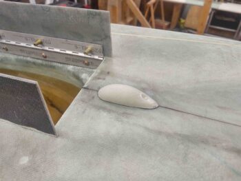
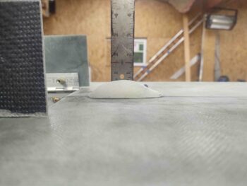
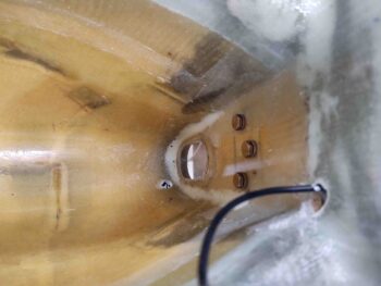
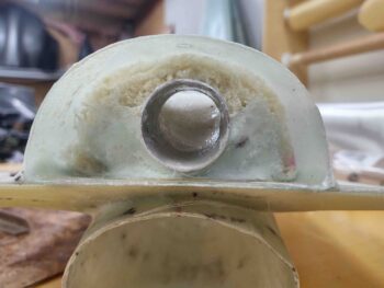
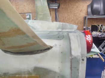
After taping off the strake’s boundary I mixed up some flocro with some fast hardener (West 205) and applied it around the interfacing perimeter edge (wing and bottom cowling) of the strake.  As you can see, I applied it thick and about an inch wide.

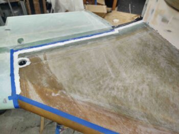
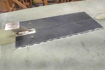
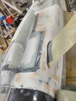
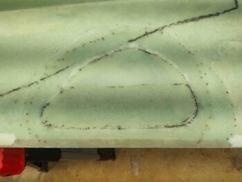
I then whipped up my micro/410 mixture… a bit heavier on the West 410 this time (about 50/50).  Remember, I want to learn all I can about micro finishing these planes, so the bottom of the plane is what I consider my experimental playground.  Thankfully this stuff just works, and it really isn’t overly finicky.

Case in point: after I finished there was a bit of it stuck to the un-sanded surface of the wing, and I can tell you it did not just pop off and allow itself to be removed without a fight. This stuff STICKS with any reasonable modicum of preparation.

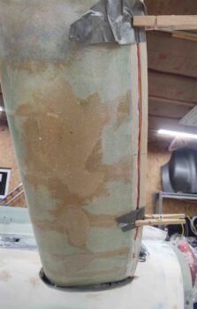
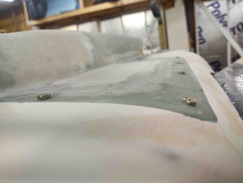
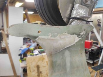
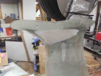
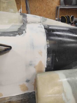
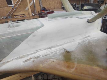
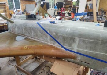
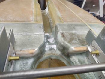
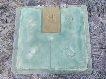
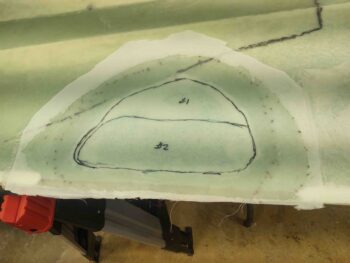
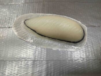
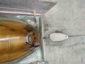
I should note I started the strake fill from the front inboard corner to provide the flocro edge as much time as possible to cure and harden.  I used slow hardener (West 206) for the main fill, and sure enough, by the time I got to the outer perimeter the West 205-based flocro was fairly cured.

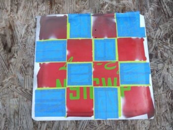
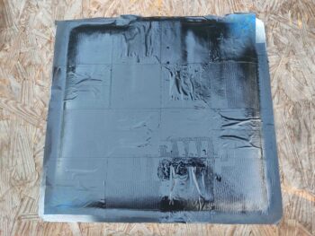
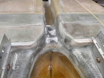
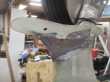
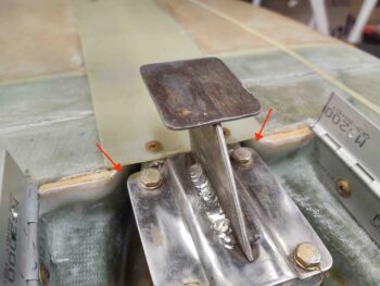
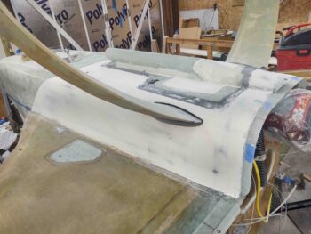
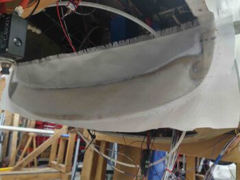
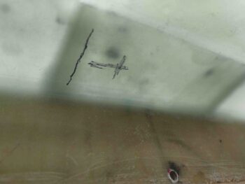
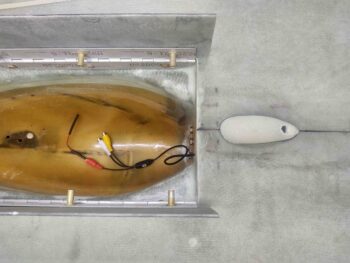
I then pulled the tape from around the flocro edge to expose nearly all the seam between the strake and wing.  The black Gorilla duct tape tabs are a fail-safe to ensure I didn’t lose the seam so I can get a hacksaw blade in there to clean it up when it all cures.

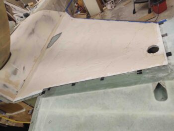
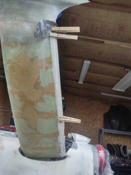
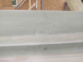
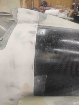
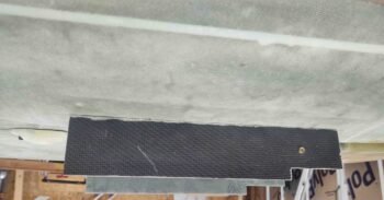
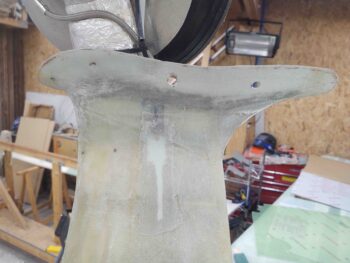
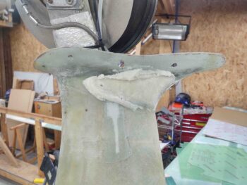
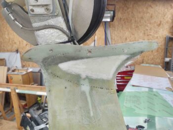
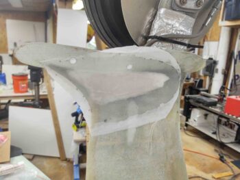
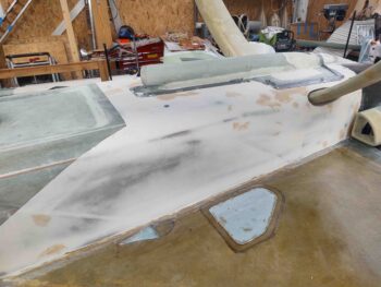
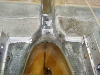
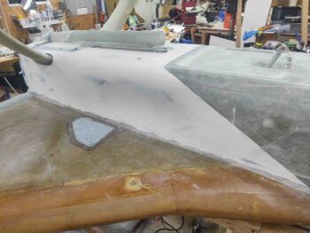
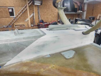
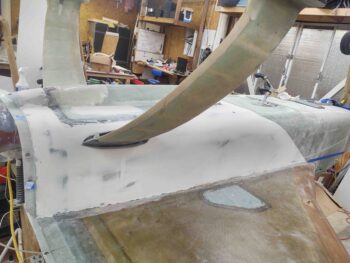
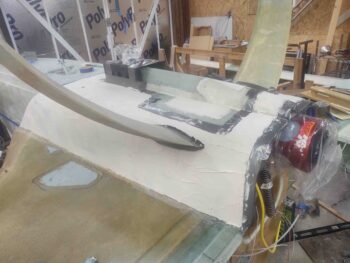
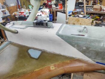
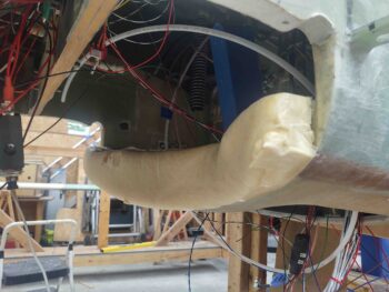
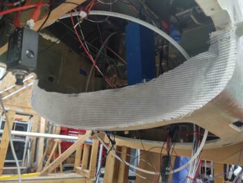
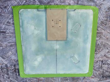
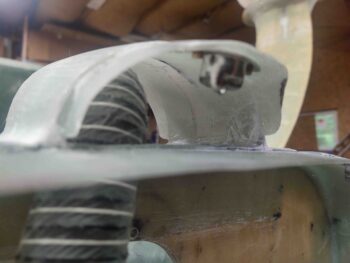
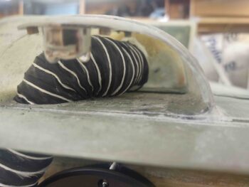
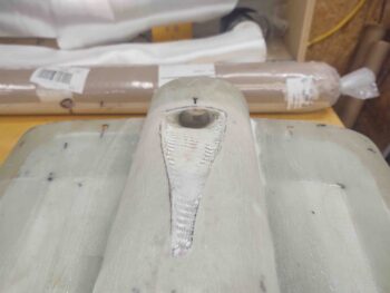
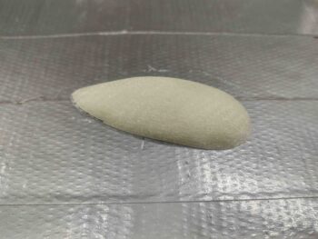
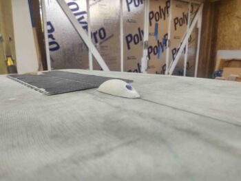
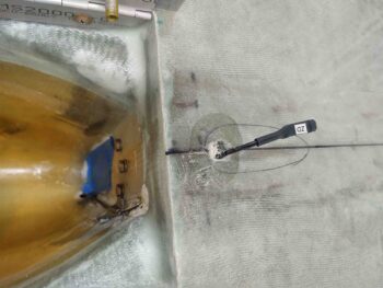
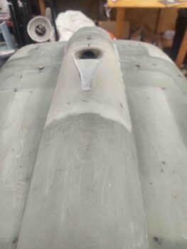
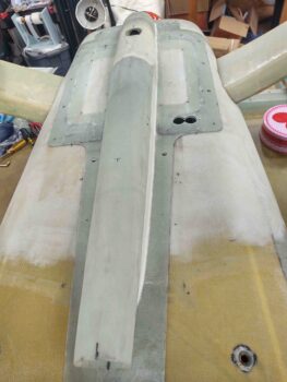
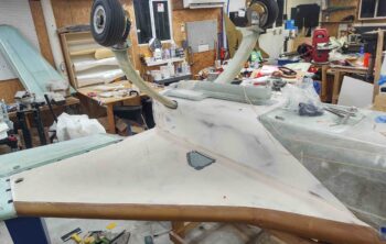
Here’s the micro/410 finished left strake bottom surface from the front.  I realized when I grabbed this shot that I needed to remove the front leading edge tape.

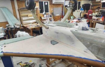
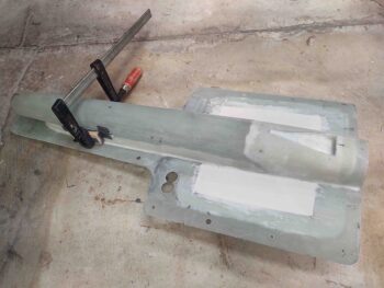
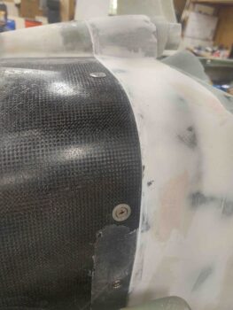
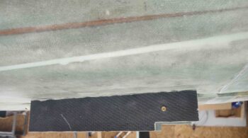
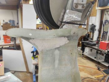
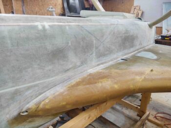
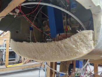
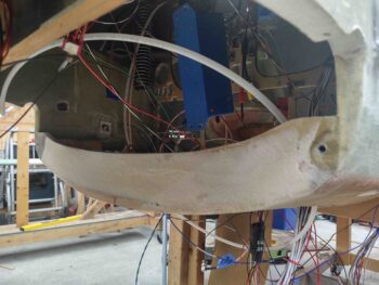
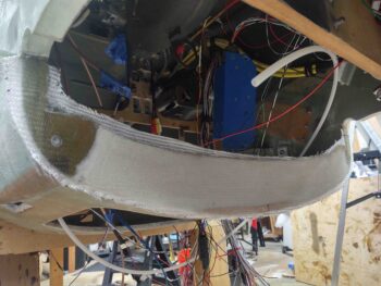
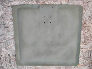
Which I did here.  I then left this applied micro to cure overnight.  The ridges are fairly small and I’ll knock them down with the air sander, so I’ll note I’m not overly concerned with cheese-grating this micro after it nearly fully cures.

Tomorrow I plan on doing the right strake in pretty much the same fashion.  Although I may try 100% West 410 on that surface to see how it does (still using a flocro edge of course).

Chapter 21/22/25 – Secret Projects

So I’ve recently been working on a couple of projects that I didn’t highlight until I knew they were a go.  I call them “secret” projects, but the reality is I didn’t want to take the time to blog about them if they ended up being fails, or undoable.

I actually started project #1 shortly after I primed the landing brake interior surface. I had seen a pic of an RV with checkerboarded flaps and really liked the look of it, so I wanted to incorporate some type of checkerboard theme on my landing brake.

I decided I wanted a checkerboard background with red text in the foreground, so I had to figure out how to accomplish it.  I decided to actually lay the red down first, then apply the text over the red before painting the checkerboard.

I was trying to figure out how to apply the text, and then Jess lent me her Cricut to cut out some vinyl to use as a reverse stencil, if you will (thanks hon!).

Note the cursive text I’m using for the “Long-Ez” label is nearly identical to the cursive text on some of the plans.  I’m not overly fond of the cursive, but it’s a bit historic and symbolic of that era, so I’m happy to have it as part of the scheme.  And of course it does help set it apart from the plane’s N-number.

Jess got me a pack of permanent red vinyl, but I thought I would try out using the background red paint first. Then if that didn’t work out well I could use the red vinyl as a backup option.  So I went out and picked up a variety color pack of temporary (vs the permanent) vinyl to use as my reverse stencil.  I chose green and then cut out the letters.

As you can see below I then applied the letters onto the landing brake.

I then used some other yellow protective vinyl –no, those are not post-it notes– to mark off what will be the black blocks of this simplified checkerboard.

I started out with a couple of coats of light gray primer.

Then of course forgot to get a shot of the white paint laid down.

After the white cured I then covered up those blocks, with the final bit of red background showing.

And then gave the exposed blocks a few good coats of black.

Later in the evening I pulled the protective tape from the white blocks, then carefully removed the lettering vinyl.  BTW, the blue tape on the border represents the blue that I will paint the airplane trim, and this border.

I still have a good bit of touchups to do, but being that it’s the landing brake and will be under the plane, I’m not looking for perfect… I’m looking for FUN and DONE!

“Secret” Project #2 is running a pair of 22 AWG wires down each gear leg… on the top side trailing edge in the micro trough.

I first of course had to make sure it was doable, which obviously it turned out to be.  I have a few ideas of some thing(s) that might get mounted in the wheel pants, and just in case I decide to go for it later on I wanted to have my electrical wires pre-run while I have “access” to do so.

I first measured out the required length for the wires: 48″ each side, and cut them.  I then drilled the top hole (as situated) into the micro channel and under the securing wheel pant skirt glass.

Over a couple of days I carved out a bit of time each day to Dremel a small trench in the trailing edge micro and then micro the wires into the trench.

I then peel plied the micro.  Here you can see the right gear leg wires are embedded and almost completely encased in micro.

I did a few of other small tasks on my list as well.

I drilled a couple small holes in a delam on the side of the RAM air scoop, syringed some epoxy into the delam and then clamped it up.

Later in the evening I pulled the clamp off and all looked good.  However, when I was sanding some of the excess epoxy off the delam the bottom half of the glass tore out and I was left with a half-repaired delam.  So I simply sanded the cured epoxy on the other half and called it good.

I also tightened up the AN fittings per specs on the fuel line in the hell hole.  I still have to secure the line to the fitting coming through the firewall, but that will be finalized after I put the metal firewall covering in place.

Lastly, after reading a tale of woe in a CSA article about a builder not being able to run his rudder cables through the conduits many years after building his wings, I ran a long piece of wire through ALL the rudder cable wing and fuselage Nylaflow conduits to test that they were clear and unobstructed.  Thankfully they were, so I can put that little check behind me.


Chapter 25 – More fuselage finishing

Today I removed the CAMLOCs and screws securing the RAM air scoop/hell hole hatch cover to the bottom of the fuselage.  I also removed as much of the protective edge tape as possible.

Then, as carefully as possible, I popped off the RAM air scoop/hell hole hatch cover from the bottom of the fuselage.  I had to give it quite a sharp rap from the front side to dislodge it from the serious grip the raised micro edge had on it.

I then inspected the micro edge and cleaned it up a bit.  Of course I have a few spots that need filled and/or repaired, but overall it looks great and I’m very pleased with it!

I then cleaned up the RAM air scoop/hell hole hatch cover before re-mounting it to the bottom of the fuselage.  It went back on nicely and barely got hung up on the micro edge, just a very minute bit of fiddling to get it back in place.

I then tried to get some pics to show the elevation of the bottom fuselage finishing micro as compared to the RAM air scoop/hell hole hatch cover surface.  Of course I still have to micro finish the RAM air scoop/hell hole hatch cover so some dialing in on the surface levels will be required.  But again, I’m very pleased with how this came out.

Here’s a shot looking aft along the right lower “corner” of the fuselage.

In addition, in these pics you can see where I had lightly sanded over the entire aft fuselage micro finish West 410 repair patches.  Not that I doubted Wayne Hicks in any way, but he nailed it again with using straight West 410 for repairing scratches and filling the big holes… it sands level very nicely.

And a shot looking forward from the left side, right near the firewall.

I then spent a bit of time cleaning up the junction at the firewall-to-bottom cowling where I slathered in some flocro to fill some gaps and clean it up.  I need to add a bit more flocro in the junction gaps behind the armpit scoops, and level out the surface elevation between firewall/bottom fuselage and cowling.  I’ll do that by adding a bit of micro to the front edge of the cowling and fair it level with the firewall area micro finish.

Again though, it looks really good and I see no issues moving forward whatsoever.

I then reinstalled the freshly trimmed nose gear doors and tested out the fit and look of them.  Here’s a couple shots of the doors in the closed position… which look way better IMO!

And then another couple shots where I inverted the pics to show how they would look on the bottom of the plane…. again, much, much better looking to me!

And with my baby-step successes in hand for the day, I called it a night!

Chapter 9/13/24 – Landing gear tweaks

I started off today quickly pulling the peel ply, razor trimming the overhanging glass and hitting the corners with a sanding block on the nose gear wheel well front wall extenders. They look good and may need some very minor tweaking in elevation for the gear doors to rest against, but I’ll evaluate that when everything is back together.

I then got busy knocking out yet another prerequisite task before I flip the plane back upright: filling the depression on each gear leg just above the wheel paint skirt on the inboard side.  Grant it this depression was created by adding the small fairing on the aft side, and the slight off angle between this fairing and the gear leg.

In my armchair engineering mind, for air to flow smoothly here and not get all burbled up, I need to fill these respective depressions and smooth out this junction.  In addition, I plan on finishing the bottom of the gear legs very soon and want to get as much done as possible on the underside before flipping the plane back over.

Here are the before shots.

I then cut a small triangular-shaped duct tape-covered cardboard dam and taped it in place. Once in place I snuck some pour foam in behind the dam.

Here’s the resulting pour foam addition to the bottom inside of the gear legs.

I then shaped the foam on each side…

And laid up a single ply of BID over the foam… after micro’ing the foam.

I then peel plied the layups.

I have to say I’m very pleased with these tweaks and with a little micro think they’ll really clean up these bottom gear legs and allow the airflow to be “trip” free.

I then got back to work on the aft/bottom fuselage.  To fill in the deep scratches and divots I followed Wayne Hicks advice and simply used West 410 “micro” mixed into West epoxy all by itself.  I had intended to use fast hardener, but forget and used the slow instead… no big deal of course.

The 410 worked great and was pretty much smooth and creamy as you would expect from something like Evercoat’s Metal Glaze to be… however, having read the warnings in the CSA articles I want to stay away from any application that is NOT epoxy based.  I prefer my airplane’s finish to be as bubble free as possible, thank you much!

I had a decent amount of 410 (as par usual) left over so I actually filled in a bunch of the smaller holes as well… why not eh?

I remounted the bottom cowling with the lower front edge taped up to allow me to apply a flocro edge to the firewall area/cowling intersection micro finish on the lower fuselage. There were some gaps, chips and low spots that of course needed filling in, so I figured flocro would give me a nice hard edge that would be less prone to chip or get dinged as I removed and mounted the bottom cowling over the upcoming years.

I then left the repairs and added flocro to cure overnight.


Chapter 13/25 – Finishing aft fuselage

I started off this morning by lowering the nose gear (as positioned, inverted) into the nose wheel well to check the clearance between the nose wheel assembly and the newly attached wheel well wall extenders (red arrows).  As you can see, there was plenty of clearance.

That cleared me hot to go ahead and glass the top of the wheel well wall extenders and then peel ply the layups.

Not shown is a small layup I did on the front foam piece of the taxi light pocket and also another ply of BID on the bottom outboard delam repair on the right wing…. I’m hoping that’s the last added ply of BID that needs to go on there.

With my wheel well wall extenders looking good, and with no clearance issues with the nose gear, I proceeded to mark the very front tab on the nose gear doors for elimination…

Which I did here.  I think removing these tabs will really clean up the nose gear doors and make them look much cleaner, and much, much better.

I then got busy sanding the micro I had applied to the aft/bottom fuselage. I took this pic for Terry Lamp when he shot me a text to see if I was at Oshkosh… nope, sanding away in the shop!

Here’s just a small sample of the mess I made . . .

And some cleaned up shots of the micro removal process.

An overhead shot of the sanded micro.

And a couple more side shots.

I won’t be micro’ing up the middle of the fuselage until I get the landing brake prepped and mounted back in place, so I expect it to be a few days.  In the mean time, as I’m working on the landing brake, I’ll also continue to do some sideline tasks that are on the list to be completed before the fuselage can be flipped back upright.  In addition, I’ll start sanding the bottom airplane surfaces for the upcoming micro finish.

Chapter 25 – Frosting the cake!

Yesterday was all about researching and refining my processes for micro’ing up the plane to finish it for paint, so no shop work except for prep.

Today I finished sanding the aft & bottom fuselage in prep for micro.

I want to get the firewall, RAM air scoop/hell hole hatch cover and gear leg areas finished right off the bat so that I can dial in those surfaces, primarily to then create the top-of-gear fairings at their intersection with the fuselage.

I then plan to move forward on the fuselage and outboard to the strakes and wings on my micro’ing endeavors.

After I finished the sanding I then vacuumed and cleaned up the surface.  I then taped up all the various surfaces I didn’t want to get micro’d.  I also taped up the front edge border where this round of micro will end, as you can tell by the blue tape.

Here’s the micro finish prep on the left side with the blue border tape in place.

I then got busy micro’ing up the aft/bottom fuselage.  I know some people will think I’m crazy, but I want to try out different techniques and mixtures on the bottom of the plane for the experience and knowledge of applying various types of micro and the varying techniques in doing so.  Thus, for this area I actually mixed in the West 410 filler at about a 4:1 ration with regular micro just to see how it sands in comparison to straight West 410 micro.

I mixed up the micro fairly dry and it was the typical pain to get it to stick to the surface of the fuselage… the saving grace being the heated trowels that I was swapping out, as I re-heated them by resting them on the edge of one of my heat lamps pointing straight upwards.  The heated trowels really were the trick, along with hard pressure in multiple directions, to getting this crap on in a somewhat reasonable fashion.

As a point of note: I basically worked the micro thickness as it stated on the side of the West 410 filler container, “dry peanut butter.”  In other words, I mixed it to a consistency that was a difficult pain to apply, but not something so ridiculously dry that it was nearly impossible to get it on there.

After I got all the micro on where I wanted it, I then removed the blue border tape since the micro was already starting to set up fairly quickly.

After the micro had cured for a few hours and was in the “green” stage I cheese-grated the high points and ridges to make it easier to sand tomorrow evening when it hits the 24-hour cured point.

Yep, the adventures continues!


Chapter 13/19/24 – Prepping for finishing

I started out the day adding yet another ply of BID to what was the delam on the outboard bottom side of the right wing.  The delam is now gone, but I still have a bit of a depression from all the foam that was removed along with the micro and glass when it delaminated.

I had peel plied the layup and thought I took a pic of it, but only had this shot much later in the evening when I removed the peel ply.  Still, I’ll be adding at least one more ply of BID to this repaired delam to get the divot to an acceptably filled in level as compared to the surrounding wing surface.

I then glassed the nose wheel well front wall foam extensions (about 1/4″ deep) with 2-ply BID layups over dry micro fillets on the bottom and inboard edges.  You may also note the micro I filled in on areas down the nose gear strut channel.

Tomorrow I plan on trimming the overhanging glass and then creating small flox edges front and aft as I lay up a ply of BID on the top of each of these foam extensions.

Moving on.

Part of my laundry list of tasks to complete before the bird gets flipped back upright was the front face of the F28 bulkhead.  If you recall, I poured this foam when the fuselage was vertical while I was flipping it inverted.

This task is actually a recent add to my to-do list, when I realized that it would save a lot of cleanup from all the foam and dust from going into the airplane if I simply did all the work now.  Thus, I first took a standard wood saw and cut off the initial majority of the foam.

I then took about 20 minutes to shape and sand the foam flush on the face of F28 (pic #1).

I then traced out a quick cardboard template to allow me to cut the single ply of BID I then laid up on the face of F28, after applying micro to the foam of course.

I then wetted out the BID (pic #1).

And then peel plied it (pic #2).

I then spent a good hour cleaning up and organizing the shop and clearing off a bunch of stuff from the strakes and wings in prep to sand the plane’s bottom glass surfaces for micro.

I then sanded a good bit of the bottom left fuselage in prep for micro finishing.  But it was late so I called it a night before finishing the other side.

Chapter 19/22/24 – Hell hole antics

I started off today adding another 2 plies of BID to the right wing bottom outboard delam repair.  Yes, the crater is still a bit more depressed than I want (or the plans call for) so I decided to slowly add to the thickness and re-evaluate.  I laid up one full ply inside the depression and then another “half”-sized ply towards the trailing edge.  I then peel plied the layup.

I really want to get all things on the bottom of the plane completed and not have to mess with them once the plane is back upright.  Part of this is the interior paint (first) on the landing brake.  I have some ideas on what I want to do, but first I had to get the landing brake off the plane….

Wow, talk about sins of the past coming back to bite us.  I guess I didn’t ever think this landing brake would need to be removed, so it was a bear getting it off… about an hour of pain and sweat!

Obviously I finally got it removed.  I sanded it to rough up the surface then gave it a good wash with Simple Green.  I then used some Metal Glaze to fill a number of small holes in the surface of the landing brake (pic #1).

I then measured and marked the perimeter border of the landing brake (pic #2).

I then taped off the perimeter border with painter’s tape.

I hit the interior area with a few coats of primer.

In between the coats of primer on the landing brake, I constructed the final oil heat line hose to connect the oil heat pump feed from the firewall fitting, that is itself connected on the other side to the engine oil sump.

Moreover, to secure this newly added hose I floxed and glassed a clickbond on the bottom of the gear strut to then mount an Adel clamp.  Here it is quite a few hours later after the clickbond glass had cured.

I then spent a couple of hours installing the fuel tank probe control heads into the hell hole. I started by finalizing the wiring configuration and labeling, then soldering the wires into the hell hole.

After connecting and wiring up the fuel tank probe control heads, I then physically mounted them into the hell hole on their respective mounting pads.

It was getting late, but I wanted to get a couple more tasks knocked out.

First I cut and 5-min glued a pair of foam tabs onto the front wall of the nose wheel well. These tabs, once secured via glass, will provide a hard stop for the front edge of the gear doors.  Not the current front edge mind you, but in fact will allow me to trim off that first tab jutting out very conspicuously… reducing the number of “steps” from 3 to 2.  I think this will drastically improve the appearance of these gear doors.

Finally, I spent a few minutes sanding and filing the inside of the micro’d hole on the aft side of the bottom centerline video camera mount housing.  I then cut a slot on the forward bottom (as situated) to run the camera and cable up into the housing.  After a few test fit iterations, with subsequent rounds of sanding, I was able to get the video camera slid up into the mount housing.  Again, I’ll secure both camera and the cable inside the nose wheel well once I hook the system up and position the camera view correctly.

I expect to have maybe one more day of working these prerequisite bottom-fuselage tasks before the priority will shift to sanding/micro’ing/finishing the bottom surfaces of the plane and working these tasks in-between the micro applications during the curing times.

Chapter 13/19 – 2 huge tasks complete

Today I got 2 really big tasks knocked out in my quest to get the bottom of the plane finished to allow me to flip it back upright.

First was a delam on the outboard bottom trailing edge area of the right wing that I discovered when I pulled the wings out to cut the aileron pockets.  I have been pondering on exactly how to fix it, but since I have not dealt with a delam this big before I knew I would need to dig into the plans to help guide me on the how-to.

And I’m glad I did.  I discovered that any delam larger than a couple of inches in diameter need much more of repair than just shooting raw epoxy under it and weighing it down. According to plans Chapter 3 the glass needs to be removed, the edges feathered back, and new glass laid up in the same bias as the original glass, with an overlapping ply of BID.

Yes, I had to then go to Chapter 19 to double check the direction that the plies of UNI were laid up on the wing.  About 30° each ply as per below.

I then ID’d the edges of my delam as best possible, and marked the offending area for removal.

Then I grabbed my trusty Fein saw, took a deep breath, and then cut a large chunk out of my wing skin.

I then laid up the 1st and 2nd ply of UNI in the approximate orientation as the Chapter 19 diagrams shows, overlapping out onto the feathered glass a minimum of an inch (yes, the plans show 2″… I made a call here).  I then covered the UNI plies with a ply of BID that went out beyond the UNI a minimum of a half inch.

Planned anyway. My BID went a little wide, and not so tall, but it stilled covered the UNI and all looked good.

I then peel plied the layup.

Late in the evening, with the layup fairly cured, I then marked up the peel ply with subsequent plies of BID required to help back fill this large divot I had just created on my wing.

You see, it doesn’t seem like removing the top layer of 2 plies of UNI should make that much of crater in the wing, but when it takes all the interfacing top surface of foam that is secured to the underside of the skin with micro, that’s a good 1/8″ of material gone.  I suspect I’ll need even maybe another round or two more plies of glass to fill in this area.

Huge task #2 was getting my nose gear doors working so that when they open up as the gear is lowered, both doors are vertical and parallel to each other.  In their current state for the past 5+ years, this has not been the case.

A serendipitous discussion with my Long-EZ building buddy Brian Ashton, and a few pics and measurements he texted me, was just the trick I needed to fix this long-nagging issue. I explain what I did and discuss it in a video I made here:

With these tasks out of the way, I’m getting much closer to sanding and micro-finishing the bottom surface of the bird in prep for paint and flipping it back upright to continue on with my topside build tasks.

Chapter 22/23/24 – NACA scoop glassed

I started out today by cleaning up and trimming the engine NACA scoop connector that is the interface between the NACA’s aft fitting and the SCAT tubing that carries the air into the engine compartment.

I then test fitted it into the 1.25″ SCAT tubing… so far so good.

And then test fit it on the NACA aft fitting.

It’s a go!

With that piece of the puzzle out of the way, it was time to proceed with getting the SCAT tubing ran from the aft fitting on the NACA scoop into the engine compartment, via the firewall bridge.  The idea here is simple: drill a 1-3/8″ angled hole through the flange on the aft bottom side of the firewall to run the SCAT tubing.  My goal was to get the hole as close to the inside edge of the firewall bridge as possible, to allow as much clearance as possible between SCAT tubing and the RAM air can.

I then drilled the 1-3/8″ hole using a step bit.  It came out nice.

After cleaning up the edges of the hole I then test plumbed my SCAT tubing… again, so far so good.

A shot of the SCAT tubing entering the firewall bridge.

I then tested out connecting the SCAT tubing to the NACA scoop aft fitting… it’s tight, but doable!  I’m really glad that I didn’t go with the 1.5″ tubing since I don’t think it would have worked.  There’s just not enough space in these tight quarters for any larger SCAT tubing.

I then re-installed the RAM air can as the final checkout to ensure there was clearance between it and the NACA scoop’s SCAT tubing.  There’s just enough clearance for both to coexist and not impact the functioning of the other…

With the physical connections tested out, and the NACA air routing plan a go, I proceeded to glass the inside of the NACA scoop with a ply of BID, in 2 pieces: one on top and one on bottom, overlapping a bit on the sides.

While the NACA scoop glass cured, I then used my ClampTite tool to secure the SCAT tube connector into the forward end of the SCAT tubing.  Note that I secured the wire band of the SCAT tubing under the wire clamp.

Here’s the final position of the NACA scoop’s interfacing SCAT tube connector, residing in its home in the firewall bridge.

Later, once I get all the firewall components in their final configuration, I’ll make up a “Y” fitting that splits the NACA scoop air into 2 paths via 1″ SCAT tubes to respectively cool the mechanical engine-driven fuel pump and the PMAG electronic ignition.

I had poured foam into the fuselage bottom centerline video camera housing earlier and finally got around to trimming & sanding it down to be even with the backside surface of the housing.

I then marked the housing for trimming.

And then trimmed off the backside edge and sanded the surface of the video camera housing.

I then drilled a 3/8″ hole on the aft side of the video camera housing and tested out its position on the bottom of the fuselage, just aft of the nose gear doors.

As I mentioned before when I used the original S-glass nose bumper nub as a mold, I didn’t need the video camera housing to be as tall/deep as the bumper was… here the profile is just under 5/8″.

And a shot of how much the video camera housing will protrude in flight.

I had already drilled a 3/8″ hole [the size of the camera lens, since I have to route all the cabling in reverse due to the pre-wired connectors] at an angle from the bottom fuselage surface into the nose wheel well, and here I’ve also drilled a 3/8″ hole in the top right aft edge of the nose wheel cover to route the bottom CL fuselage video camera cables.

Since I don’t know the required clocked position of the camera for it to display a nice horizontal/upright shot on my EFIS, I need to wait until I get the EFIS installed and fired up to do the final mounting of the camera.  However, to secure the cable in place, but still keep flexibility in positioning/rotating it, I used pour foam in the drilled cable channel.

Here we have the bottom CL fuselage video camera cable & connectors exiting the nose wheel cover, and ready to be connected to the video camera multiplexer.

After I confirmed fit and configuration of the bottom CL fuselage video camera housing, I created small flox corners around the perimeter of the backside and then glassed it with a ply of BID.  I then peel plied the layup.

This shot is clearly a number of hours later after I pulled the peel ply and trimmed the layup.

I then slathered in some micro around the edges of the video camera mounting hole for a nice appearance and transition.

After a good bit of video camera shenanigans, I then got back onto the mostly cured NACA scoop layup.  I had laid up the glass going into the aft fitting tube to keep the glass transition as smooth as possible.  Here I’ve just trimmed the glass at the aft edge of the aft fitting.

I then test fitted the trimmed, sanded and cleaned up NACA scoop as I set the RAM air scoop/hell hole hatch cover back in place.

Here’s a longer shot of the NACA scoop on the RAM air scoop aft structure.

And a profile shot of the NACA scoop on the bottom aft side of the RAM air scoop structure.

I had to do some minor trimming and sanding to make the interfaces nice and tight again, but after some minor fiddling the fit was good.

I then added some more micro around the top (as positioned in the pic) of the NACA scoop aft fitting and then glassed a ply of BID in over the bare foam.

And with the NACA scoop pretty much complete and the interface fits good, I left this layup to cure and called it a night.