
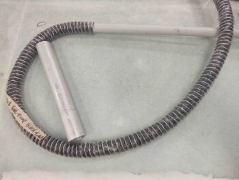
I started out today by cleaning up and trimming the engine NACA scoop connector that is the interface between the NACA’s aft fitting and the SCAT tubing that carries the air into the engine compartment.
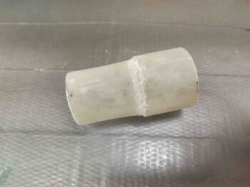
I then test fitted it into the 1.25″ SCAT tubing… so far so good.
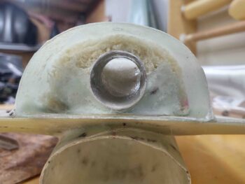
And then test fit it on the NACA aft fitting.
It’s a go!
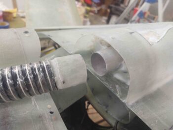
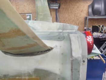
With that piece of the puzzle out of the way, it was time to proceed with getting the SCAT tubing ran from the aft fitting on the NACA scoop into the engine compartment, via the firewall bridge. The idea here is simple: drill a 1-3/8″ angled hole through the flange on the aft bottom side of the firewall to run the SCAT tubing. My goal was to get the hole as close to the inside edge of the firewall bridge as possible, to allow as much clearance as possible between SCAT tubing and the RAM air can.
I then drilled the 1-3/8″ hole using a step bit. It came out nice.
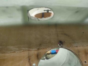
After cleaning up the edges of the hole I then test plumbed my SCAT tubing… again, so far so good.
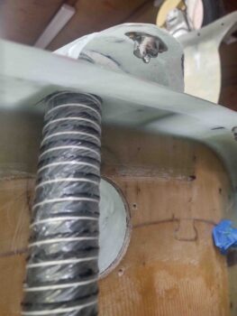
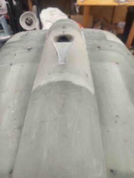
A shot of the SCAT tubing entering the firewall bridge.
I then tested out connecting the SCAT tubing to the NACA scoop aft fitting… it’s tight, but doable! I’m really glad that I didn’t go with the 1.5″ tubing since I don’t think it would have worked. There’s just not enough space in these tight quarters for any larger SCAT tubing.
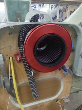
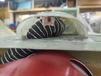
I then re-installed the RAM air can as the final checkout to ensure there was clearance between it and the NACA scoop’s SCAT tubing. There’s just enough clearance for both to coexist and not impact the functioning of the other…
With the physical connections tested out, and the NACA air routing plan a go, I proceeded to glass the inside of the NACA scoop with a ply of BID, in 2 pieces: one on top and one on bottom, overlapping a bit on the sides.
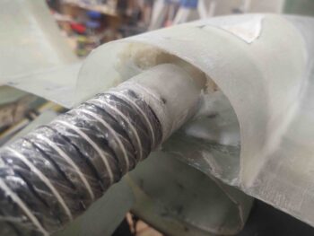
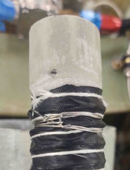
While the NACA scoop glass cured, I then used my ClampTite tool to secure the SCAT tube connector into the forward end of the SCAT tubing. Note that I secured the wire band of the SCAT tubing under the wire clamp.
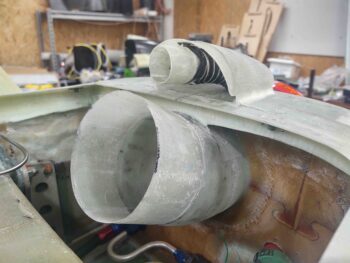
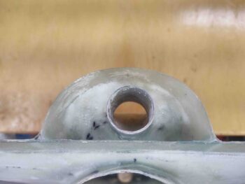
Here’s the final position of the NACA scoop’s interfacing SCAT tube connector, residing in its home in the firewall bridge.
Later, once I get all the firewall components in their final configuration, I’ll make up a “Y” fitting that splits the NACA scoop air into 2 paths via 1″ SCAT tubes to respectively cool the mechanical engine-driven fuel pump and the PMAG electronic ignition.
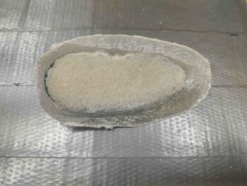
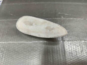
I had poured foam into the fuselage bottom centerline video camera housing earlier and finally got around to trimming & sanding it down to be even with the backside surface of the housing.
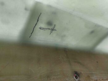
I then marked the housing for trimming.
And then trimmed off the backside edge and sanded the surface of the video camera housing.
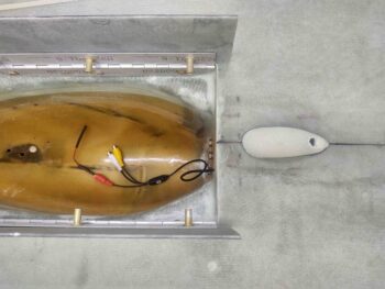
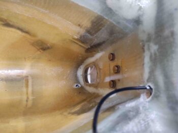
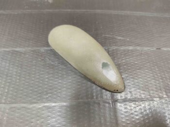
I then drilled a 3/8″ hole on the aft side of the video camera housing and tested out its position on the bottom of the fuselage, just aft of the nose gear doors.
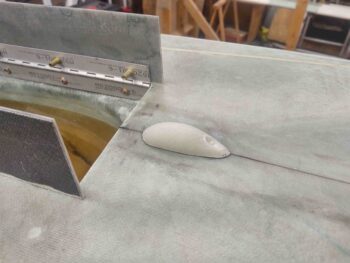
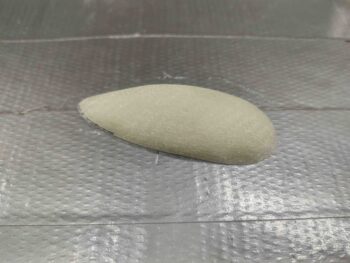
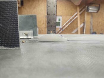
As I mentioned before when I used the original S-glass nose bumper nub as a mold, I didn’t need the video camera housing to be as tall/deep as the bumper was… here the profile is just under 5/8″.
And a shot of how much the video camera housing will protrude in flight.
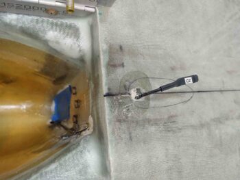
I had already drilled a 3/8″ hole [the size of the camera lens, since I have to route all the cabling in reverse due to the pre-wired connectors] at an angle from the bottom fuselage surface into the nose wheel well, and here I’ve also drilled a 3/8″ hole in the top right aft edge of the nose wheel cover to route the bottom CL fuselage video camera cables.
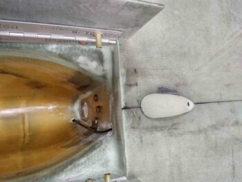
Since I don’t know the required clocked position of the camera for it to display a nice horizontal/upright shot on my EFIS, I need to wait until I get the EFIS installed and fired up to do the final mounting of the camera. However, to secure the cable in place, but still keep flexibility in positioning/rotating it, I used pour foam in the drilled cable channel.
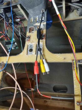
Here we have the bottom CL fuselage video camera cable & connectors exiting the nose wheel cover, and ready to be connected to the video camera multiplexer.
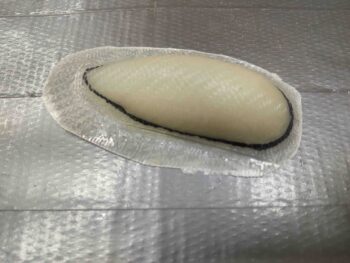
After I confirmed fit and configuration of the bottom CL fuselage video camera housing, I created small flox corners around the perimeter of the backside and then glassed it with a ply of BID. I then peel plied the layup.
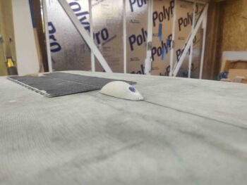
This shot is clearly a number of hours later after I pulled the peel ply and trimmed the layup.
I then slathered in some micro around the edges of the video camera mounting hole for a nice appearance and transition.
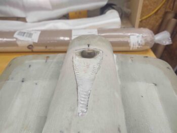
After a good bit of video camera shenanigans, I then got back onto the mostly cured NACA scoop layup. I had laid up the glass going into the aft fitting tube to keep the glass transition as smooth as possible. Here I’ve just trimmed the glass at the aft edge of the aft fitting.
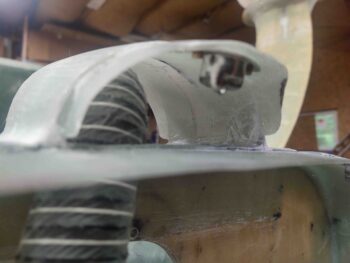
I then test fitted the trimmed, sanded and cleaned up NACA scoop as I set the RAM air scoop/hell hole hatch cover back in place.
Here’s a longer shot of the NACA scoop on the RAM air scoop aft structure.
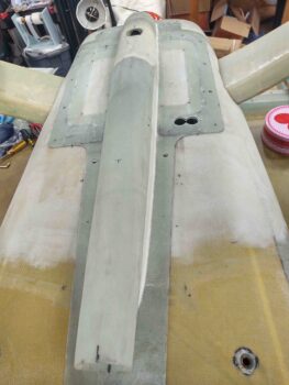
And a profile shot of the NACA scoop on the bottom aft side of the RAM air scoop structure.
I had to do some minor trimming and sanding to make the interfaces nice and tight again, but after some minor fiddling the fit was good.
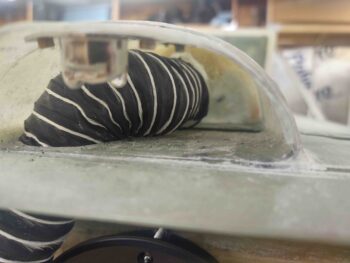
I then added some more micro around the top (as positioned in the pic) of the NACA scoop aft fitting and then glassed a ply of BID in over the bare foam.
And with the NACA scoop pretty much complete and the interface fits good, I left this layup to cure and called it a night.