Chapter 13 /22 – Baby steps . . .

Is all I got done today.

Between some more much needed cleanup/decluttering/prepping for my weekend guest… and having my little munchkin-buddy over for a few hours catching critters and dismantling my initial test pour-foam in a cup (foam cellular structure looked great btw), I didn’t get a whole lot accomplished today.  I called in a couple hours earlier than I normally do and just took it easy.

I did get the fuselage flipped around in the shop, so now it’s positioned nose out.  This to get ready for the upcoming wings-mounting endeavor as a precursor to the strake build.

I also seated, test-fitted and then marked my prototype nose hatch hinge bracket to assess the gap I need for the hinges on each side.  I then marked those and plan to widen them tomorrow.

My little buddy helped me add duct tape to the back of test panel #3 and then temp install it for yet another panel test fit.  I already see a couple minor tweak points (not worthy of a whole new test panel cut btw) but still need to sit in the cockpit to assess fit before going final with the real 0.090″ thick 6061 instrument panel cutting.

I also spent a good 45 min drilling out the ball oiler fittings on the mill’s saddle (X and Y axes’ junction cross-slide) to then tap them to accept the threaded tubing quick-connect fittings.

Below I installed a couple of the tubing quick-connect fittings on the front of the saddle as an example of how these will be installed.

There will be 2 fittings on the front, 2 on the back, and one on each side for a total of 6, on the saddle alone.  Add that to the 2 on the column/Z-slide for a grand total of 8 ports for injecting oil onto the ways and gibs from the One-shot oiler reservoir.

Of course I’m trying to knock out as much as I can on the build, but over the next few days (after tomorrow) my progress will most likely be slim to none.

Chapter 13 – A step forward, and then…

My first task in the shop today was to get a 2-ply BID layup over the nose hatch hinge bracket nutplate assemblies that I embedded with flox yesterday.  I then peel plied the layup.

As the layup cured, I got to work on a hollow stainless steel shaft that I ordered from McMaster-Carr and was just delivered mid-morning.  I’ll be using the shaft as a sleeve over the screw/bolt coming out of each side of the nose hatch hinge bracket, and for the flanged ball bearing press fitted into each hinge to ride on.

The sleeve OD is right at a 1/4″ (0.250″) . . .

While the ID of the bearing is 6mm, or around 0.235″.

I then used the lathe to take down the SS sleeve OD to just under that of the bearing ID.

My parting tools suck, especially on stainless steel, so I just marked the cut line and then used the Dremel as I had the sleeve rotating in the lathe chuck.

Since the last 3D printed test hinge was right in my sight, I grabbed it to test out the bracket-screw-washer-bearing/hinge-nut setup.  Once together, it all worked nicely.

Note the flange of the press-fit bearing (blue arrow).

Here’s a shot from the inside of the bracket, with the countersunk #8 screw head showing.

I then cut the 1/8″ x 1″ 6061 bar stock for the other (left) end of the nose hatch hinge bracket.

I then marked the screw hole to match the right side of the hinge bracket (although I forgot to countersink the hole, which is one reason I drilled the hole prior to welding… argh!!).

I then prepped the hinge bracket for welding.

A bit later, after a horrendous welding session, I test mounted the bracket.  The inside corners were just being really tough to get any good welds into, totally exacerbated by my lack of practice or any recent TIG work.  I simply put too much heat into this aluminum part and actually cracked it as I was trying to bend the slightly heat deformed right side back to vertical.

I then realized that this bracket just became the prototype for proof of concept of my hinge install setup, and that a new thicker (and taller) bracket would need to be constructed (or possibly milled …. hmmmm?).

After loading all my pics I also realized I didn’t get a shot of the finished layup …

On the bright side, I did get a good cut on the plasma cutting table of test instrument panel #3.  I really do believe this will be the last test panel I cut (although I still need to test fit and assess).

Besides some more shaving off of the upper left corner, the biggest change on this panel version is that I moved the ELT remote control head from just above the row of circuit breakers in the lower right corner, up about 6″ to sit adjacent to the Mini-X EFIS.

[Interesting tidbit: There are 4 small pieces that were cut out from the panel that are “welded” to the tops of the slats . . . can you find them?]

Now for some exciting mill news!

I got my hoist all set up and rigged up the mill headstock to get it into position to mount onto the 3 big bolts protruding from the column-mounted Z-slide.

After getting the headstock re-mounted onto the mill, I then grabbed a thick sling and rigged the mill to be hoisted onto the blue base.

Here we are, mid-hoisting . . .

I then slowly lowered the mill onto the blue base and bolted it into place.

The initial front-to-back (Y-axis)  . . .

And left-to-right (X-axis) leveling looked near perfect… until I tried the Y-axis on the right side.  It was off a bit, so that made the entire leveling outcome a big compromise to get all sides within specs…. which are my specs, btw.

After an hour of shimming all around, I got the mill base (not the blue pedestal) dialed in so that the level bubble was within the big solid lines.  All had a scant more gap on one side of the bubble than the other.  But remember, this level is SUPER sensitive, and about the thickness of sheet of paper (or less) will move the bubble back into exact center. Unfortunately, one low corner knocks the whole leveling endeavor into a wonky compromise.

With that, here’s the mill in its current state.

Another shot.  Note that I also mounted the Z-axis stepper motor on top of the column.

A closer shot of the installed Z-axis stepper motor.

Both the nose hatch door hinges and the mill are slowly coming along…. Of course I hope to have both operational very soon!


Chapter 13 – First Aluminum Weld…

With my new welder, and in over 7 years total!

I have company coming in for the weekend and need to do a lot of tidying up since I’ve been in hermit mode for the last 6 months, and plane build mode for 2 of those… combine that with my unfinished house projects and it’s quite a clutter.  Over 3 hours total on that side project.

Out in the shop I started by measuring and then using my horizontal bandsaw to cut a piece off a 1/8″ thick x 1″ bar of 6061 aluminum for an end piece on the nose hatch hinge bracket.

I then cleaned it up and using a big pair of vice grips, clamped it onto the right side of the 1/16″ thick 6061 aluminum angle that will serve as the main nose hatch hinge bracket.

After spending a good half hour re-learning what all the myriad of knobs do on the front of my new TIG welder that I’ve had for almost 6 months, I then got around to testing it out for the first time by hitting the bracket with a quick tack weld in the corner.

I then reset my vice grip clamp . . .

And welded ‘er up.  Not great, but not horrible for not having done AC/aluminum welding in over 7 years.  In fact, last time I welded aluminum was at the EAA TIG welding course I took in Georgia in early 2013 while deployed to Tampa, FL.

A note that since I don’t have my bench grinder set up yet for sharpening TIG tungsten electrodes, I grabbed a sharpened one that was much bigger than the 1/16″ called for to do this job.  That would in part account for the copious amount of filler material on the weld (but more so my rustiness!).

I then ground off the extra aluminum left on the welds.  I’ll clean it up much nicer later.  With the end plate welded in it allowed to me set the bracket and then press it to the left and know my left-right placement to drill the pilot holes for the screws and the upcoming embedded nutplates.

During this process I had a curious snake visit the shop.  I’ve never seen this coloring before –just stunning– and as best I could tell he’s a Scarlett King snake.  He was literally just passing through as he came from the front of the shop and went out a small hole at the base of the air compressor closet and was gone.

To ensure alignment between the bolt holes I drilled in the bracket and the nutplate assemblies I made up, I had originally planned to mount the nutplates onto the bracket and then clamp the bracket into place with nutplates secured to it.  But I couldn’t see behind the bracket and I could not tell 100% what was going on.  I didn’t want a nutplate on one side embedded as it should be and the other side off –but floxed– securing it into the WRONG place!

So I decided to simply flox the individual nutplate assemblies into place and then adjust the hinge bracket mounting holes slightly if required.

Just a side note since I saw it and I don’t think I posted a pic, but this is when I had some left over epoxy from the canopy right frame lip layup . . . I had whipped up some micro to put on the canopy crossbar and front lip, and also used some to fill in the gap around the small piece of upper fuselage I had removed to check the integrity of my embedded roll bar securing nutplates.  So I’ve pretty much put that puzzle piece back into place and reset to zero… 6 weeks later!

Back on the milling machine for a bit:

I had plasma cut the milling machine’s CNC control box back plate out of 0.090″ 6061 aluminum, the same stuff I’m using for the instrument panel so I can dial in cutting amperage and speeds on this non-critical part to get the best cut on the panel.  In addition, I’ll also be using this aluminum plate for the front nose hatch hinges.

Well, the 4 corner mounting studs in the CNC control box are actually NOT square to each other, so the right side holes came out fine while the left were off.  As Marco discovered in creating his last instrument panel version, a good trick to have in your pocket is the ability to fill in a hole on the panel and then recut if you need to move or reposition an item on your panel.

I thought I’d try this out with my mill CNC control box backplate, again a non-critical item. I conferred (ahem… “BS’d”) with Marco a bit on the phone just to make sure I wasn’t missing anything on what is technically called a ‘rosette weld.’

The welds took about 10 seconds each and came out fine for my purposes here. Literally just swirling the torch around while dabbing in a bunch of filler metal.

After cleaning up the excess filler metal, I then used the plasma cutting table to re-cut these last 2 holes…. and after re-checking a half-dozen times before pulling the trigger I’ll be darned if they still weren’t off a bit.  At that point I simply called no joy and widened the holes a bit with a drill and got it installed.

Here’s a shot of my mainly checking if all the mill CNC components will fit both in the control box and on the backplate.  One of the holes I just filled, recut and then finished drilling by hand is in the lower left corner.  The other, not really visible, is in the upper left corner.

I then got busy on the actual mill.  It was getting a bit late, but I at least wanted to get one significant thing done on the mill, so I marked and then drilled a through hole (lower right) on the Z-axis gib.

From there I drew out my lines on the face of the gib that interfaces with the angled slide portion of the Z-axis column.

And proceeded to Dremel out approximately 1mm deep oil channel distribution lines.  This mod allows oil pumped in from the One-shot oiler to come through the hole in gib to then spread somewhat evenly between the gib and angled Z-axis rail for much better lubrication.

I then mounted the gib back into place on the right side of the Z-slide.

And called it a night.

Chapter 13 – Hinge test

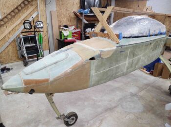
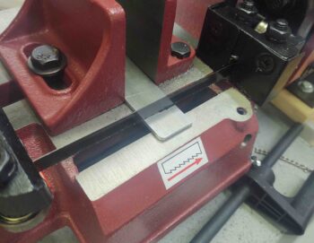
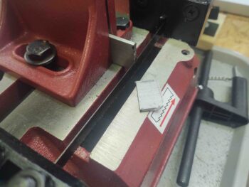
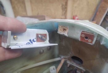
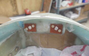
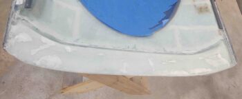
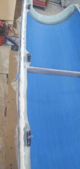
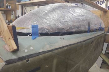
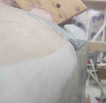
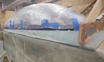
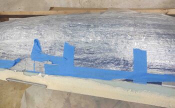
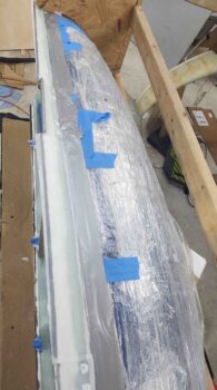
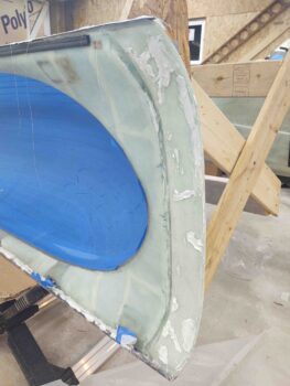
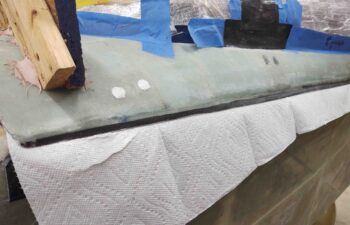
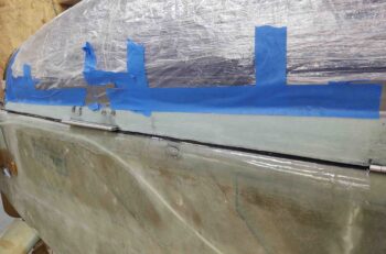
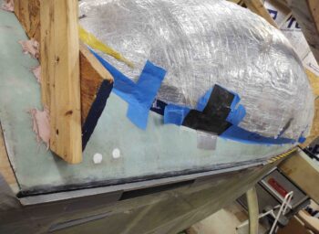
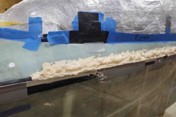
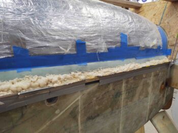
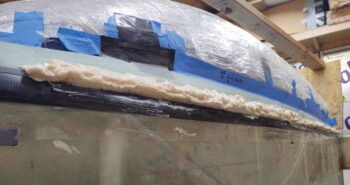
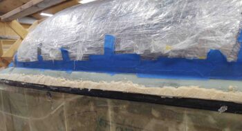
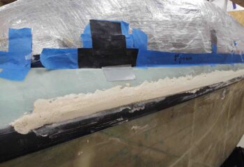
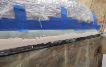
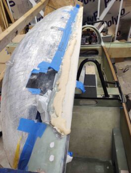
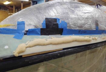
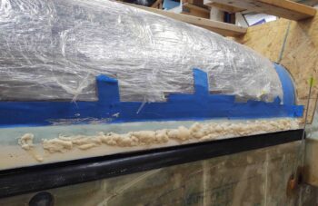
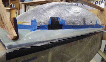
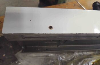
Today I started off by marking the edges of the glassed-over block of H250 foam I buried in the front of the nose, right at the top aft side of the furthest forward bulkhead.  I placed this block of uber dense foam here to mount the nose hatch door hinge bracket assembly to, although I never had a concrete plan as to exactly how that would look…. until now.

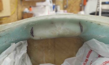
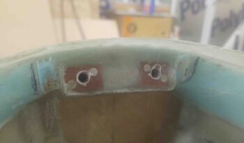
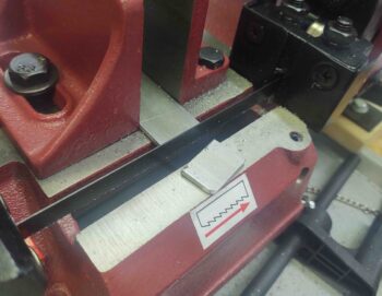
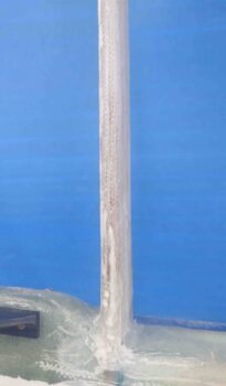
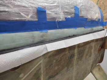
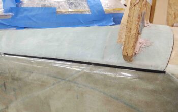
I then used my Fein saw and trimmed about a 1/4″ wide channel –going forward– at each mark.

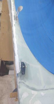
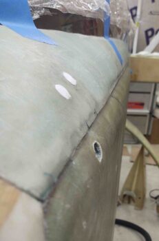
These slots are where the hinge pins will protrude out each side, left and right, of the hinge bracket assembly.  Then the hinges will mount inside the slots on each side of the bracket.

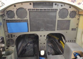
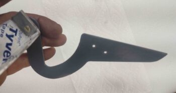
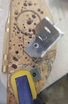
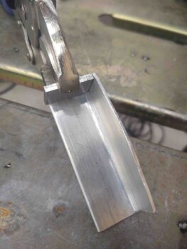
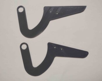
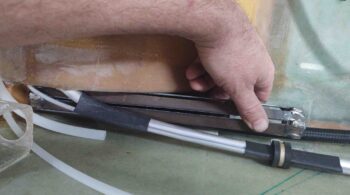
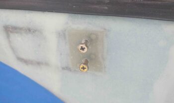
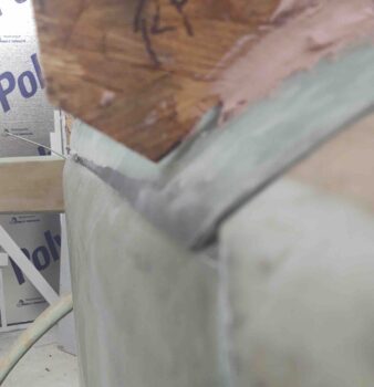
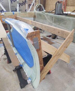
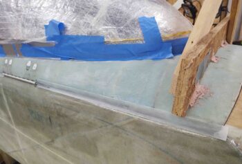
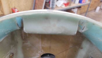
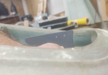
I tested the original hinge configuration and grabbed a shot of it here.  As you can see, if I raised up the top mounting edge of the hinge (the front edge is elevated enough to touch the hatch door already) to be parallel with the door line, it would literally protrude through the top of the door.

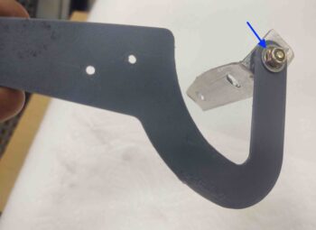
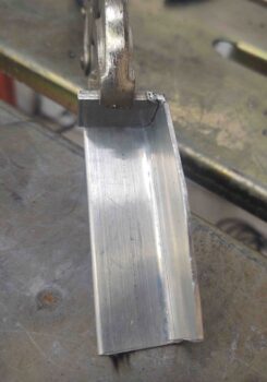
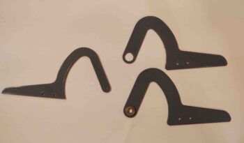
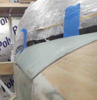
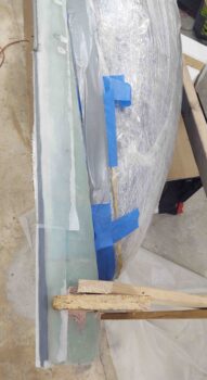
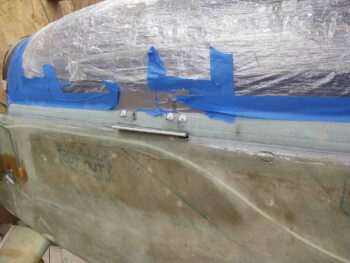
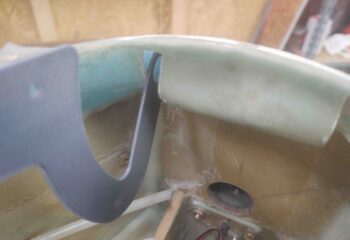
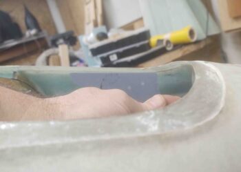
Here we have the new modified hinge with the pivot point in nearly the exact same spot as above, but as you can see the top portion of the hinge that will mount to the door is about parallel with the line of the door…. much better!

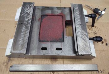
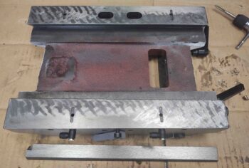
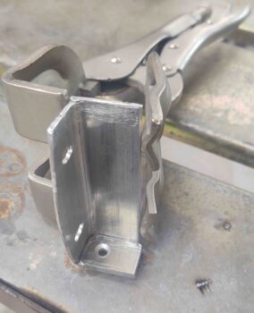
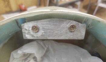
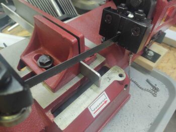
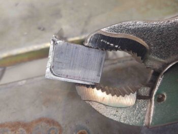
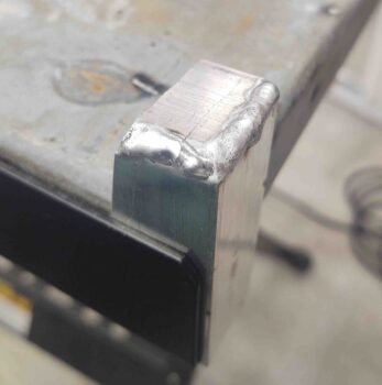
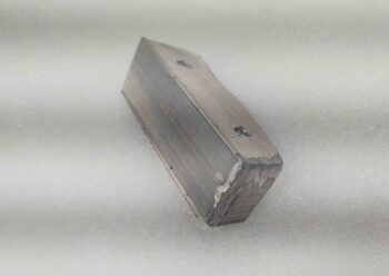
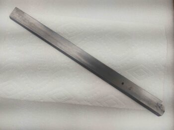
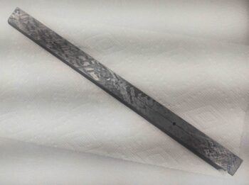
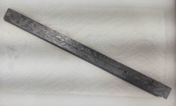
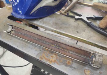
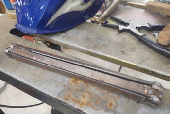
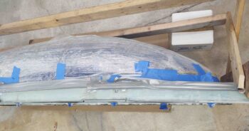
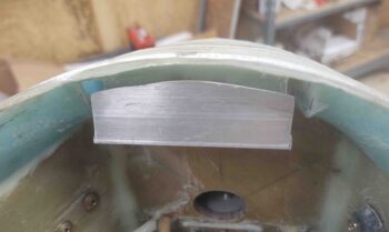
I then trimmed the 1/16″ thick by 1″ x 1″ angled aluminum to serve as the main body for the bracket.  My band saw isn’t the most robust so it got a little wavy on the left top edge, but since this will buried under the nose I’ll just file it down a bit and call it good…. function over perfection!

I will note the ends will be capped each with a piece of 1/8″ aluminum that I’ll weld into place.  Sticking out of each end will be a 1/4″ long x nearly a 1/4″ in diameter nub that will serve as pivot points (ala “axels”) for the hinges.  The hinges will be secured to these nubs either by E-clips or cotter pins.

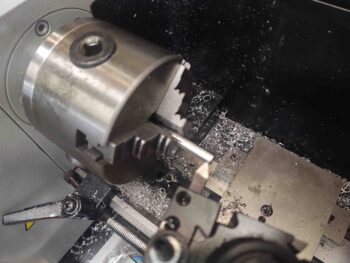
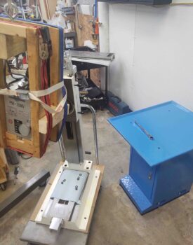
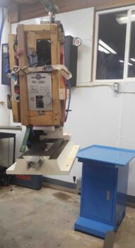
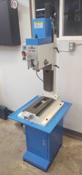
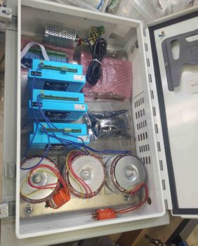
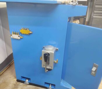
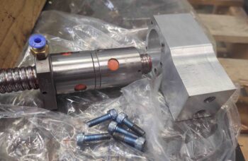
I’ll warn you now, the rest of this blog post is all about reassembling the milling machine. I started off with mounting the One-shot oil reservoir and 2 each 4-port manifolds.  These will feed oil, via plastic tubing, to 8 oil ports on the milling machine.

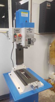
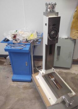
I then got busy reassembling the milling machine.  I mounted the column back on top of the base.

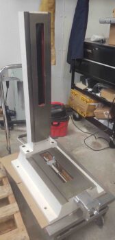
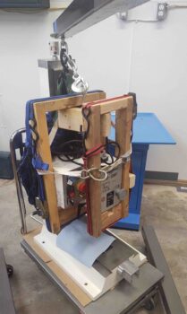
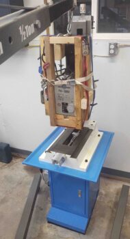
I then turned the mill column and base assembly on its side.

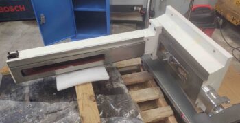
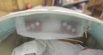
Why?  To mount the air spring back into place at the very bottom of the base, protruding all the way up into the column.

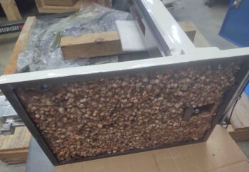
A wider angle shot of the bottom of the mill base, with the epoxy granite in place.

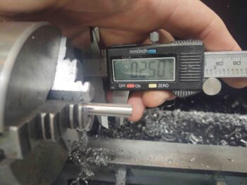
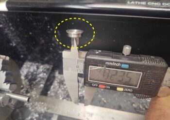
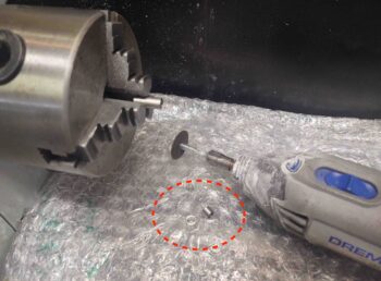
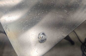
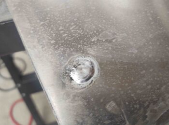
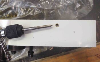
I then got to work drilling out the ball oilers to convert them to tubing push-adapters.

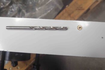
I first drilled it out with a #19 drill to tap M5 threads (too big IMO, so I reduced it to #21 and worked much better).

I then tapped the remaining brass of the oiler with M5 threads.

There were a couple of things that happened next that distracted me from getting a close-in shot of the tubing push-to-fit adapters I was mounting in the converted ball oilers, but you can see a shot of one on each side of the Z-slide (column) in the last 2 pics.

First, I wanted to replace the standard grease fitting on the Z-axis ball nut because there is no physical way that I can get to it when the Z-axis ball screw is mounted in the column.  I had some tubing push-to-fit adapters that are actually for 3D printers, but a guy I follow on YouTube (Franco) converted his PM-25 milling machine to have full-time remote greasing capability of the ball screws using these fittings.

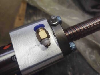
So I mounted one here (to be clear, I’ll be using oil on the X and Y axis ball screws because they are more prone to getting chips and debris thrown their way, whereas the Z-axis ball screw is hidden away in the column).

After trying a few times to bend space and time with my mind to get the Z-axis ball screw down into the column, I realized I was going to have to remove the Z-axis ball nut-to-Z-slide bracket (R, pic below) to then mount the bracket first, followed by the Z-axis ball nut (and attached ball screw/motor mount).

I’ll take a moment to remind anybody reading this that I do not have any instructions on how to do this…

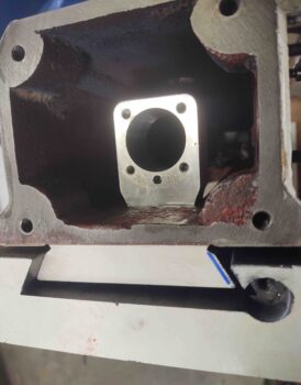
I then installed the Z-axis ball nut-to-Z-slide bracket.  Here you can see the 2 big 10mm hex head screws (top) that attach the Z-slide to the bracket.

And a peak down into the column to see the bracket attached in the center of the column.

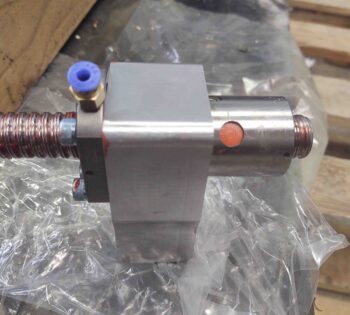
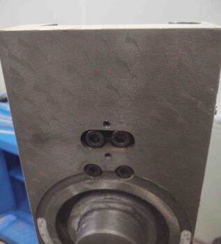
I then attached the Z-axis ball nut, ball screw and stepper motor mount to the Z-axis ball nut-to-Z-slide bracket.

Then threaded in and tightened all 5 bolts.

If you look closely you’ll see the original grease fitting back in place.  Why?  Mainly as a dust cover really… since the space is too tight to use the tubing adapter I had to punt on that idea.  So in the future I’ll simply be putting the tip of my oil can through the opening on the right and using oil to lubricate the Z-axis ball screw.  Oh well . . . live and learn!

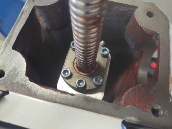
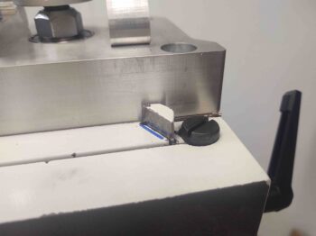
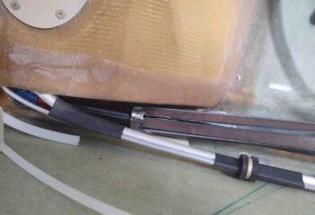
Just another shot of the Z-slide (left) and the Z-axis ball nut (blue bolts securing) and the Z-axis ball screw (covered in red aircraft grade grease).  Note the oil line adapter threaded into the tapped old ball oiler (center bottom).

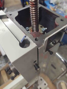
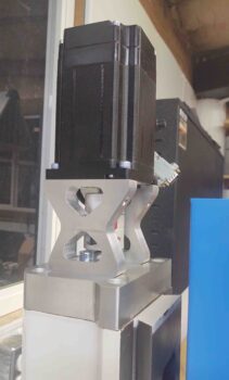
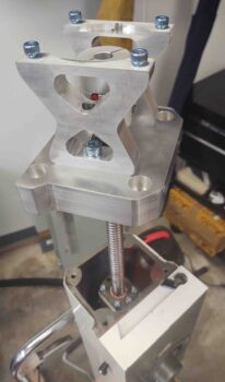
I then seated and bolted the motor mount to the top of the column with 4 large bolts (Again, note oil line adapter on side of Z-slide).

Tomorrow I plan on getting a whole lot more done on the nose, and perhaps a bit more on the mill as well.


Chapter 13/22 – Tweaking hinges

Today was more of a planning day vs. a work day.

I did get a few hours of work in on the milling machine CNC control box backplate for mounting components (power supplies, motor controllers, etc.) into it.

I also assessed the hinges and hinge assembly on the front nose hatch.  After doing some mental and cardboard mockups on the hinges’ configuration, I determined that the aft tip (right end below) needed to be around 20ºish degrees/1″ higher to interface with the hatch door interior surface at the appropriate angle.

The upper hinge is the one I tweaked the aft attach portion angle.  You can tell the difference by focusing on the 2 small holes: parallel with edge on previous version, and at an angle on latest mod.

In addition to getting the hinge tweaked in Fusion 360 CAD and 3D printed, I also updated the instrument panel CAD drawing to its latest edition.  Should be very close to being ready to go final on that SOON.

I plan to focus on the nose and some on finishing the canopy once I get the Scratch-Off canopy cleaner from VANs (to remove build scratches & blemishes).  In addition, I will be putting a decent bit of time in on getting the milling machine up and running.


Chapter 13/22 – One ugly wrench!

I started off spending a good bit of time cleaning and tidying up the shop today.

I then got to work on a task that has been on the To-Do list for a long, long time: torquing the 1/2″ oil heat line fittings to the 1/2″-to-3/8″ reducers that run to/from the oil heat exchanger.

Since these oil line fittings sit right adjacent to the GIB fuel sump/thigh support they are quite a bit more inaccessible than I had planned on when I mounted them in that location. I was never able to fully confirm that they were appropriately torqued, so I needed a way to tighten them up to specs.

Moreover, this is a task I really needed to get accomplished pre-strake build since it would be even more of a near-impossible task to do with the strakes on.

I essentially took a Harbor Freight hollow hex “wrench” that comes in a set for plumbing, cut about 5/8″ off one end (left end, pics below), and then cut away 2 of the wrench flats to give me a 4-sided “C” piece left over.

In part of my straight line cut tests for the plasma cutter, I cut a 1″ x 1/16″ strip in half lengthways, to give me 4 x 12″ x 1/2″ strips.  I then MIG welded these strips to 4 of the flats of a 3/4″ bolt on one end (right end, pics above/below), and the “4-side C” I made above on the other (left) end.

This gave me both the clearance of the hose to get in & around the oil hose fitting hex nut, while also giving me enough length to reach down along side of the thigh support to get to the oil line fitting.

What it didn’t give me was enough torque to tighten the oil line fitting as much as it should be… it was just too springy and hard to gauge.

So I went with Option #2 –which is actually better in the long run– which this ugly wrench allowed me to do: simply remove the oil line fittings from the reducers.  I’ll then mount the 1/2″ oil lines to the reducers first, then mount the reducers into the thigh support/fuel sump front face bulkhead (a bit of trimming will be required).

Either way, getting this taken care of pre-strake is big on my list, and I’m glad this ugly wrench was able to work in facilitating it.

My next task was to start on the nose… specifically the nose hatch hinge assembly.  I’ve played around with different configurations on how to mount it, and one really viable option now is to mount some flanged bearings into the hinges to then mount into the nose.  The current hinge (on the left, below) was set up to simply use a 3/16″ bolt through it, but that configuration has some clearance issues.

The bearings cleared up the clearance issues, and in the long run is the simpler solution, so I widened the hinges to nearly an inch wide to allow for a bigger diameter hole to seat the bearing into.

It actually took me a little bit to tweak this in Fusion 360. I had just kicked off the 3D print of the new hinges, was making sure the first few layers went down well, and then was getting ready to head back out to the shop to start working the bracket side of the nose hatch hinges when my little buddy called me.  She’s been having a bit of a hard time at school so I took a few-hour break to go hang out with her.

When I returned home, my newly designed hinges were done on the 3D printer bed.  To be clear, I’m not crazy about the fatter design, but they will be stronger overall and can of course take the 1/2″ OD bearings.  Also, I’ll note that these are test hinges, subject to changes, and the final ones will be aluminum.

Tomorrow I plan on getting back on the nose and really digging into those tasks to get it finished.

Chapter 18/22 – Tech: Back in Black

This post is pretty much all videos . . .

The biggest news of the day is that I finally got my plasma cutter operational again.  It took a fair bit of machinations to make it happen, but it is cutting at a very acceptable level now.

So much so that after the initial test cut was successful, I dove right into cutting test instrument panel #2.  Here’s the video of the panel being cut.

With the new test panel on hand, I then finished an ongoing series of videos that originally covered both the panel and the canopy latch handle, but the resulting video would have been way too long to stuff into one video, so I broke them up.

Here’s the video on the instrument panel, including the one I just plasma cut:

The canopy latch handle progression really comes down to this one critical part at its core: the triangular interconnecting piece.  I snapped this shot to show just a few of the iterations it’s already gone through in just a couple of weeks.

And finally, here’s a video recounting the evolution of my canopy latch handle.

And after a long night of video editing, I’ll bid you adieu!

Chapter 18 – Good as it gets: part 2

I started off today spending about 45 minutes sanding the micro I applied to spots on the front canopy lip.

I had embedded some nutplates under the interior canopy skin, so I also drilled those out to make them functional.

I then got to work on the line of flocro that I placed under the left edge of the canopy to straighten out and help fill in the gaps of my “B” canopy seal.  It was still a bit rough when I finished, and I need to do some more work on it as I dial in the “B” seal fitting.

With my extra micro from the layup last night, I also filled in the holes and divots on the canopy cross brace piece… especially both ends where it meets the canopy frame.  I then sanded them today.

After all my tasks were done on the canopy, I remounted it on the fuselage.  Here’s the left side after I redid the edge.

And a look down the line. Much, much better than before.  Not perfect, but a heck of a lot better!

Left side BEFORE:

And the reworked right side as well.

And another close-up view down the line.  Again, a LOT better than before.

Right side BEFORE:

I also reinstalled the canopy latch system & handle and messed around with that for a little bit.  It gave me enough data to tweak the CAD file for the triangular interconnect piece and then reprint another one.

Chapter 18 – Edge Saga Over!

Today I had to run some important errands, so I didn’t get into the shop until the evening.

I started by trimming up the right side edge glass that I laid up on the canopy yesterday.  I got it so that the canopy could open and close with plenty of clearance between the longeron/fuselage and the added glass.  I then removed the canopy.

Since I was working on the side of the canopy I went ahead and set it on the shop floor.  I then sanded and prepped the side for some pour foam.  At the front and aft end you can see some dams for the foam.

I then poured a couple of rounds of foam.

I hit the cured foam first with a hacksaw blade to knock off the major stuff, then moved into sanding it to shape.

With the canopy so low on the ground, I could already feel it in my back from bending over so much… definitely wasn’t going to make it through a multi-hour layup.  So I turned my workbenches on their side and put the canopy on them… perfect height!

I then spent another few hours total on the canopy right side edge/frame layup.

Again, like the left side I took nearly 0.2″ of foam off the edge and filled it with carbon fiber UNI, then laid up 1 ply of BID over that and the added foam.

I had a decent bit of epoxy left over after I peel plied the layup, so I mixed up some micro and applied it to the rough spots on the underside of the front canopy lip.  This was on my task list for the canopy anyway, so now I have a head start on it.

And with that, I called it a night.


Chapter 18 – Gettin’ edgy!

I started off today by trimming the canopy left side lip extension, and since I have black duct tape on the longeron for protection, I threw some white paper towels underneath for contrast (note: black = carbon fiber).

I then prepped the right side for glass.  Now, I did cheat just a hair on the left side and went out 1/2″ (vs. 3/8″), but on the right side I have the front hinge constraining how far out I can go (note: here black = duct tape).

I then glassed the canopy right side lip.  I had a bit of epoxy left over, so I whipped up some dry micro and filled the hinge screw counterbores.

I took a close up of the left side to show an issue I’m contending with: when I glassed the canopy I had an indention that ran down the aft 3/4 of the canopy lip.  It didn’t really effect extending the lip out, but it will need to be accounted for in the final shape of the canopy left side frame.

After assessing how much material needed to be added to shape the canopy left side frame, I decided to move forward with pour foam to fill & reshape it.

I added a mini-shelf with a couple pieces of angled aluminum.

I then very sloppily added the pour form.  I didn’t need it to be perfect here, just workable.

After the pour foam cured, I removed the mini-shelf.

And then did a quick major foam removal with a hack saw blade.

I then did round one of shaping with a sanding block.

I decided I needed some more filling foam at the top edge of the foam I had just put on… but didn’t want to mess around with a bunch of forms, etc.  So I opened the canopy and set the frame on a box to get the best angle possible for a “level” pour. I did make up one quick tape dam at the very front just to ensure it didn’t go running down the front of my canopy.

I then whipped up another batch and poured it out.

Here’s the canopy left-side pour foam application round 2.

I then did a quick hack saw blade removal and sanding just like round 1.  Here we have the canopy left side pour foam shaped and ready for glass.

And here, 3 hours later, is the new canopy left side frame.  Note the bottom edge of carbon fiber UNI (for strength and to add to the thickness of the flange).  I then added 1 ply of BID to cover the carbon fiber edge and the pour foam side.

That’s pretty much it for the left side.  I’ll of course pull the peel ply and trim the edge, but tomorrow will be all about working the canopy right side lip and getting it dialed in as close to the left as possible.