
With my new welder, and in over 7 years total!
I have company coming in for the weekend and need to do a lot of tidying up since I’ve been in hermit mode for the last 6 months, and plane build mode for 2 of those… combine that with my unfinished house projects and it’s quite a clutter. Over 3 hours total on that side project.
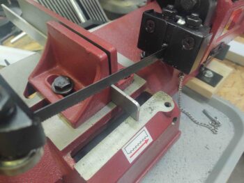
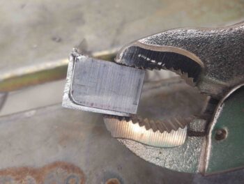
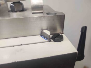
Out in the shop I started by measuring and then using my horizontal bandsaw to cut a piece off a 1/8″ thick x 1″ bar of 6061 aluminum for an end piece on the nose hatch hinge bracket.
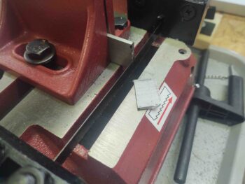
I then cleaned it up and using a big pair of vice grips, clamped it onto the right side of the 1/16″ thick 6061 aluminum angle that will serve as the main nose hatch hinge bracket.
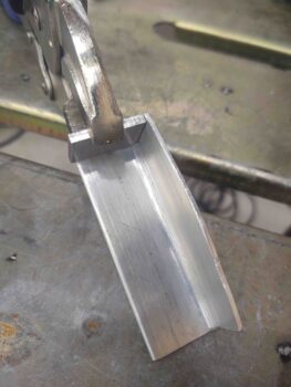
After spending a good half hour re-learning what all the myriad of knobs do on the front of my new TIG welder that I’ve had for almost 6 months, I then got around to testing it out for the first time by hitting the bracket with a quick tack weld in the corner.
I then reset my vice grip clamp . . .
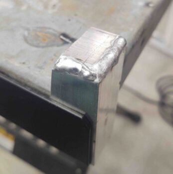
And welded ‘er up. Not great, but not horrible for not having done AC/aluminum welding in over 7 years. In fact, last time I welded aluminum was at the EAA TIG welding course I took in Georgia in early 2013 while deployed to Tampa, FL.
A note that since I don’t have my bench grinder set up yet for sharpening TIG tungsten electrodes, I grabbed a sharpened one that was much bigger than the 1/16″ called for to do this job. That would in part account for the copious amount of filler material on the weld (but more so my rustiness!).
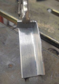
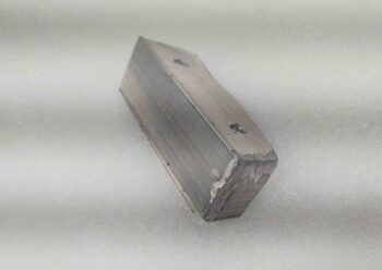
I then ground off the extra aluminum left on the welds. I’ll clean it up much nicer later. With the end plate welded in it allowed to me set the bracket and then press it to the left and know my left-right placement to drill the pilot holes for the screws and the upcoming embedded nutplates.
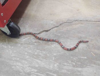
During this process I had a curious snake visit the shop. I’ve never seen this coloring before –just stunning– and as best I could tell he’s a Scarlett King snake. He was literally just passing through as he came from the front of the shop and went out a small hole at the base of the air compressor closet and was gone.
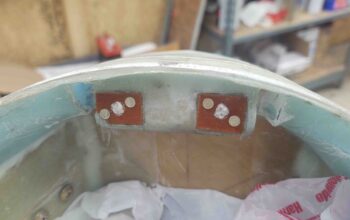
To ensure alignment between the bolt holes I drilled in the bracket and the nutplate assemblies I made up, I had originally planned to mount the nutplates onto the bracket and then clamp the bracket into place with nutplates secured to it. But I couldn’t see behind the bracket and I could not tell 100% what was going on. I didn’t want a nutplate on one side embedded as it should be and the other side off –but floxed– securing it into the WRONG place!
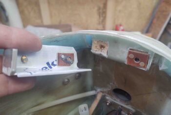
So I decided to simply flox the individual nutplate assemblies into place and then adjust the hinge bracket mounting holes slightly if required.
Just a side note since I saw it and I don’t think I posted a pic, but this is when I had some left over epoxy from the canopy right frame lip layup . . . I had whipped up some micro to put on the canopy crossbar and front lip, and also used some to fill in the gap around the small piece of upper fuselage I had removed to check the integrity of my embedded roll bar securing nutplates. So I’ve pretty much put that puzzle piece back into place and reset to zero… 6 weeks later!

Back on the milling machine for a bit:
I had plasma cut the milling machine’s CNC control box back plate out of 0.090″ 6061 aluminum, the same stuff I’m using for the instrument panel so I can dial in cutting amperage and speeds on this non-critical part to get the best cut on the panel. In addition, I’ll also be using this aluminum plate for the front nose hatch hinges.
Well, the 4 corner mounting studs in the CNC control box are actually NOT square to each other, so the right side holes came out fine while the left were off. As Marco discovered in creating his last instrument panel version, a good trick to have in your pocket is the ability to fill in a hole on the panel and then recut if you need to move or reposition an item on your panel.
I thought I’d try this out with my mill CNC control box backplate, again a non-critical item. I conferred (ahem… “BS’d”) with Marco a bit on the phone just to make sure I wasn’t missing anything on what is technically called a ‘rosette weld.’
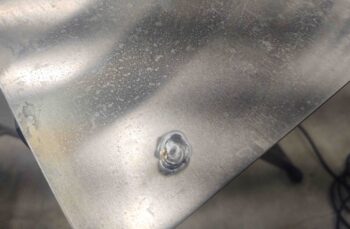
The welds took about 10 seconds each and came out fine for my purposes here. Literally just swirling the torch around while dabbing in a bunch of filler metal.
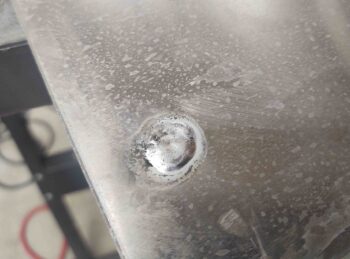
After cleaning up the excess filler metal, I then used the plasma cutting table to re-cut these last 2 holes…. and after re-checking a half-dozen times before pulling the trigger I’ll be darned if they still weren’t off a bit. At that point I simply called no joy and widened the holes a bit with a drill and got it installed.
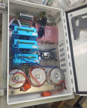
Here’s a shot of my mainly checking if all the mill CNC components will fit both in the control box and on the backplate. One of the holes I just filled, recut and then finished drilling by hand is in the lower left corner. The other, not really visible, is in the upper left corner.
I then got busy on the actual mill. It was getting a bit late, but I at least wanted to get one significant thing done on the mill, so I marked and then drilled a through hole (lower right) on the Z-axis gib.
From there I drew out my lines on the face of the gib that interfaces with the angled slide portion of the Z-axis column.
And proceeded to Dremel out approximately 1mm deep oil channel distribution lines. This mod allows oil pumped in from the One-shot oiler to come through the hole in gib to then spread somewhat evenly between the gib and angled Z-axis rail for much better lubrication.
I then mounted the gib back into place on the right side of the Z-slide.
And called it a night.