
My first task in the shop today was to get a 2-ply BID layup over the nose hatch hinge bracket nutplate assemblies that I embedded with flox yesterday. I then peel plied the layup.
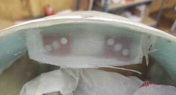
As the layup cured, I got to work on a hollow stainless steel shaft that I ordered from McMaster-Carr and was just delivered mid-morning. I’ll be using the shaft as a sleeve over the screw/bolt coming out of each side of the nose hatch hinge bracket, and for the flanged ball bearing press fitted into each hinge to ride on.
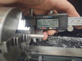
The sleeve OD is right at a 1/4″ (0.250″) . . .
While the ID of the bearing is 6mm, or around 0.235″.
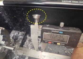
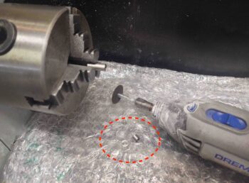
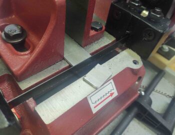
I then used the lathe to take down the SS sleeve OD to just under that of the bearing ID.
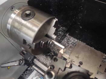
My parting tools suck, especially on stainless steel, so I just marked the cut line and then used the Dremel as I had the sleeve rotating in the lathe chuck.
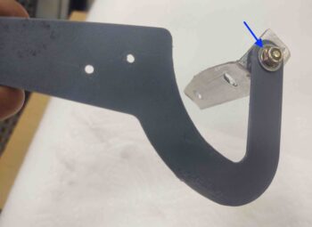
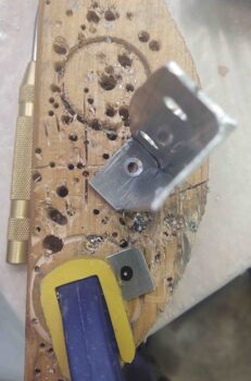
Since the last 3D printed test hinge was right in my sight, I grabbed it to test out the bracket-screw-washer-bearing/hinge-nut setup. Once together, it all worked nicely.
Note the flange of the press-fit bearing (blue arrow).
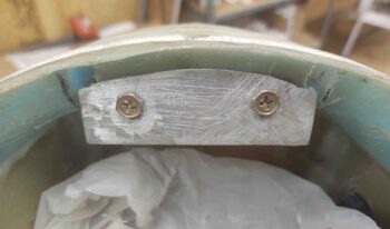
Here’s a shot from the inside of the bracket, with the countersunk #8 screw head showing.
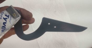
I then cut the 1/8″ x 1″ 6061 bar stock for the other (left) end of the nose hatch hinge bracket.
I then marked the screw hole to match the right side of the hinge bracket (although I forgot to countersink the hole, which is one reason I drilled the hole prior to welding… argh!!).
I then prepped the hinge bracket for welding.
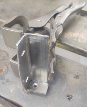
A bit later, after a horrendous welding session, I test mounted the bracket. The inside corners were just being really tough to get any good welds into, totally exacerbated by my lack of practice or any recent TIG work. I simply put too much heat into this aluminum part and actually cracked it as I was trying to bend the slightly heat deformed right side back to vertical.
I then realized that this bracket just became the prototype for proof of concept of my hinge install setup, and that a new thicker (and taller) bracket would need to be constructed (or possibly milled …. hmmmm?).
After loading all my pics I also realized I didn’t get a shot of the finished layup …
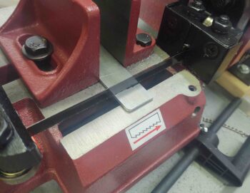
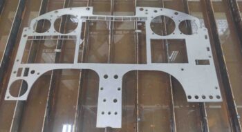
On the bright side, I did get a good cut on the plasma cutting table of test instrument panel #3. I really do believe this will be the last test panel I cut (although I still need to test fit and assess).
Besides some more shaving off of the upper left corner, the biggest change on this panel version is that I moved the ELT remote control head from just above the row of circuit breakers in the lower right corner, up about 6″ to sit adjacent to the Mini-X EFIS.
[Interesting tidbit: There are 4 small pieces that were cut out from the panel that are “welded” to the tops of the slats . . . can you find them?]
Now for some exciting mill news!
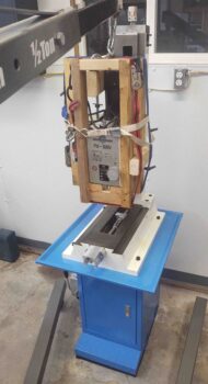
I got my hoist all set up and rigged up the mill headstock to get it into position to mount onto the 3 big bolts protruding from the column-mounted Z-slide.
After getting the headstock re-mounted onto the mill, I then grabbed a thick sling and rigged the mill to be hoisted onto the blue base.
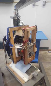
Here we are, mid-hoisting . . .
I then slowly lowered the mill onto the blue base and bolted it into place.
The initial front-to-back (Y-axis) . . .
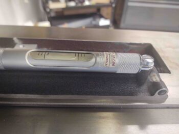
And left-to-right (X-axis) leveling looked near perfect… until I tried the Y-axis on the right side. It was off a bit, so that made the entire leveling outcome a big compromise to get all sides within specs…. which are my specs, btw.
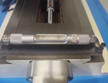
After an hour of shimming all around, I got the mill base (not the blue pedestal) dialed in so that the level bubble was within the big solid lines. All had a scant more gap on one side of the bubble than the other. But remember, this level is SUPER sensitive, and about the thickness of sheet of paper (or less) will move the bubble back into exact center. Unfortunately, one low corner knocks the whole leveling endeavor into a wonky compromise.
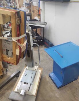
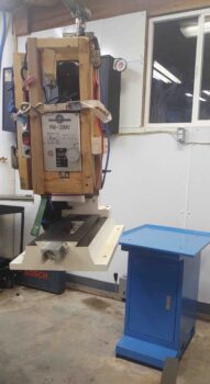
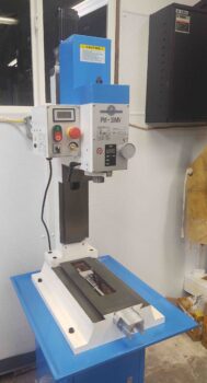
With that, here’s the mill in its current state.
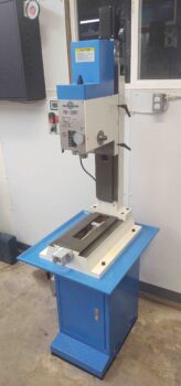
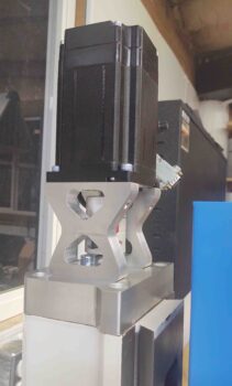
Another shot. Note that I also mounted the Z-axis stepper motor on top of the column.
A closer shot of the installed Z-axis stepper motor.
Both the nose hatch door hinges and the mill are slowly coming along…. Of course I hope to have both operational very soon!