Here are a couple shots of the battery strap in place.
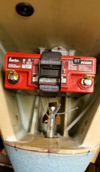
It works as designed, keeping the battery in place nice and secure!
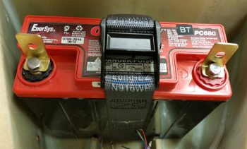

Here are a couple shots of the battery strap in place.
It works as designed, keeping the battery in place nice and secure!
Today I received my custom battery straps to secure the main battery in the battery compartment. The strap and buckle are military grade that will easily hold a 15-pound battery in place.
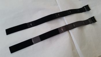
Since the main cost was for prototyping up the first strap, I went ahead and ordered a second one in black.
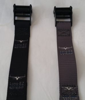
I got these from Strapworks out of Oregon, and for the most part I’m pleased with them. I will say however that I think they could have done a little better job with the placement of the images, which for some reason seemed to be quite the challenge for them. Oh well, a minor issue in the grand scheme of things!
Today was quite the beautiful day here in Northern Virginia, so after messing around with my school work for a couple of hours, getting my motorcycle battery charged up enough to get it started and out for a quick scoot, and then spending just over an hour on the phone with my building nemesis Marco (ha!)…. I finally got into the shop!
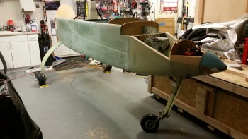
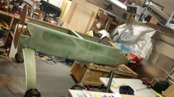
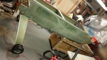
My main goal for this afternoon was to get the fuselage off the dolly and into its grazing stance, which I did as you can see below. Before I actually offloaded the fuselage from the fuselage dolly, I did a bit of Spring cleaning in the shop and attached the rollbar and headrest to the fuselage.
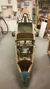
My next task was to install the battery in the nose and connect up the wiring leads to get the nose gear to extend and finally get this bird on all 3 wheels!
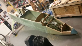
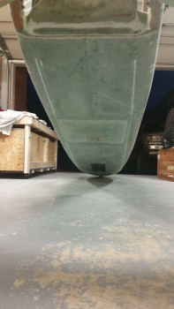
First, I wanted to get a couple of shots of my grazing fuselage from the aft end.
Especially this shot, where the nose is fully resting on the nose bumper, which of course is the aerodynamically clean shaped nose bumper that my buddy Marco CNC’d out of a hockey puck. He did a fantastic job on it!
I then got the battery installed into the nose battery compartment and the power cables clamped into place. Note in the pic below you can see the nose gear backup battery immediately aft of the main battery.
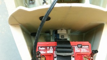
I shot a video that covers the majority of work I’ve completed over the last few months. Then, at the end of the video, I raise the nose by extending the nose gear for the first time during this build. Note that I merely strapped in the battery, attached the leads, and then shot the video. There was no previous testing to ensure it worked and the initial nose raising in the video is just that, the initial nose raising in real time. I’m just glad it worked! Whew!
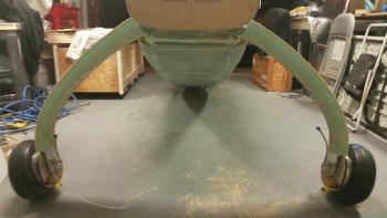
I took one final pic of the fuselage on all 3 wheels before closing up shop for the evening. This of course is another huge milestone for this build!
Over the next few days I’ll be doing a final check on the wheels to ensure the toe-in is correct and set for one final time! In addition, I’ll also be prepping for installing the wheel pants.
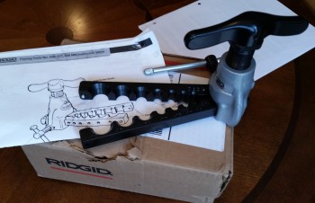
First off, UPS delivered my Ridgid 37° flaring tool yesterday morning. This tool will enable me to flare my 3/16″ stainless steel brake tubing, thus allowing the final pieces to placed into the brake line system. Now, this tool’s specs does not specifically state that it’s rated for stainless steel, but many of the reviewers on Amazon did clearly state that they used it with very good results on stainless steel. So I figured I would give it a try. I will tell you that it is much bigger than it looks in the pics, and this thing is a heavy, robust beast.
Secondly, I’ve been doing a fair amount of research on my toe-in dilemma and I’ve decided to pull the wheels, configure the fuselage upright without the fuselage dolly in the way and do one final toe-in setting to get them to specs. After reviewing both the plans, what other canardians have done, and even the standard on other types of aircraft, I’m concerned my toe-in is too much, even for a heavier than plans bird. I would probably not mess around with it if it were, say, 0.5″ total vs. the 0.45″ total called out for in the plans, but I’m significantly over at 0.6+”.
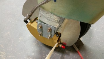
Finally, I’ve been updating my to-do task list and one thing I forgot to add came up today when I took a couple of pics to send to Marco earlier. I was pointing out how the aft tab of my right heat shield was just barely kissing the brake caliper… as I’m pointing to in the pics below. I’ll trim about 0.1″ off that area when I remove the wheels (AGAIN!) to set the final toe-in.
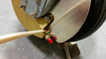
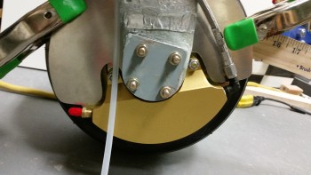
As you can see, the left side heat shield clearance is fine.
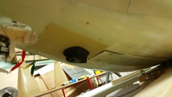
This morning I got an order from McMaster-Carr with my 1-1/2″ stainless steel cap head screws to replace the 1″ screws Marco had included with the nose bumper. Since I had to install the nose “Exoskeleton” over the 1/4″ thick 2024 aluminum skid plate that has K1000-4 nutplates riveted to the back side of it . . . well, clearly I needed longer bolts. This makes today the first time that my nose bumper has been officially mounted on the lower nose!
As for the build, I’ve clearly not been in the shop much lately. This is due primarily to my Commercial Pilot Rating ground school which, to be honest, is kicking my butt as far as the amount of time required to complete the course work. I’m trying to get ahead of the power curve, but then I fear once I start flying, the pace will only worsen. We shall see. I do honestly believe that once I can stop playing catch up and get into a good battle rhythm, that more work will get done on the plane build.
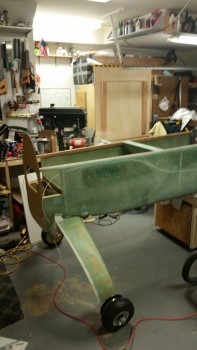
Tonight was a milestone in that it was the first time the fuselage has rested on the main wheels … ever!
I lowered the fuselage dolly platform to get the fuselage as low as possible to slide it aft on the fuselage dolly and thus get the main gear wheels on the floor.
Forgive the camera angles, but I was backed up all the way in the corner and trying to get as wide angle of a shot as I could!
After I got the fuselage set so I could access the CL on the belly, I started attaching straight edges, running strings and plumb bobs, etc. to double check the toe-in on each side. As I suspected, I jacked up the toe-in pretty good after I had set them correctly from the first go around with the gear in the air.
When I flipped the fuselage over I had double-checked the toe-in and it seemed to be either negative (wheels pointing out) or not enough. So when I mounted the wheels I sanded down the mounting pads to reset the toe-ins correctly. Of course, as often is the case, I should have left well enough alone!
With access to the CL mark on the belly this evening, I could actually determine the CL to double check my toe-in measurements. After it was all said & done this evening, I confirmed that my left wheel assembly is mounted approximately .08″ farther outboard than my right, which is not enough for me to worry about any further.
However, my toe-in is much more than it technically should be with each side a hair over 0.3″. I figure that per plans the max you want to be at is 0.45″ combined, and I’m sitting just under 0.65″ combined. However, since my plane will have a bigger engine and weigh a couple hundred pounds more than what Burt was originally planning these birds to weigh in at, I’m not going to make something not-so-great even worse by mucking about with it. At least not right now. I’ll wait until I do my high speed taxi tests to see how my tire wear is progressing & then adjust fire from there.
Tomorrow I’ll get the fuselage dolly out from under the front of the fuselage, lower the nose gear and play around with that a bit and grab some pics for prosperity sake. I’ll then start working on prepping the wheel pants for install.