Chapter 22/23 – Threaded EGT bungs

I got a little bit done in the shop today as I’m getting ready to head out of town for Christmas and New Years.  I’ll be gone over a week.

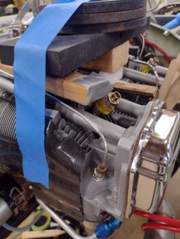
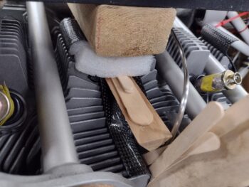
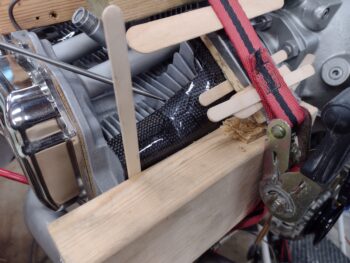
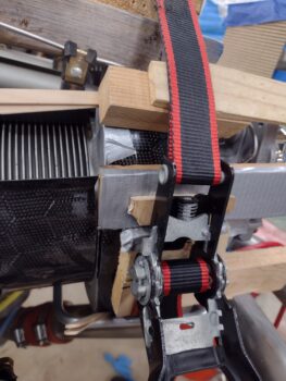
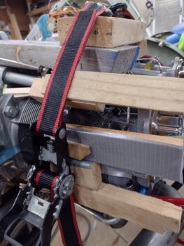
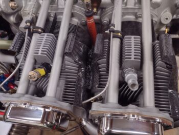
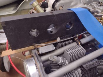
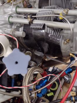
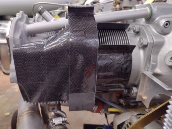
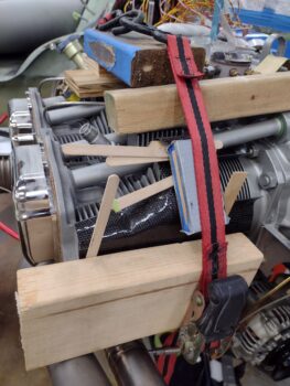
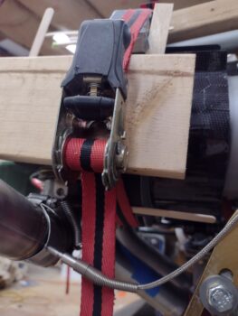
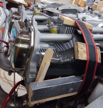
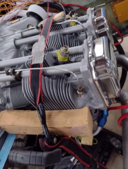
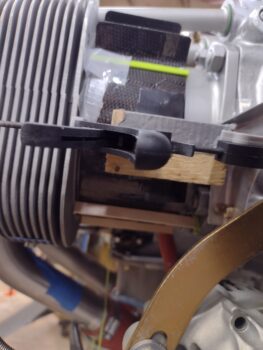
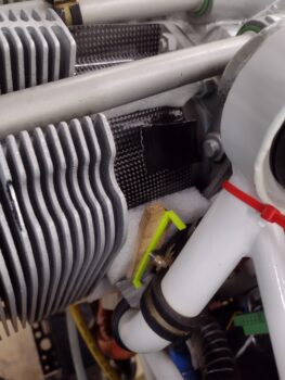
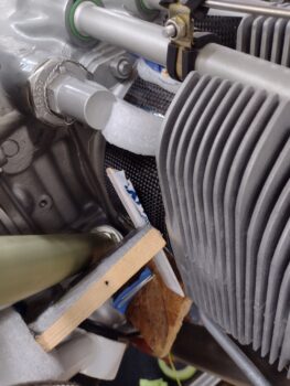
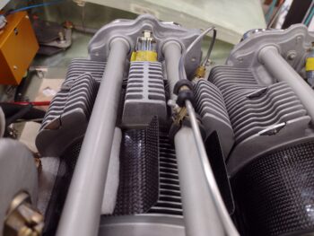
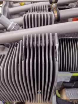
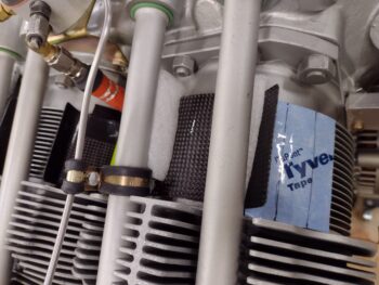
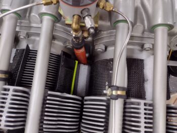
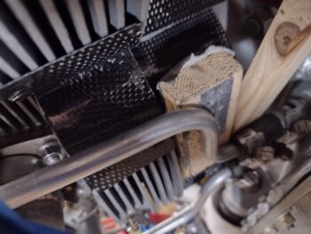
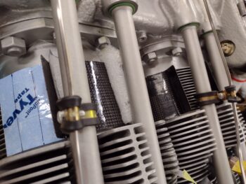
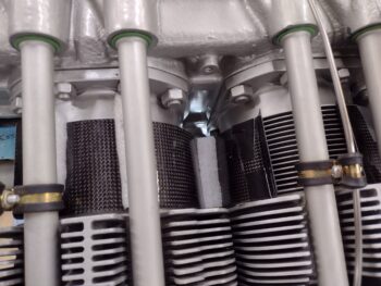
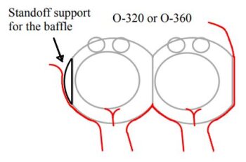
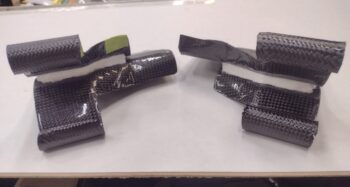
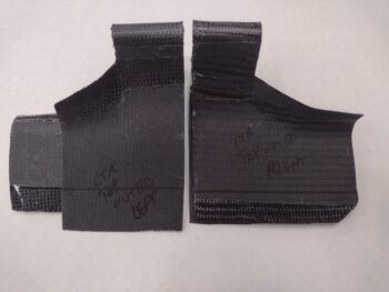
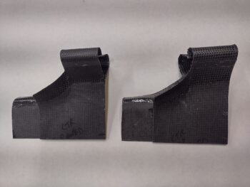
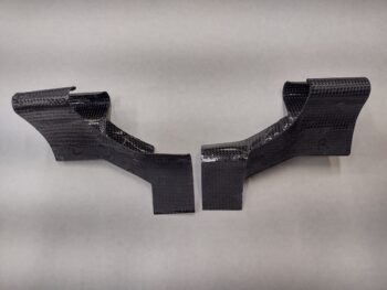
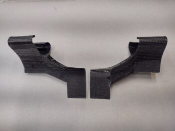
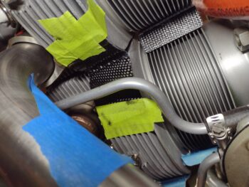
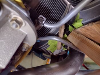
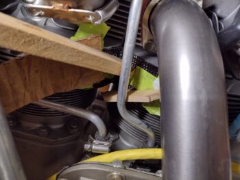
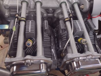
I started off by removing the weights, wood and wedges off of the right top outboard inter-cylinder baffles.  That all came out pretty good.

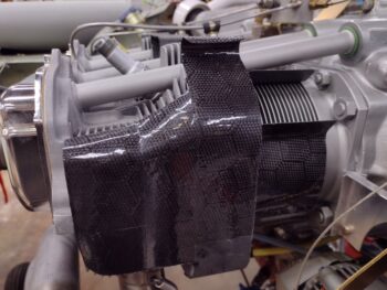
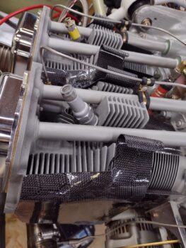
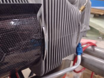
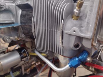
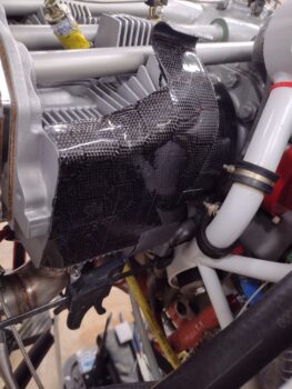
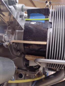
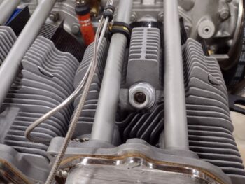
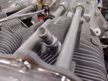
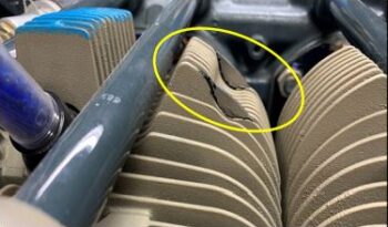
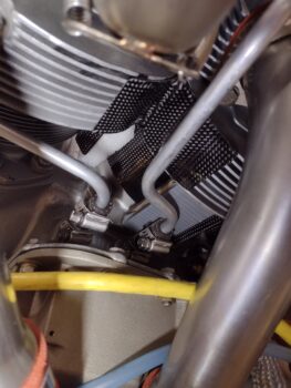
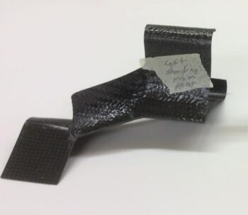
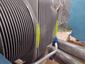
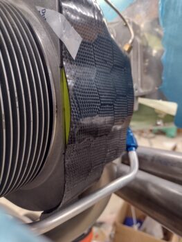
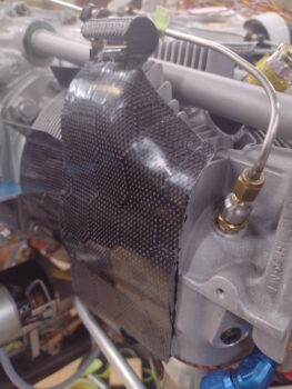
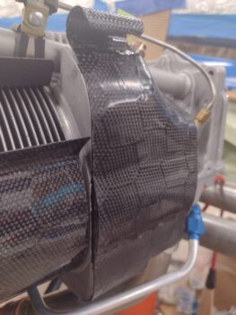
I also grabbed some unhindered shots of the aft right baffle on cylinder #2… also not too bad!

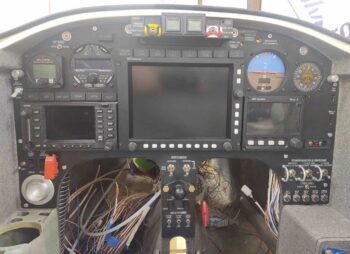
In my “spare” time (usually later at night just before I hit the bed) I’ve been assessing my MGL clock in the upper left instrument panel corner as well as the Trutrak ADI, just to the right of the center EFIS.  Mind you I’m not looking at changing anything before first flight other than knowing what requirements may lie ahead in doing any instrument swaps.  I will want to modernize the TruTrak ADI spot to something that could give me a backup AI/PFD and an HSI tied directly to the GNS-480.

I discussed the uAvionix AV-30 a while back, which would be perfect… if it worked! Unfortunately it appears to need some major re-engineering to get some bugs out.  Especially if it is to be used as an IFR backup instrument.

The Garmin GI 275 looks promising as well —albeit expensive!— but comes in 3 different major flavors, the cheapest being the CDI/MFD combo that would tie in very well to the GNS-480 and provide a back-up CDI, but not an HSI.  Nor a PFD/AI.

After doing some hunting around on ACS and online, my first serious query was visiting my RV-driving cousins to see what they were up to in the world of back-up instruments… and found this little gem.  Apparently there is an engineer over in Slovakia that has made a whole line of some impressive avionics, a company called Kanardia (isn’t that fitting!).  This is their HORIS PFD.

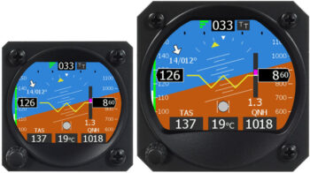
Since I want a clock in the upper left corner of my panel (obviously since I have the MGL clock there currently) I could have the chrono function screen displaying as the standard screen and then flip over to the PFD/AI if I needed to bring that online as a backup.

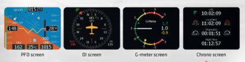
Here we have the different function screens of the Kanardia HORIS PFD:

Again, I’m just spit-balling some ideas and brainstorming here, and honestly spending about as much time writing this up in this blog post as I did puttering about online finding out this info.  My initial thought is that if I do happen to go the Garmin GI 275 route, then I would still want a capable AI displaying somewhere on my panel.  It’s all about optimization and squeezing every drop of functionality into the small amount of panel space we are afforded in these Long-EZs.

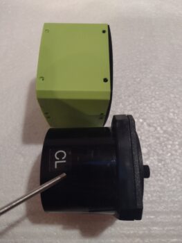
On the Kanardia website they had 3D models of their stuff, so I simply downloaded the file for the 57mm (2-1/4″) HORIS PFD and spent a few minutes to kick off a 3D print (then headed out to the shop).  It took 2 rounds of 3D printing to have the basic outer shell of the HORIS PFD.  Here it is in comparison to the current MGL clock:

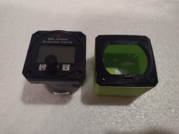
Note the MGL clock is made to either be mounted behind the instrument panel plate or on the front surface of the panel, as I have it configured on mine.  Moreover, note the HORIS PFD does note have the cylindrical body and is essentially a cube.

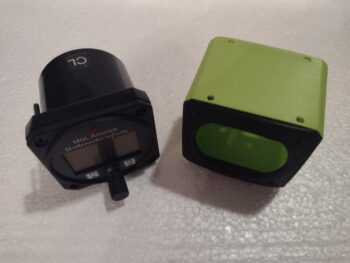
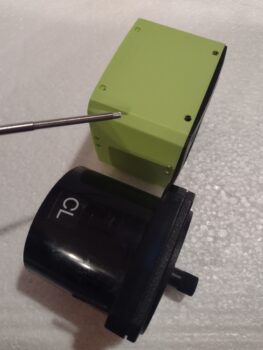
Another comparison shot of the HORIS PFD (top) vs the MGL clock.

The HORIS is a couple of millimeters wider and taller than the MGL clock, and doesn’t have quite as big of a chamfer on the corners (note my pointer in the pic).  One reason I surface mounted the MGL clock on the panel is due to the tight clearance on the front side of the panel with the slope of the nose.  Thus, my concern for ANY future swap out of this 2-1/4″ instrument is the internal/front side panel clearance at this position. Clearly better to remedy this now with NO avionics currently in the panel rather than later on down the road with a fully populated panel.

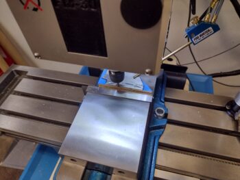
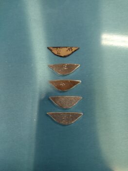
In other news, I received the stainless steel M8-1.0 threaded bungs for the compression fitting EGT probes.  These new bungs are much beefier than the 1/8-NPT I had picked up from McMaster-Carr, and weigh a good 1/2 ounce more… very noticeable when holding them in your hand.

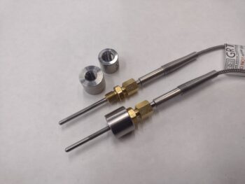
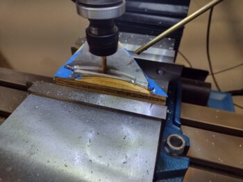
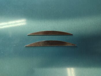
Not only are the new threaded EGT bungs wider in diameter, but they’re a tad taller too.  I plan to throw them on the lathe for some mandatory weight reduction!

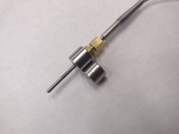
Clearly the good news side of all this is that the EGT probe compression fitting threads mate up fine with these new bungs!

I’ll be heading off on my holiday adventures tomorrow morning, so I’ll be back with more build shenanigans and reports in about 10 days.

Merry Christmas and Happy New Year everyone!

Chapter 23 – Right mid baffle in place

Today I pulled all the dunnage and securing strap off the aft right baffle on cylinder #2… and of course didn’t think about grabbing a pic of that until after I had already taped up the weights (to ensure they didn’t topple over) that are securing the glued-in top outboard inter-cylinder baffles in place on the right side.

As par usual with these inner CF baffles, I had to engage in a bunch of crazy shenanigans to get the baffle completely set in place and secured during cure.

I also removed the securing strap, dunnage and wedges from the left baffle that I re-glued onto the aft side of cylinder #1.

Here we have a shot of all the currently installed left side CF inner baffles.  Now I just have the inboard cross-shaped baffle segments to install on each side, with an angle tab that will go in to help keep those secure in the face of the oncoming air.

And with that, I set up my requisite heat lamp underneath the engine and left the just-glued right side inter-cylinder baffle to cure overnight.

Chapter 23 – Baffle fin standoff supports

I headed out to the shop today to specifically get the cylinder #2 fin standoff supports made.

But as I was looking over the already installed CF inner cylinder baffles, I noticed some gaps on the aft left cylinder #1 baffle.  It just wasn’t fitting right.  I pulled the baffle off, cleaned up the glue and then went through a series of test fits.  I found the culprit being the first 2 outboard fins (note the pointer in the pic).  I trimmed about 1/16″ (0.060″) off the rounded corners of these fins and also angled them down on the outboard edge of each fin.  I also aggressively sanded the inside of the baffle at the mating area with these fins.

It’s hard to tell in this pic of course, but the baffle fit is MUCH better and sits significantly tighter on the cylinder.

With my unplanned and impromptu baffle redo out of the way, I then finally got around to machining the inboard fin standoff support for cylinder #2… out of some scrap 0.090″ thick 6061.

With the inboard standoff support (the larger of the two) complete, I then set up and milled the outboard standoff support.

Here we have the cylinder #2 outboard (top) and inboard (bottom) fin standoff supports ready for attaching to the aft cylinder wall.

And here are the cylinder #2 fin standoff supports glued in place.

I had to run into town to grab a few things at the store and stop by Jess’s place for a couple of items as well.  After a few hours time to let the standoff support glue setup I then glued the right aft baffle in place over and around the standoff supports.

Today’s tasks knocks out all the major front and aft CF inner baffle installs.  Tomorrow I plan on getting the right side top inter-cylinder baffle (the “Star Trek Enterprise baffles”) glued into place.  Then it will just be the top inboard inter-cylinder baffle pieces that need to be trimmed and set into place.

Trust me, if you’re tired of reading about these baffles… I’m tired of installing these darn things.  I want them DONE!

Pushing forward.

Chapter 23 – Left major baffles in

Well, yet another day and more goals NOT reached!

I had planned on getting the cylinder #2 standoff supports machined/cut out and glued on today, but too many holiday social planning and prep events filled my day.

I was able to remove the tape, weight and wedges off of the left top outboard inter-cylinder baffle, which is the completion of all the major inner CF baffle pieces on the left side of the engine.  I do still have an inter-cylinder piece (plus bracket) that needs to go in between the base baffles to fill that void (right around the orange fuel line).

Again, the weather has been pretty darn cold here as well, so that isn’t helping things.  I will try to get out to the shop tomorrow and get the cylinder #2 standoff supports made and glued in place…. but the way things have been playing out this holiday season, I ain’t promising anything!

Inching forward…

Chapter 23 – Left mid baffle in place

I’ve been doing a bunch of holiday prep since I’ll be heading out of town to spend Christmas with my daughter, son-in-law and grandkids.

My goal for the build today was to get the left side top outboard inter-cylinder baffle glued into place —including the crazy machinations in securing it in place during its cure!— and then move onto machining the right side cylinder #2 aft standoff supports and get those glued into place to allow me to then get the actual aft baffle attached tomorrow (after the 18 hour cure cycle).

Well, I did get the left side top outboard inter-cylinder baffle glued and secured into place.

Then, before I jumped into machining the cylinder #2 standoff supports, I cleaned up all the inner baffle forms, carefully packed them back up in the box they were sent to me in, and then ran downtown to send them back.  Clearly the chapter of this build involving these CF inner baffles is ever so slowly coming to a close.

Even a bit slower after the events that ensued upon my return to the shop.

I worked out the CAM post processing for the cylinder #2 aft standoff supports and prepped some 0.090″ 6061 to machine for the creation of the standoffs.  Not having used the milling machine in a few months, it required a good 45 minutes of TLC in cleaning and oiling before I got started.  I also forgot a couple of weeks ago I had a pressure line inside my compressor closet burst, which needs to be repaired… so I had rig up another compressor to handle those duties (my milling machine quick tool changer, chip removal mister and air blaster are all on one of these lines).

Once ready to go, I learned that my handy hack of using super glue and blue tape has its limits: a thicker material such as 0.090″ with a smaller footprint just can’t hold up against the pressure of the end mill biting into the corner as it cuts… I tried this method twice with no joy.

At this point in the evening is was late and after multiple iterations and all the required prep, I figured I will have to do some more Neanderthal machining by cutting these things out with my Dremel Tool.   Jess was due over in about an hour to make us a nice dinner, so I decided to kick this can down the road until tomorrow since I would most likely only get one of the two standoff supports manually cut out and shaped (I still have a thought on machining standoff #2 which I’ll attempt tomorrow).  Only gluing one of the two standoff supports into place clearly wouldn’t put me any more ahead with the cure cycles required.  So I called it a night…

Chapter 23 – Baffle install update

I had yet another very busy day in prep for my upcoming holiday adventures, again getting nearly nothing done in the shop.

I did carefully remove all the wood supports and straps that secured cylinder #1 and #4 baffles in place during glue cure.

First off though, here is a pic of the elusive frontside baffle on cylinder #3.  I finally remembered to grab a shot!

And here we have the baffle now secured to the aft side of cylinder #1.

Finally, here is the baffle for the front side of the cylinder #4.

That’s all I have to report for today.  I do plan on machining the standoff supports for the aft-side baffle on cylinder #2 ASAP to get that mounted.  Then it will back to the top center area on each side of the engine to get the inter-cylinder baffle pieces installed.

Chapter 23 – Outboard baffles install

I’ve been a bit busy prepping for Christmas and New Years as I’m heading out of town to my daughter’s for Christmas and then on to Nashville and the mountains of Tennessee to ring in the New Year with Jess.

Yes, between my non-build shenanigans and the cure time for the Toyota FPIG glue on the baffles, it’s taking a number of iterations to get these baffles on.  The current cold weather doesn’t help and the crazy machinations required to pin each individual baffle to its respective cylinder for cure is also somewhat of a gargantuan feat each round.

Case in point: Note the insane amount of dunnage required to both the secure the aft left baffle to cylinder #1 while at the same time ensuring that nothing on the engine gets damaged either.

Here’s a low-angle shot of the baffle (that is pretty much hidden from view from all the wood blocking) going onto the aft side of cylinder #1.

In the same manner, here is the baffle for the front side of cylinder #4 glued and secured in place.

And this is how that looks from the aft side of the engine.

I just simply didn’t have time to machine the cylinder #2 standoff supports yet, but will get to it my next major outing in the shop.  As par usual, after I grabbed these shots I set up a heat lamp under each side of the engine pointing up and then covered the top of the engine to keep the heat in during the baffle glue cure.

In addition, I did actually get the baffle installed on the front side of cylinder #3 last night.  I thought I had a pic of that but didn’t and consequently completely forgot about it in yesterday’s blog writeup.  I’ll get a pic of it for tomorrow’s post.

Pressing forward… slowly!

Chapter 23 – Base baffles installed

Today I got all the remaining outside cylinder (fore & aft) base baffles glued onto the engine cylinders.  I thought I would show one of the baffles here with the Toyota glue applied just before it went onto the cylinder.

Here we have the 4 final cylinder base baffles glued and secured in place, starting clockwise from top left: Aft left/cylinder #1, aft right/cylinder #2, front left/cylinder #3, and front right/cylinder #4.

You can see I employed everything but the kitchen sink to secure these base baffles in place during cure, each cylinder/baffle combo clearly being completely unique as compared to the other ones.  It took about 45 minutes per baffle to prep, create and dry run the securing accoutrements.

In addition, the Toyota glue needs 15-18 hours to set up for final cure, so I left them to cure and pressed on with some Neanderthal machining.

I made up templates (one shown below) for the different sized inboard and outboard fin dip filler tabs since the inboard is a bit bigger than the outboard.  I tried to put these into F360 CAD but it was being finicky (or I was) so I punted and just went ol’ skool using the bandsaw and the Dremel with a cutoff wheel to get them cut out.

I didn’t grab a shot of the 4 outboard fin dip filler tabs before I glued them into place on the respective cylinders, the left shown here.

I used 0.050″ thick aluminum on the outboard because the fin at this point is the same thickness as all the other fins, around 0.080″.  The final inboard fin on the cylinder head is the thickest of all the fins, nearly 1/8″ thick.  Because I had some scrap that fit the bill in not having to cut into any fresh stock, I used 0.090″ thick aluminum on these inboard fin dip filler tabs.  Here they’re shown with the template I made up.  The marks are again from my Neanderthal machining where I had to use vice grips to hold the tabs while shaping them… these inboard tabs especially are not cosmetic, so I’m not overly concerned about these “tooling marks.”

On a few fins, both inboard and outboard, I had to account for paint buildup globs and actually create a divot in the mating edge of the filler tab to allow it to fit flush with remaining dip surface edge.

Here we have both inboard and outboard fin dip filler tabs glued in place (Toyota FPIG) on the left cylinders (pic 1) and on the right cylinders (pic 2).

This shot shows the thicknesses of the inboard vs outboard fin dip filler tabs.

Finally, I’ll remind everyone that these filler tabs are my blatant copying of Dave Adams’ same efforts that he wrote-up in a COBA Canard Aviation article.

Tonight was again a very cold night, with frost already forming late in the evening.  I put heat lamps under the engine pointing upwards and covered the top of the engine just to ensure there was decent temps for the glue to cure.  Tomorrow I plan on installing more baffle segments while also machining the 2 each cylinder #2 fin/baffle standoff supports.  At this pace it will be at least another 2 days before all the inner baffles are installed.

Chapter 23 – Base inner baffles

I had to do a bunch of running around today so didn’t get into the shop until mid-evening.  My goal was to get at least 4 baffle segments installed and I’m happy to report I accomplished that… in my effort of doing so it felt the same to me as a video I saw where a kid juggled Rubik’s cubes while solving them.

First, I removed all the aluminum outer front and side baffle walls to ensure I could get the placement down on the front cylinders’ base baffles.

To get the 3x glue swaths in the correct spots and then get these internal baffles set into place was definitely quite the puzzle, unique on each one.  On the aft side of the forward cylinder I actually applied the glue to the cylinder fins and only actually applied the glue to the baffle at the center.  That baffle went on first.

On the forward side of the aft cylinder I applied the glue to the center and top, then slowly and careful wove the baffle in under the push-rod tubes before setting the top and middle in place.  Both Mike Beasley and Steve Beert said they used wood wedges and tape to wrangle the baffles and keep them in place during cure.  Me being me, I went a slightly different route and found that the dense foam that comes in shipping boxes worked a treat for securing the baffles in place.

Once I got the aft inside baffle top and center secured in place, I got underneath the engine and used a pick to pull down the bottom edge of the baffle just enough to use a stir stick to apply the bottom swath of glue.  After the bottom swath of glue was applied, by pushing the center larger piece of foam all the way down in between the cylinders, it served to press the bottom aft baffle edge up against the cylinder for cure.

On the underside, for the forward baffle on the aft side of the front cylinder, I employed the cylinder oil return lines to secure wood blocks and some foam strips to add just enough pressure to keep the baffle in place.  Note the installed outboard inter-cylinder baffle that I glued in place last night.

I then did the same thing on the right side.

Now, let’s discuss baffle angles and airflow through these base baffles.  As you may have noted the forward and aft base baffle sets do NOT have the same air entry and exit angles: for a couple of different reasons (Also, let me point out here that I am focusing on FUNCTION over FORM and am looking to optimize airflow for cooling… not the goal of having standardized looking baffles).

First, the air coming off the ramps are significantly different in the angle at which they come into the cowling via the armpit air scoop.  The air hitting the inlet ramps for the front cylinders turn almost directly upwards —or at least at a much sharper angle— as compared to the more shallow angle the air on the aft ramps is directed.  This obviously means direct air flow needs to be more vertical, or slightly angled aft, on the front cylinders vs the aft cylinders (clearly there is a HUGE pressure component to how our engines are cooled, but I’m not getting into that here).

Next is a matter of simple space… or more specifically clearance.  Even if my goal was to make the front and aft base baffle entry and exit points the same, the oil return lines under the cylinders would require major trimming of the bottom flange on the forward baffle.  There’s just very little space on the bottom side of the forward cylinders.  That being said, I will need to create a half-moon notch on the bottom tab of the aft right side base baffle (not installed at this time) to account for the cylinder #2 oil return line.

Here’s an underside shot of the right inter-cylinder base baffles glued and secured in place.  Again, note the tape and wood shims removed from the bottom outboard inter-cylinder baffle (I discussed in yesterday’s post how the form for these outboard baffles is not perfectly true, which makes them set a little wonky when in place).

The pictures don’t do the amount of effort in planning, dry runs and execution justice to get these 4 inter-cylinder base baffles glued in place.  All in all I spent nearly 4 hours on getting these baffles alone glued into place and secured for cure.  Tomorrow I plan on knocking out another good chunk of the inner CF baffle installs as well.

Chapter 23 – Starship Enterprise Baffles

Today was all about finishing the trimming, shaping and creation of the top outboard inter-cylinder baffles that I micro’d together last night.

I did a good bit of research today to ensure I knew what the heck I was doing because I wasn’t completely understanding the configuration of these specific baffles, even though Steve Beert sent me another conformational pic.  What was confusing me was why was there no baffle coverage on the fins in between the 2 cylinders?

I went back to Andreas Christou’s document, Design for optimal cooling efficiency, and therein lied the answer!  Things are a bit different from our smaller cousin, the O-235, than they are for O-320/360s… read on:

The Lycoming O-235-L2C Cylinder head… has less fin depth at the sides, and some attempt has been made to increase cooling on the exhaust valve side of the cylinder. The fin depth next to the exhaust valve is slightly more than on the intake valve side. There is enough fin depth to justify using Bid/RTV baffle material between the cylinders so that the flow of cooling air is divided into two sets of fin tubes. This will distribute more cooling air to the exhaust valve side and will also keep hotter air from the exhaust side from heating up the intake side and consequently raising the temperature of the incoming fuel air charge.

[Note the red line in between the cylinders denoting a baffle]

Andreas then went on to state this about the O-320/360 motors:

Placing Bid/RTV baffle material between the fins of the cylinder heads would do more harm than good. Any inter-cylinder baffle material would block the flow of air past the intake side of the cylinder.

[Note there is NO red line in between the cylinders denoting a baffle]

Eureka!

This would also explain why my buddy Marco found issues on his O-320 Long-EZ because when Terry Lamp built it everyone else was installing O-235s.  The baffling in that Long-EZ’s O-320 was per the O-235 IIL plans and caused some significant heat issues. I’m not calling Terry out nor being critical of him… that is an outstanding bird, and the poor guy had only the guidance for the O-235 to follow at the time!

With the above foundational info in hand, I then got to work on what Steve Beert calls the “Starship Enterprise” baffles.  First, here’s a shot of the separate baffle segments micro’d together to make one baffle piece per side.

I then marked the bottom edge of the top inter-cylinder baffles for trimming…

And then trimmed them up.

After another round of confirming the shape and configuration of these baffles, I then trimmed them up even more to their final shape on the lower side.  Here’s Side A:

And here’s side B.  I also final trimmed the top sides as well including the curly Q’s.

I had thought about and even mentioned spray painting the micro black with hi-temp spray paint, but then just decided to use the Toyota glue to add just a hair more depth, fill some gaps around the edges and of course cover up the white micro.  In addition, this allowed me to use the Toyota glue (RTV? Whatever it is!) and get a feel for how it could be applied and manipulated.  It’s not the sexiest looking stuff here, but it’s done, and remember: these are on an engine!

With my mastery of the Toyota glue complete (haha!) I decided to knock out some low hanging fruit: attaching the bottom outboard inter-cylinder baffles.  I figured these are pretty low-vis baffles and if I really got messy with the glue while slapping these things into place then they wouldn’t be very noticeable, eh?

I started on the left side and applied the Toyota glue in 2 strips across each face of the somewhat Λ shaped baffle and then taped it in place.  I will note that when I cut the baffle on the imprinted edge that the form created, it came out about 0.030″ narrow on each side.  Each edge is still on the respective outside fin, just not fully all the way around… it’s just a tiny hair off kilter so each side was a task of getting the best coverage possible with a slightly askew and every-so slightly narrow baffle.

On the right side the tape wasn’t holding at all… and it was quite the melee getting it on and set in place.  As you can see I used wood and cardboard to wedge it into place.  Here’s a shot from the inboard looking out…

And a shot from outboard looking in.  I can definitely say I’m glad that this small but crazy baffle is in place!

In other news: I forgot about these 3D printed standoff supports which I actually printed out yesterday and just got around to taping them in place on the aft side of cylinder #2.

I then test fit the cylinder #2 aft baffle in place.  Both standoff supports need some very minor tweaking, with the inboard standoff (shown) needing a bit more added to the depth while the outboard standoff needs just the opposite.

And with that I double checked the bottom outboard inter-cylinder baffles and called it a night.