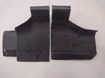
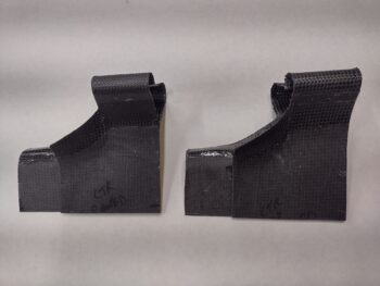
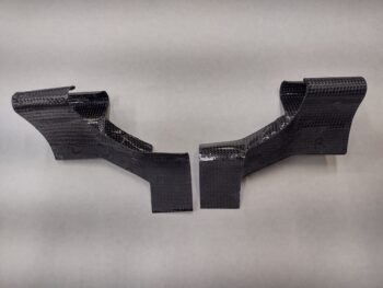
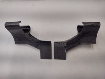
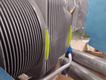
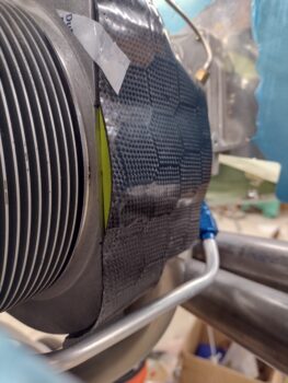
Today was all about finishing the trimming, shaping and creation of the top outboard inter-cylinder baffles that I micro’d together last night.
I did a good bit of research today to ensure I knew what the heck I was doing because I wasn’t completely understanding the configuration of these specific baffles, even though Steve Beert sent me another conformational pic. What was confusing me was why was there no baffle coverage on the fins in between the 2 cylinders?
I went back to Andreas Christou’s document, Design for optimal cooling efficiency, and therein lied the answer! Things are a bit different from our smaller cousin, the O-235, than they are for O-320/360s… read on:
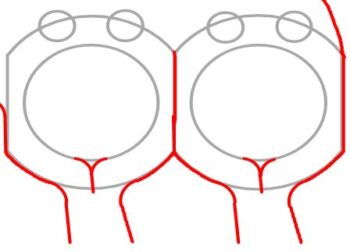
“The Lycoming O-235-L2C Cylinder head… has less fin depth at the sides, and some attempt has been made to increase cooling on the exhaust valve side of the cylinder. The fin depth next to the exhaust valve is slightly more than on the intake valve side. There is enough fin depth to justify using Bid/RTV baffle material between the cylinders so that the flow of cooling air is divided into two sets of fin tubes. This will distribute more cooling air to the exhaust valve side and will also keep hotter air from the exhaust side from heating up the intake side and consequently raising the temperature of the incoming fuel air charge.”
[Note the red line in between the cylinders denoting a baffle]
Andreas then went on to state this about the O-320/360 motors:
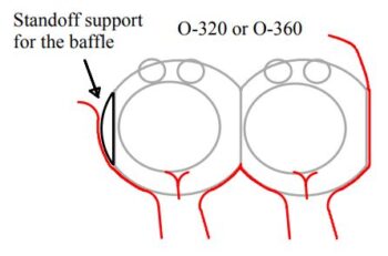
“Placing Bid/RTV baffle material between the fins of the cylinder heads would do more harm than good. Any inter-cylinder baffle material would block the flow of air past the intake side of the cylinder.”
[Note there is NO red line in between the cylinders denoting a baffle]
Eureka!
This would also explain why my buddy Marco found issues on his O-320 Long-EZ because when Terry Lamp built it everyone else was installing O-235s. The baffling in that Long-EZ’s O-320 was per the O-235 IIL plans and caused some significant heat issues. I’m not calling Terry out nor being critical of him… that is an outstanding bird, and the poor guy had only the guidance for the O-235 to follow at the time!
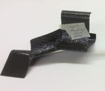
With the above foundational info in hand, I then got to work on what Steve Beert calls the “Starship Enterprise” baffles. First, here’s a shot of the separate baffle segments micro’d together to make one baffle piece per side.
I then marked the bottom edge of the top inter-cylinder baffles for trimming…
And then trimmed them up.
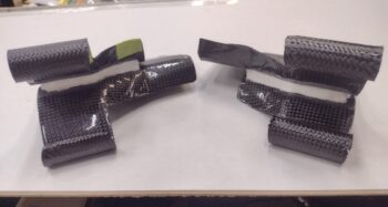
After another round of confirming the shape and configuration of these baffles, I then trimmed them up even more to their final shape on the lower side. Here’s Side A:
And here’s side B. I also final trimmed the top sides as well including the curly Q’s.
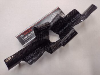
I had thought about and even mentioned spray painting the micro black with hi-temp spray paint, but then just decided to use the Toyota glue to add just a hair more depth, fill some gaps around the edges and of course cover up the white micro. In addition, this allowed me to use the Toyota glue (RTV? Whatever it is!) and get a feel for how it could be applied and manipulated. It’s not the sexiest looking stuff here, but it’s done, and remember: these are on an engine!
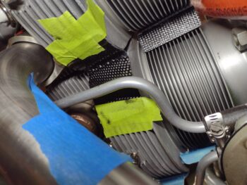
With my mastery of the Toyota glue complete (haha!) I decided to knock out some low hanging fruit: attaching the bottom outboard inter-cylinder baffles. I figured these are pretty low-vis baffles and if I really got messy with the glue while slapping these things into place then they wouldn’t be very noticeable, eh?
I started on the left side and applied the Toyota glue in 2 strips across each face of the somewhat Λ shaped baffle and then taped it in place. I will note that when I cut the baffle on the imprinted edge that the form created, it came out about 0.030″ narrow on each side. Each edge is still on the respective outside fin, just not fully all the way around… it’s just a tiny hair off kilter so each side was a task of getting the best coverage possible with a slightly askew and every-so slightly narrow baffle.
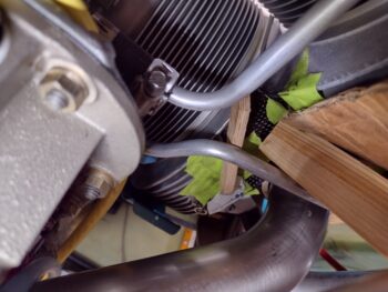
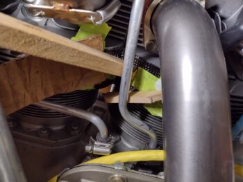
On the right side the tape wasn’t holding at all… and it was quite the melee getting it on and set in place. As you can see I used wood and cardboard to wedge it into place. Here’s a shot from the inboard looking out…
And a shot from outboard looking in. I can definitely say I’m glad that this small but crazy baffle is in place!
In other news: I forgot about these 3D printed standoff supports which I actually printed out yesterday and just got around to taping them in place on the aft side of cylinder #2.
I then test fit the cylinder #2 aft baffle in place. Both standoff supports need some very minor tweaking, with the inboard standoff (shown) needing a bit more added to the depth while the outboard standoff needs just the opposite.
And with that I double checked the bottom outboard inter-cylinder baffles and called it a night.

