Chapter 23 – Top inter-cylinder baffles

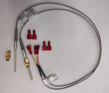
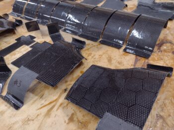
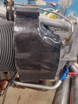
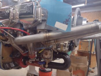
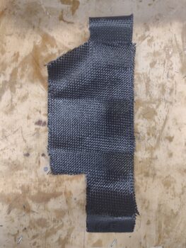
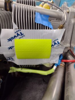
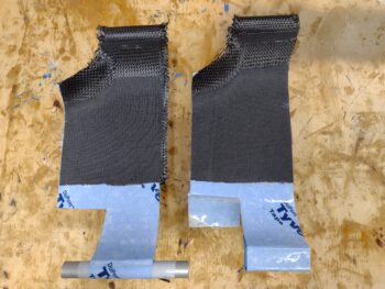
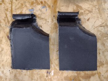
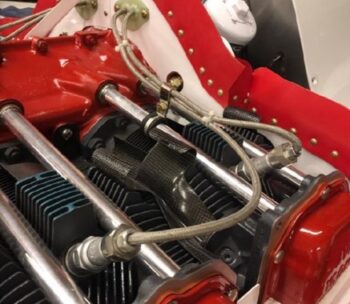
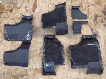
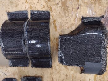
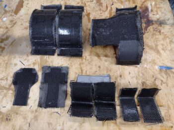
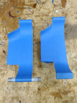
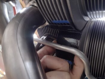
I started out today by focusing on trimming up the remaining engine inner baffles that I had not gotten to yet, which were primarily the top outboard inter-cylinder baffles.  Knowing that Steve Beert is The Godfather of CF inner baffles I sent him a quick message asking him a few questions specifically regarding these inter-cylinder baffles… in fact, I sent him this pic below to clarify exactly which ones we were discussing.  We had quite an exchange over text on installing the baffles.

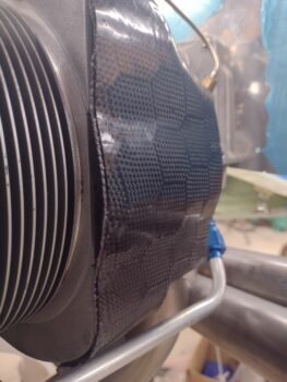
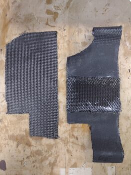
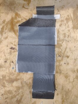
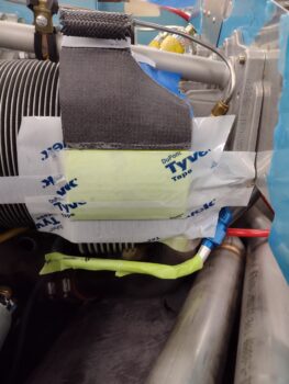
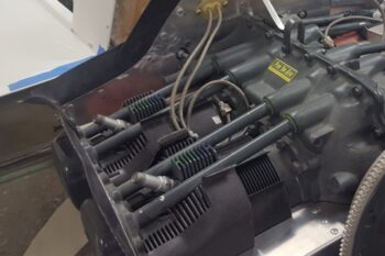
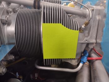
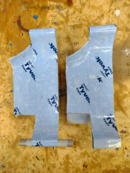
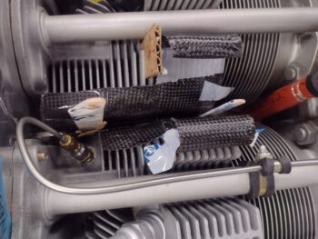
Then a bit later Steve called me with yet even more information, tips and builder tricks on these inner baffles.  We spoke for a good 45 minutes, where he also went over some of the background of the design (Terry Crouch having done the airflow math and primary design with a lot of input by Gary Hertzler) of this style of inner cylinder CF baffles.  I sent this pic below as well of the bottom-side outboard inter-cylinder baffle with a question to clarify some info Steve have presented to me.

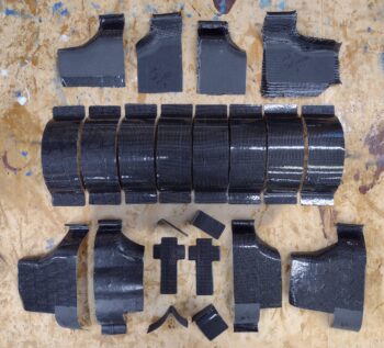
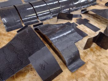
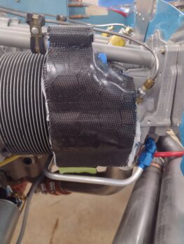
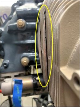
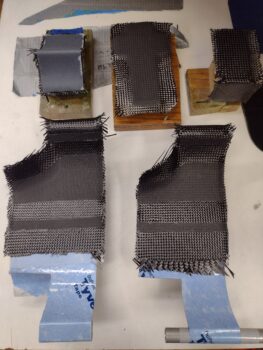
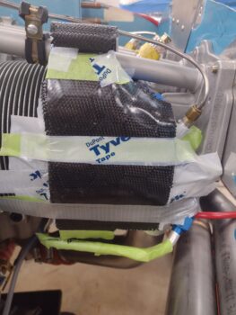
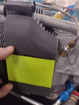
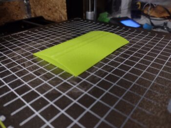
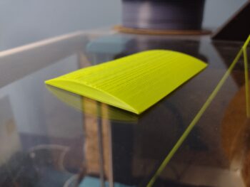
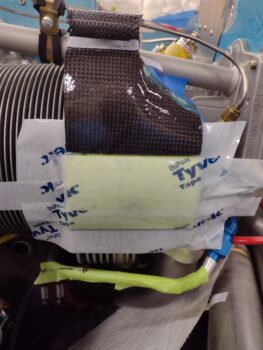
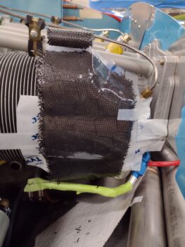
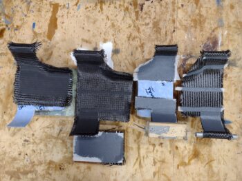
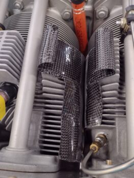
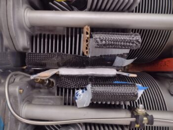
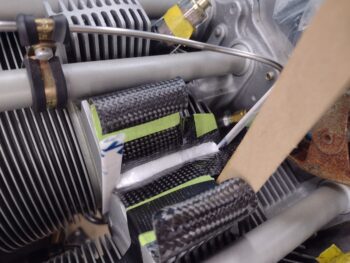
After talking to Steve, with now a bunch of informational arrows in my quiver, it was time to get to work.  I finished trimming and cleaning up the top outboard inter-cylinder baffles, or the baffles that Steve nicknamed: “The Starship Enterprise” and set them into place between the cylinders each side.  Note the taped popsicle sticks on each end to keep the separate baffle segments both in the proper left-right position on their respective cylinders, and also pressed firmly against each cylinder… the intent here is not to create a gap between the baffle segments, but to account for these two previous mentioned factors.

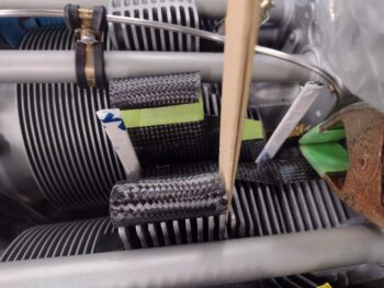
I then followed Steve’s construction sequence by whipping up some micro with the high temp HTR-212 epoxy.   This was a bit tricky both in access to the gap (on a step ladder leaning over the top of the engine) but since I didn’t want to make a mess on the lower internal fins of each cylinder (or the floor, etc.), I had to ensure that the micro wasn’t too runny… thus the medium thickness micro —with emphasis on the thicker— was a bit trickier to stuff down in that narrow gap without it wanting to come back out with whatever implement was being used to get it in there (a variety of thicknesses of stir sticks).  Patience won over though and I finally got a good bead of micro in on each side.

I’ll note that Steve used West’s black dye in his micro in this application, but since I didn’t have any on hand I will simply paint the white micro with hi-temp black spray paint.

Although the weather isn’t as freezing cold this evening as it has been off and on lately, I set up a heat lamp under each side of the engine pointing upwards and covered the cylinder areas with some aluminum foil covered insulation pieces to keep the curing micro from getting too cool overnight.  And with that I called it a night and left these micro’d inter-cylinder baffles to cure overnight.

Chapter 23 – GRT blew it!

To start off with, I’ll note that I don’t like bashing smaller companies who are putting out products for the experimental aircraft world… it’s great to have choices.  But enough is enough.  GRT really gets a bad grade this round (D-) with my order on their compression style EGT probes.

As par usual, there were zero issues with the mechanical process of ordering these EGT probes.  Call them up to ensure they have in stock, order two of them, card info, confirm address… 5 minutes and done.  On my porch a few days later.  EZ-PZ.

GRT’s Achilles heel, and biggest negative, is their product information and documentation.  I had a conversation with Nick Ugolini on this a while back, and he told me as an engineering tech writer he offered to write their manuals for them… for free!  They refused.  I asked another buddy of mine who uses GRT if he would go that route again with any future aircraft… he said no.  Why?  Not because of the quality or the functionality of their products —which is excellent— but again, with no robust documentation you spend way too much time on the phone with them and/or hunting for information that should be right at your fingertips.

Case in point.  I called GRT to get info on their compression style EGT probes because, once again, there is literally ZERO information on these on their website.  I asked about any recommended processes I should know for mounting these into the exhaust pipes? How does the configuration work exactly?  Do they sell the threaded mounting bungs? (no);  Any preferred vendors or sources of supply for the threaded mounting bungs? (no); Now, admittedly this last one I’m fuzzy on, but I swore I confirmed that the required mounting bung threads were 1/8-NPT.  Apparently not.  Neither was that information provided (via product info sheet) nor offered when I was clearly asking every question I could think of regarding the install of these compression style EGT probes.

Well, when my 1/8-NPT threaded stainless steel mounting bungs arrived today from McMaster-Carr, I quickly noted that they were not the correct size.  But what was the correct size?  After 15 minutes of no joy in trying to figure out this odd thread size, I punted and called GRT, leaving my message to have them call me back later as the standard process goes.  And a half hour later got my answer: M8 with 1.0 pitch.  Yes, being in the good ‘ol US of A we tend to use ASI vs metric, but I do use metric hardware enough to know that the standard pitch for an M8 thread is 1.25, not 1.0.  Hmmm?

After a good 30 minutes of searching in vane on the Internet for a vendor that sells a stainless steel M8-1.0 threaded mounting bung, I gave up and finally went to the only source of supply I could think of that would have such an item: Ebay… well, China to be even more exact.  Yep, there they were!  Less than 20 bucks for 3 of them shipped from Shanghai and only a month to get here.  Thanks again GRT!

In other news . . .

Today I finally finished the trimming and shaping of the majority of inner CF baffles. Over the past few days I’ve done a few redo layups since using tape on the forms there were few quality issues I had with some of the baffles. Thus the redoes.

With the glossy surface the lights blanket out some of the CF print, so I grabbed these lower angle shots to show different perspectives on the CF.

And as a reminder, the aft inner baffles are the same print as prop spinner and flow guide.

Overall I’m very happy with how the CF inner baffles turned out, and plan to start mounting them to the engine… after I get the aluminum fin standoffs made up and mounted to the cylinders first.

Chapter 23 – Inner baffles: final layups

I started off today by calling GRT to order 2 of their compression fitting style EGT probes.  Knowing what I know now and the much improved clearance that these will provide I figured the time is right to get them installed.  Plus I confirmed with James that he would be able to weld on the required 1/8-NPT threaded bungs onto the exhaust pipes.  I’ll simply hold the other ones as backups for my other 2 hose-clamp mounted probes.

Out in the shop I started off by pulling all the tape and plastic off the cylinder #2 aft baffle with the fin standoff support bump now integrated into it (pic 1).  I then trimmed the CF around the edges a bit, removed the protective tape off the cylinder, and set the aft baffle back in place for a test fit (pic 2).

Here we have a shot from the side to show the cylinder #2 aft baffle with the fin standoff support bump integrated into the baffle (note: the baffle is about 1/8″ low so it’s not fitted to the cylinder in this pic).

I’ll remind everyone that this fin standoff support bump in the baffle is to allow for these standoff supports as Dave Adams did on his #2 cylinder as well.

I took a couple hours to cut some more CF and lay up a few spares of the inner baffle segments in case I ever run into trouble or just need them in general… before I send the inner baffle molds back.

I’ll also note that the Toyota RTV —that is apparently the cat’s meow for mounting these CF inner baffles— was delivered today.  Now I have no excuse not to get these baffles trimmed up and installed on the engine!

Which I plan on doing over the next few days.

Chapter 23 – Exhaust pipes welded!

I started off this morning by pulling the now cured #2 cylinder baffle —with the fin/baffle standoff support curve integrated into it— off of the aft side of cylinder #2.  I had put a heat lamp on it since the weather (and shop) was much cooler overnight.  I assessed the baffle a bit —all looked pretty good— and then set it aside to remove the bottom cowling to allow removal of the left outboard/cylinder #3 exhaust pipe.

I commenced to remove the tape securing the halves of the exhaust pipe together at the near-center cut and then cleaned all the tape gunk off with Acetone.

While I was doing all these shop tasks, I had already pre-heated my kitchen oven to 400° F and was baking my previously “super-soldered” brass oil sump standpipe fitting.  My goal was to separate the fitting from the standpipe tube to allow James to braze it with some 1/16″ Silicone Bronze welding rods I picked up to allow TIG welding brass. Well, an interesting thing happened, or didn’t happen… whereas at 400° F previously I was able to remove the soldered pipe from the fitting, now it wasn’t budging. Hmmm?

I threw the standpipe assembly in the truck as well and headed out to James to weld the exhaust pipe, and also have a discussion on the standpipe.  My thoughts, in composite parlance, is that I had essentially post-cured this sucker and that it was now battle-tested to withstand 400° F without any issue… very interesting.

Again, it’s a good hour over to James’ shop and since Jess had a light work day I brought her along.  Unbeknownst to me, Jess’s mom is from the same area (“out in the sticks”) where James’ shop is… so after James had welded up the pipe an elderly friend stopped by and a whole conversation of who-knows-who ensued.   Combine that with a late lunch/early supper in Jacksonville and we didn’t get back to my house until very late afternoon.

And here we have the final piece of the puzzle (better be!) with the left outboard/ cylinder #3 exhaust pipe welded back together.  Now I can start on the final configuration of the tips in earnest.

BTW, James confirmed my theory on the soldered brass standpipe.  He also quipped that if I’m seeing over 300° in my oil sump that I’ve got lots worse issues than the standpipe… good point James, good point! <ha>

Back in the shop I got to work on the cylinder #2 aft baffle with it’s new integrated standoff bump.  I cut a ply of CF to fill just where the standoff support form was located and another full ply of CF to hold it all together on the interior of the baffle.  I then mixed up some HTR-212 epoxy and laid in the small filler ply of CF (pic 1) before laying up the interior ply of CF (pic 2).

I then of course peel plied the layup.

I let the baffle cure for nearly 2 hours to tack up before then setting it back onto the aft side of cylinder #2 (which I taped up completely to protect from any errant epoxy).  I taped the baffle securely in place to the cylinder since this will be the final cure and set a heat lamp on it while it cured overnight (much colder tonight than last night).  I’ll also note that the cylinder #2 fin/baffle standoff support mold was still in place on the cylinder to ensure the final shape is as optimized as possible.

And with that, I called it a night!


Chapter 23 – Inner baffles… end is near!

I actually started off today out in the shop to do some more inner baffle layups (see below), but apparently in my haste to get stuff done didn’t grab any pics of the initial layups.

After I got the layups situated (thankfully the weather went into mild mode over the last couple of days) I modified my cylinder #2 fin/baffle standoff support template to a simple rectangular shape based off my test fit yesterday.  As a reminder, here’s what that looked like:

After I got the major dimensions dialed in on my CAD model, I then created a vertical arch that is 1/4″ high in the center for my fin/baffle standoff support mold.  I kicked off the 3D print of the mold and then went out to the shop to prep the cylinder for the mold.

Here’s the cylinder #2 fin/baffle standoff support mold taped to the front of the cylinder.  After I got the mold placed, I then spent a good half hour trimming and sanding the top and bottom baffle segments to get their mating edges even and just kissing the top and bottom edge of the mold.

I then taped up the mold, which then allowed me to secure the cylinder #2 top aft baffle segment in place (pic 1).  I mixed up some HTR-212 epoxy to apply peel ply to the mold only, and then wetted out the surface of the top aft baffle segment (pic 2).

I did some dry runs on the the bottom aft baffle segment before adding tape to the inside of it.  I then laid up the single ply of CF (note: same print as spinner!) onto the free and unattached bottom aft baffle segment before securing it into position with its inside taped surface… I pretty much had to work it this way since the oil return line is in the way and I didn’t want to have to try to layup the CF around and under that oil line.

After I got the ply of CF laid up and trimmed I then laid a piece of plastic over it to provide that glossy, non-bumpy surface like all the other inner baffles have.  I then left it to cure overnight.

After getting the aft baffle on cylinder #2 squared away, I then pulled the peel ply and did some trimming on the narrow top outboard inter-cylinder baffle segments.

Here’s the non-cylinder mating side of those baffle segments… and I’ll remind everyone that these will get merged (separately, one per each side of the engine) with the larger end baffle segments to create the top outboard inter-cylinder baffle segments…

And to be clear, here are a couple shots from a couple different birds on how the top outboard inter-cylinder baffle looks when completed:

I’ll note that tomorrow I’ll be heading out to James’ shop to get the last exhaust pipe welded up, so it will be a slightly lighter build day.

Chapter 23 – Cylinders 2 & 3 end baffles

I had some decent build plans for today but it turned out to virtually be a non-build day in most regards.  Last night I got an email saying that our monthly EAA meeting was this morning at a local restaurant.  I texted the new Canardian in the area, Guy Williams, about the meeting since I wasn’t sure if he was on the email.

I also received a text from my friend asking if I could watch her daughter, aka “my little buddy,” while my friend went to a doctor’s appointment.  No problem there either.

After the EAA meeting, Guy and I went to the airport to check out his Long-EZ.  It’s a beautiful classic built in 1982.  He and his dad, who owned it for many years before Guy took ownership, converted it from an O-235 to an O-320.  Guy moved out here this summer from Tehachapi, CA… home of Marc Zeitlin and Mike Melvill.  Thus Guy clearly had plenty of expert help on hand to assist with engine conversion, etc. on his Long-EZ.  And of course it’s great to have another Canardian at the airport, especially one of the Long-EZ persuasion!

Now, in my mind I figured a doctor’s appointment would take an hour or two at most, and although I only know that it was NOT anything serious, this appointment ended up being over 4 hours… that had me on kid-watching and entertaining duties.  By the time I got home it was well past 4 pm and I was due to have a dinner/evening out with Jess… so my already shortened work day was severely truncated by events that plopped onto my schedule just the night prior.

Out in the shop I pulled all the laid up baffle segments off their respective molds and pulled all but one piece of peel ply (only because it has such clear baffle edge trim markings on it).  I can tell you the added 6-8 hours of cure time with these baffles on the molds was felt significantly as they were MUCH harder to get off each mold!

Here’s the tally, starting CW from the lower left corner:
– “Old” top outboard wide inter-cylinder baffle (to be joined with narrow baffle segment)
– Opposite side of above, just laid up… now just need to layup narrow parts for these
– “Old spinner print CF” end baffle now relegated to duty on front of cylinder #4
– 2 pcs for cylinder #2 aft end narrow baffle that will get middle fin extension area added
– New “spinner print” aft end baffle with much better looking CF for cylinder #1
– New narrow end baffle for front side of cylinder #3

Also, before I headed out to the shop I quickly drew up in CAD and then 3D printed an initial template for the cylinder #2 fin extensions and associated baffle curve over these extensions.  Here’s the result that I temporarily taped up in place.

And an idea of how the top and bottom baffle segments will get melded with the upcoming semi-circular cylinder fin standoffs.

With that, it was time to get inside, clean up and head out for a Saturday evening with Jess.  Tomorrow I definitely intend to get at least the 2 partial narrow baffle segments glassed up for the other half of the top outboard inter-cylinder baffle assemblies that need to be floxed together back-to-back to make up those baffle segments.  I would also like to get some machining done, with the baffle extensions getting made to confirm the configuration for me to then “glass” (CF) up the gap on frontside cylinder #2 baffle.

Moving forward!

Chapter 23 – Inner baffles Round 3

I started off this morning by pulling the two cylinder base inner baffles of their molds, as well as the new cylinder #1 aft end baffle off its mold.  The big reveal I mentioned yesterday is that they’re sporting the same CF print as the spinner and flow guide!  The cool thing is that these will all be fairly visible on the aft side of the engine when you look into the aft cowl opening.

Unfortunately, this CF is a bit thicker weave and I think I was a hair thin on epoxy in a few spots so the spots look just a tad dry in the light (just cylinder #1 baffle).  I have no doubt that it will still work and that it’s mainly cosmetic, but I’ll be relegating this new cylinder #1 aft end baffle to the frontside of cylinder #4, where it’s not as visible.

Along with the cylinder baffles, I laid up the second set of “accessory” pieces that are shown along the bottom of the pic (from L to R): the top inboard inter-cylinder baffle plate, the bottom outboard inter-cylinder baffle, and the angle bracket that screws into place between the cylinders at the top to secure the top inboard inter-cylinder baffle plate.  All told, this completes the cylinder base baffles and the “accessory” baffle parts.

For the larger cylinder end baffles that still left a redo on the cylinder #1 aft end baffle to get better epoxy coverage, and another partial end baffle for the other side top outboard inter-cylinder baffle.  Again, these partial end baffles will be merged (separately) with a pair of also partial narrow end baffles (below) that at full length are for the front side of cylinder #3 and the aft side of cylinder #2.

Speaking of which, I prepped the narrow end baffles by taping them up first with blue tape (pic 1) and then using the Tyvek tape on top of that as a mold release (pic 2).

I’ll note that on the cylinder #2 baffle I added a lip [a curl would be much harder to fit into place with oil line present] and a curl on the cylinder #3 baffle [also an oil line present, but at the forward side of the cylinder the bottom length of the baffle will be shortened with the curl positioned much higher up/closer to cylinder].

I then did the inner baffles Round 3 layups, which from left to right is as follows:
another partial end baffle for the other side top outboard inter-cylinder baffle;
the redo on the cylinder #1 aft end baffle;
top & bottom sections of aft cylinder #2 baffle (middle to be laid-up over fin extensions);
narrow front side end baffle for cylinder #3;
extra top inboard inter-cylinder plate (if/when fuel spider goes underside…bottom of pic)

My last point of note for the day on the build is that I spoke with my welder, James, who has been quite busy as of late, to set up an appointment on Monday to get the last exhaust pipe (cylinder #3) welded up.  From there I can do my end trimmings and final tweaks to get this exhaust pipe saga closed out.

Tomorrow I plan on doing another round (hopefully final) for the engine inner baffle layups.  This should get me close to having the full set I need to start trimming these inner baffles up and installing them all.